7mm 7mm Mick's Workbench - LNER A2/3 60514 Chamossaire

7mmMick

Western Thunderer
That is coming along a treat, some nice touches and very clean work. The lamp irons look very good castings are they Laurie Griffin ones?

Have I understood correctly, are you intending the angle to be curved around the boiler? To be honest I'd be wary of doing this with angle, due to it's inherent structural design angle is never very happy being curved and I've often found it's often more trouble than it's worth as it distorts too much. I usually would cut a curved strip for the cab and separate strip around the boiler, unless you have a cunning plan.

Hi Adrian,

Thank you for your kind comments, the lamp irons are Laurie Griffin. He does a set of NER lamp irons which are lovely and I always use. I know exactly what you mean with the angle. I have used it for this purpose before and as you say it put up a real fight and when bent it just tried to keep its form. However because it was annealed it did accept some gentle persuasion and looked ok. I may well try your method this time though, the bottom section wrapped around the boiler is the easy part but what about the upstand of the angle? If annealed will it form round? I do have some suitable brass strip for this,

ATB Mick
 

7mmMick

Western Thunderer
Adrian, JB,

Very useful cheers. I'll give the lathe option a go. I need to get across to my mates and use his lathe to turn up the smoke box door rings so I'll have a crack at this at the same time. I'll post the results when I can,

thanks again Mick
 

farnetti

Western Thunderer
One good thing about these photos is that they show up and glaring errors

Totally agree and have gone back several time to correct work not seen with Mk1 eyeball.

The 517 build looks great, more so because you had to start from a dodgy beginning.
 

7mmMick

Western Thunderer
As per it's been far too long since my last update due to me having zero time at the bench in the last few months and unfortunately there's probably little chance of much more before September I would have thought. So the J72 moves forward. To pick up on the last posts I tried the method advised by Adrian but for one reason or another it didn't work out, so I reverted back to using 1mm angle, not good engineering I know but never the less it's achieved what I wanted. You can make it out here, although it's out of focus it looks right and does it's job of holding the boiler in position well.DSCF3222.jpg

I then decided to move onto the frames and get them done as there's not a great deal more to do on the body. First job was to thin down those coupling rods as the more I looked at them I didn't like them. Following Mr Dunhill's lead I put a decent amount of time into these thinning them down and rubbing them up with wet and dry of different grades.
So onto propulsion........ there's not a great deal of room inside that little fire box so I sought the advice of Steph Dale. A few Pm's were exchanged and within about a week a super duper Steph Dale gear box with motor fitted arrived, it was duly installed, with a split axle and ran spot on. Putting the coupling rods back on saw me have a real headache though, as there was a nasty tight spot that took some real shifting, totally down to me but in the end it's sorted and lessons learnt for the next build. Nearly binned the thing more than once!!
DSCF3233.jpg
DSCF3226.jpg
With the chassis now running smoothly I turned my attention to the crank axle. This is held with loctite 638. The first time round I didn't make the cuts in the axle where the cranks would sit, more through forgetting than anything (only my second crank axle and the first was put together by Col Dowling). So when I got to it with the fret saw it fell to bits :headbang::headbang:Anyway when the cuts were put in as Col did last time all went well;
DSCF3223.jpg
Finally the motion has all been cleaned up and the cylinder front and rear put together, not quite as refined as I would like but the only way is up as they say and overall I'm happy. I have to put the cylinder bottom cover on yet but it's coming together at least;
DSCF3221.jpg
The cylinder front covers are part of the LG motion kit but the valve cover is brass plate and scale hardware scratched together, just the inspection cover to fit here, and the lamp irons to straighten :thumbs:
DSCF3229.jpg
DSCF3231.jpg
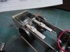
A side on view shows where the firebox bottom and ash pan will cover Steph's lovely gearbox. I'm looking forward to getting the inside motion working as in my mind that will see the last major component part complete and then to final detailing, my favourite bit :thumbs:

ATB Mick
 

Attachments

  • DSCF3227.jpg
    DSCF3227.jpg
    82.3 KB · Views: 15
  • DSCF3224.jpg
    DSCF3224.jpg
    82.7 KB · Views: 15

Scale7JB

Western Thunderer
Really lovely Mick!

Shame you're not more local, as we've got JOEM turning up at the EOR next week..

JB.
 

7mmMick

Western Thunderer
Thanks fellas :thumbs:

That is a shame JB, could have squeezed me on the foot plate:)). Say hello to FiftyFourA of this parish for me, I think he's coming down with her as support crew?

Not yet Len, soon though I hope. I managed to get these shots of Joem at a recent Shildon visit. The spark arrestor would not be fitted to mine in 1950, well it would have one, just not this type I don't think and the brake ejector is not fitted to mine as it's steam braked only.So really I'll knock up a blast pipe, main steam pipe and blower valve and that'll do me I think?
IMG_3198.jpg
IMG_3197.jpg

Cheers Mick
 

Dog Star

Western Thunderer
Mick,

Please walk us (me) around the fittings on show. I can recognise the main steam pipe to the cylinders... and think that the big bore pipe in front of the main steam pipe is the brake ejector exhaust... what is the purpose of (each of) the three smaller bore pipes?

thanks, Graham
 

Scale7JB

Western Thunderer
The two to the right are for the blower, I believe the valve is probably on the outside of the smoke box, and the one to the left would be the water drain off of the ejector exhaust pipe?

JB.
 

7mmMick

Western Thunderer
You're right JB the two to the right are the blower valve. The control rod runs through the firemans side handrail and on nearly all NER types enters through the smokebox at the end of the handrail. I'm not entirely sure how the blower works but I know when it's opened it creates draw on the fire and prevents any blow backs into the cab through the fire hole door. The other pipe is part of the brake ejector gubbins I assume??

ATB Mick
 
Top