You are using an out of date browser. It may not display this or other websites correctly.
You should upgrade or use an alternative browser.
You should upgrade or use an alternative browser.
Easybuild DMU power bogie for S7
- Thread starter Dog Star
- Start date
Scale7JB
Western Thunderer


Steph Dale
Western Thunderer
Mike, help! I think it was just below; I know Mike was interested to model an open interior in his Sandite unit, which is why he didn't use another solution.Thank you Steph,
The side-elevation suggest that the bogie mount is going to be above floor level... or have I mis-read your solution?
Two powers and one trailer I think I'd be going for two power bogies...Your suggested performance... one powered motor bogie for one power car and one trailer car - or two power cars plus one trailer car?
I am not sure why I would want something that was different to a solution that is acceptable to Heyside. Do you wish to take this RTR discussion off-line?
Happy to discuss options/solutions here or off line, as you wish as the FS don't seem to mind!
Indeed! Ssssshhhhh...
Very early BR though..
JB.
Aah - the 'Wonder Loco' as the drivers of Brighton shed called it. As in 'I wonder if the b****y thing will start this morning'...?
Steph
Seahaven
Member
I have also worked on an Easy build DMU in S7.
My solution was to use Slaters wagon wheels with holes filled.
Out axle centrally rocking to provide some compensation.
Drive to inner axle of two bogies, with the motor hidden behind castings.
Works, requires weight over driven axle to reduce slipping.
From the side, little evidence of the drive system.
Attachments
Steph Dale
Western Thunderer
I have also worked on an Easy build DMU in S7.
My solution was to use Slaters wagon wheels with holes filled.
Out axle centrally rocking to provide some compensation.
Drive to inner axle of two bogies, with the motor hidden behind castings.
Works, requires weight over driven axle to reduce slipping.
From the side, little evidence of the drive system.
Great stuff - I'm just wondering whether you can advise what universal joints you used and what radius your DMU will go round?
I've got the gearboxes, drivelines and motor brackets etched up already, it's just finding the u/js that's holding me back from doing it the way you have!
Cheers,
Steph
SimonT
Western Thunderer
I have just picked up on this and discovered that a year ago I promised a shot of the bogie. Funny thing is that just like last year I have a layout packed to drive up to the Leeds show; no truck needed this year and set up/packed in ten minutes") .
.
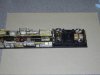
The underside of a power bogie.

All very simple. If I remember correctly, Shawn kindly produced his wheels to S7 standards for me. I have a vague memory of sending the gear and Delrin cogs down to Shawn. I think that he is not keen to repeat the S7 experience again. The axles run in the supplied bearings set into the metal stretcher; the plastic sides are purely cosmetic on the power bogies. This configuration does have the disadvantage of the motor sticking up into the body. At the time I was more interested in getting enough stock built to operate the layout with the oncoming express headlight of shows.
My DMUs get by with 2 car - one power bogie, 3 car - two power bogies. They go round the 75inch minimum radius with no problem. The power bogies only have a small amount of slop through the pivot bolt hole to help with road holding but don't seem to be disadvantaged by this as I only remember them falling off through miss set turnouts.
From the discussion above, I suspect that this won't be of much help.
SimonT
.The underside of a power bogie.
All very simple. If I remember correctly, Shawn kindly produced his wheels to S7 standards for me. I have a vague memory of sending the gear and Delrin cogs down to Shawn. I think that he is not keen to repeat the S7 experience again. The axles run in the supplied bearings set into the metal stretcher; the plastic sides are purely cosmetic on the power bogies. This configuration does have the disadvantage of the motor sticking up into the body. At the time I was more interested in getting enough stock built to operate the layout with the oncoming express headlight of shows.
My DMUs get by with 2 car - one power bogie, 3 car - two power bogies. They go round the 75inch minimum radius with no problem. The power bogies only have a small amount of slop through the pivot bolt hole to help with road holding but don't seem to be disadvantaged by this as I only remember them falling off through miss set turnouts.
From the discussion above, I suspect that this won't be of much help.
SimonT

Ressaldar
Western Thunderer
Hi Graham,
herewith as promised, underside photos of my Easybuild 121 showing
a - underside of Steph's little box of tricks

and
b - what I have done to the floor pan by way of removing the stiffening ribs from the centre. The cut through at the front (left hand side) are vertical and those at the trailing end are at an angle to allow for the angled part of the gearbox to swing without interference. The rectangular hole is for the bogie wiring to pass through, I have fitted a two pin micro plug and socket for ease of fitting the decoder at a later stage.

I have not had to recess any of the underfloor area and as stated on my build thread, I have deliberately left the 'knock-out' panel in to retain the floor integrity. The squares are 8mm x 8mm.
I hope that this is of use to you.
regards
Mike
herewith as promised, underside photos of my Easybuild 121 showing
a - underside of Steph's little box of tricks
and
b - what I have done to the floor pan by way of removing the stiffening ribs from the centre. The cut through at the front (left hand side) are vertical and those at the trailing end are at an angle to allow for the angled part of the gearbox to swing without interference. The rectangular hole is for the bogie wiring to pass through, I have fitted a two pin micro plug and socket for ease of fitting the decoder at a later stage.
I have not had to recess any of the underfloor area and as stated on my build thread, I have deliberately left the 'knock-out' panel in to retain the floor integrity. The squares are 8mm x 8mm.
I hope that this is of use to you.
regards
Mike
Steph Dale
Western Thunderer
Dave,I did wonder, knowing what a fan of split axles Steph is! Thanks Mike.
That's an interesting point, but the power bogie is fully ball-raced and has a metal frame. Splitting the frame electrically probably isn't all that straightforward and even if I had worked out a way to do it the bearings wouldn't have been the best way to pass the current - so I would have ended up using wipers anyway!
Steph
Steph Dale
Western Thunderer
Steph
The universal joints come from Branchlines.
Gearbox is homemade using Romford 20:1 gears.
The model has worked round a 6ft radius curve with no problem if driven carefully away from the start.
Hope this helps
It certainly does - looks like I need to get a version made up and see how I get on with it!
Very many thanks,
Steph