Len Cattley
Western Thunderer
Heather you put much better than me ")
Len
Len
Didn't know you two were golfersHeather you put much better than me
Len
") this should explain all and allay your fears
this should explain all and allay your fears 

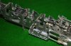
 This shows that I may have put part number 362 on the wrong way up. I am guessing this because the three holes to take the damper levers have ended up on the wrong side. However putting it the other way up would mean that the fold for the panel at the front with three round gaps in it would be on the wrong side to bend it downwards - ie the bend would be away from the etched line. This is why I used it the way up which you can see in my pictures. Also the half-etched areas at the front on the curved plates I thought must be on the outside, because otherwise they would be completely hidden!


Hello DavidPlease could I have some more help and advice?
I may have made a mistake, which has exposed a difficulty/problem with the etches (not related to S7), and I also need to some advice/help about cab construction. I will attach some pictures.
The first part is probably only going to make sense to someone who has made or is making this particular kit. The first picture shows the overall basic construction from the front:
View attachment 38062
On the underneath of the cab is part no 362, which is curved upward to make the curved plates leading up to the footplate. View attachment 38061 This shows that I may have put part number 362 on the wrong way up. I am guessing this because the three holes to take the damper levers have ended up on the wrong side. However putting it the other way up would mean that the fold for the panel at the front with three round gaps in it would be on the wrong side to bend it downwards - ie the bend would be away from the etched line. This is why I used it the way up which you can see in my pictures. Also the half-etched areas at the front on the curved plates I thought must be on the outside, because otherwise they would be completely hidden!
So, if my analysis is correct, either the three holes for the damper levers are on the wrong side, or the etched line to fold the front plate is on the wrong side.
Now, advice, please.
If you look at picture No.s 3 and 4, you can see that despite my care I have ended up with a gap between the cab-side etches and the curved part of part number 362.
View attachment 38060
On the right side this doesn't matter, because if I push the curved part upwards, it neatly fits behind etch number 367 (this is the front of the cab, immediately behind the whitemetal firebox I think). This allows the shiny (unetched) strip at the side of the curved part on 362 to line up with the shiny strip along the lower edge of part number 367. Fine, it looks made to do just that. There will then be no gap along the bottom of the cab-side etch. The trouble is that on the left side, the curved part on 362 just abuts the thicker edge of part number 367 rather than going behind it, and leaves the curved part on 362 with a gap between that and the cab-side etch. This could be cured by removing a mm from the upper edge of part 362, but I'm reluctant to do that without knowing that it really needs to be done. Also with the assembly done so far, it will be awkward to do. You see I have become used to the idea that all the parts in this MOK kit fit perfectly!
View attachment 38059
So if anyone knows the answer as to what I should do, I would be grateful for help, once again.


Mark J was absolutely right.
By e-mail I found out from MOK (Dave Sharp) that I had definitely put the base of the cab on upside down. As Dave said, the instructions are "carp" (anagram) at this point, and actually the drawing is downright misleading. This has all sorts of minor but annoying effects. One was the fact that the formers inside the base of the cab had been made to accommodate the etched plates which were meant to go inside the curved sections (making them invisible - they are there only to make curving these areas easier). So the formers made the curved plates have a larger diameter of curve. This might only be a larger diameter by half the thickness of the N/S sheet (about 0.3mm therefore!) but this led to the gap at the outer end, exactly where I had found one. See the pictures in my last post.
After much internal debate, I decided that I would never be happy if I did not do the job properly, so I pulled all the cab base apart using my 75 Watt soldering iron. Once back to the component parts I tried to clean all the solder off the nickel-silver, then I flattened the bottom plate completely (apart from the front plate) first with my fingers, then with a tap hammer on a piece of flat granite. The front plate (with three holes) is now bent upwards as it should be.
I then reformed the curves, fitted the formers back (now easier because the former correctly fitted onto the curved sections.
David


I assume that a piece of wire is needed to carry current from the axle through the hornblock bearing to the motor (right of fig.1), soldered in place.