Stanier 8F in S7

mickoo

Western Thunderer
What Steph says is right but you can also deepen the axle countersink and that's what I do, but you have to do it a little more than the wheel.

Pictures...we like pictures:thumbs:

Standard Slaters wheel
Image2.jpg
Black is the wheel, red the axle and green the retaining screw. The screw grips on the chamfered edge and should not bottom out on the axle end.

Thinned wheel
Image3.jpg

The axle protrudes more and the retaining screw bottoms out on the axle end leaving a gap twixt wheel and screw, normal procedure here is to skim the end of the axle at the blue line to move the screw down and grip the wheel.

However I prefer to countersink the axle like thus.
Image4.jpg

When you do it this way you must make sure the axle counter sink is lower than the retaining screw or as Steph says the screw will bottom out on the axle and not grip the wheel. I do it this way for several reasons, primarily it's bloody easier, quicker and quieter, just wind the counter sink in a couple of mm and your done, as it goes in it automatically reduces the height of the square boss on the axle. In addition you don't muller your tool tip turning a square end, none of this dang dang dang as you wind the tool in, and thus quieter.

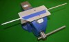
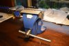
Another reason for doing it this way, you don't need a lathe, you can mount the axle vertically in a tool vice and drill the counter sink, you could of course also just put the axle in a vice and file the end off, it doesn't need to be square as the faces that do are not the axle end where the screw goes in.

Finally as can be seen in the photos below, you retain more of the square axle end in the corners to hold the wheel, it's not much but every little helps.
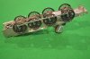
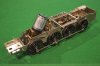
Assembled wheel set
Image1.jpg

Axle end
Image2a.jpg

A trimmed axle end would only be as high as the lowest part of the semi circles on each face.

Both methods are right, it's just which ever you prefer but in both the critical point is that the retaining screw must grip the wheel countersink and must not bottom out on the axle end, how you achieve that is your choice.
 
Last edited:

mickoo

Western Thunderer
Tender wheels, the 8F books do not have much info on the tenders, much of that is in the Black five books but even then they focus on the bodies and not the frames and running gear, there are some cross sections in the Royal Scot and Princess Coronation classes, both use pretty much the same running gear with most of the changes being above the footplate for capacities etc. In both those classes the tender wheel boss protrudes by approximately 1", I say approximately as no dimension is give, I've just measured it with a rule on the drawing.

Regarding driving wheels, your right I think even the S7 one might be a bit thick, certainly the finescale ones are, one of the easiest (if you have a lathe) tricks to gain more clearance with finescale ones is to skim 10 thou off the back, this will still give the correct back to back (the axle remains the same length) but moves the coupling rod face inward by 0.25mm each side, in addition you'll now have a slightly narrower rim and thus a corresponding increased gap between rim and rail head, this will give the loco more side play when going through curves.
 

DavidinAus

Western Thunderer
Firstly, progress on the wheels. Then, progress on the tender.

The wheels being too thick at the centre is crucial I think. I was a bit doubtful about my ability to thin them down well and evenly using Steph's emery paper method, but fortunately Richard Davidson in Melbourne is happy to thin them down for me, so they have gone there for treatment on his lathe. He says that compared to a Finescale wheel they are 0.6mm thinner at the rim, but only 0.2mm thinner at the boss. Once the basses are 0.4mm thinner each side, the wheels should easily fit within the tender frame. What is even better, of course, is that the driving wheels being thinner at the centre should make it easier to fit everything in behind the cylinder slidebars and crosshead.

While the wheels are away, I started on some of the bodywork for the tender. For someone like me, this threw up some significant difficulties due to my lack of expertise: how to bend the top edge of the tender sides? I have bent sheet metal before, to make the Belpaire firebox of my industrial Garratt, but this was brass, and not a particularly wide sheet of metal, either. The nickel-silver sheet for the tender side requires an even bend along a length of about 11cm. Dave Sharp from MOK has instruction about how to do it, but they are sketchy. The bend covers a height of about 3.5mm in the side, so I worked out that as the bend was through about 45 degrees, a bend of about 8mm diameter would be about right [8x3.5=28mm, divided by Pi = approx. 8mm diameter].
The instructions show how to draw lines on drafting tape inside the bend, to position it accurately. This is good, but how to make the bend? My first try was to place a slightly smaller diameter drill to bend around, and clamp the tender side in my big vice.

Small Bending the tender sides 02.jpg

However I simply couldn't bend the nickel silver!
In any case, the drill wasn't really long enough, and the ends might not bend properly. I was talking/e-mailing Richard at the time, and he suggested I buy a longer rod, of slightly smaller diameter than the bend I wanted to make, and then either roll the sheet over the rod using a rigid metal plate to transmit even pressure, or clamp the top edge of the tender side in the vice and bend the body over the bar. I suppose it was a little foolish of me to try to do it the other way around, but somehow it seemed right to bend the bit that is supposed to be bent, rather than bending the body down whilst holding the part which is supposed to be bent, upright in the vice!
I started to try to bend the sheet over a piece of 1/4 inch (6.3mm) aluminium rod which I found, on our granite kitchen benchtop (the household manager was out), but it was very difficult to bend, and also I thought that this technique might not produce a discrete bend in the flat sheet of the tender side (if you see what I mean), but rather make it a nice continuous curve in the metal sheet. It was impossible to hold the rod still relative to the sheet metal whilst trying to make the bend.
So, back to the vice. The trouble now was to hold everything at once, to allow the rod and the tender side to be exactly positioned. So I used masking tape to hold the rod against the aluminium angle used to make smooth jaws in my big bench vice, like this:

Small Bending the tender sides 03.jpg

Then I put the tender sides into the vice and could adjust the position so that the start of the curve was held in between the rod and the vice, the other end of the curve being above this (in the picture one can just make out the second line):

Small Bending the tender sides 04.jpg

This finally allowed me enough leverage, using a thick rigid steel rule, to make the bend in the tender sides.

Small Bending the tender sides 06.jpg

It also allowed me, using the same technique, to form the vertical curves at the front of the tender sides ( a bit out-of-focus in the picture, sorry):

Small Bending the tender sides 05.jpg

HAPPINESS !

David
 

Attachments

  • Small Bending the tender sides 06.jpg
    Small Bending the tender sides 06.jpg
    116.7 KB · Views: 26
  • Small Bending the tender sides 05.jpg
    Small Bending the tender sides 05.jpg
    105.1 KB · Views: 25
  • Small Bending the tender sides 03.jpg
    Small Bending the tender sides 03.jpg
    131.8 KB · Views: 26
  • Small Bending the tender sides 04.jpg
    Small Bending the tender sides 04.jpg
    214.2 KB · Views: 26
  • Small Bending the tender sides 01.jpg
    Small Bending the tender sides 01.jpg
    249.1 KB · Views: 27
Last edited:

Dikitriki

Flying Squad
I remember this as being a tricky procedure, but you seem to have very even straight bends.

You still have a difficulty ahead as the outer skins need to be bent in exactly the same places. I was doing this while demonstrating at a show, so it was all or nothing in front of an audience:)

Richard
 

markjj

Western Thunderer
The outer sides are a half etched overlay and much easier to bend David.. You can manipulate them over the inner former if you are carefull fairly easily make sure you hold them firmly in place though so the don't move. You effectively get a practice set in the kit as it has both raised riveted and flush riveted/welded ones so use the one you don't want to give it a try first.

Mark J
 

Dikitriki

Flying Squad
Oh dear, Richard, I hadn't even thought of that, yet!
How did you do it?

D
Hi David,

As Mark said, they are half-etched, and present less of a problem. I used finger pressure only round a rod, using the existing sides as a datum. I did the top curve first, checking very regularly against the inner sides, and then did the front curve which was a little more difficult as there is less to grasp. Knowing me, I used smooth jawed pliers and did it bit by bit, a little at a time.

Richard
 

Len Cattley

Western Thunderer
Hi David you could read Grasshopper John in Rmweb on post 55 as he is doing a Black 5, he shows you how to bend the tender sides using a flat jig.

Len
 

DavidinAus

Western Thunderer
An update on progress with the locomotive, in case anyone remains interested.

It must be said that the instructions are a little terse at times, such as this: "Obtain a running chassis" !
After a struggle, this is where I am now at:Small Obtain a running chassis 01.jpg

However it will take a little while to describe how I reached this point!

I had bought the special ScaleSeven wheels, but as discussed above, it seems that the wheels rims/tyres had been made to S7 standards, but the central boss part of the wheels was far too thick. I was lucky once again to be able to enlist Richard Davidson's help, and he used his lathe to thin down the wheel centres by about 0.5mm each. (the tender wheels, by the way, don't need as much taking off). This extra space on each side would be crucial to allow the wheels and coupling rods to turn behind the slidebars and crossheads without catching. Even with the wheels thinned down, it is a very tight fit. It was simply not going to be possible to fit the manufacturer's crankpins, washers and nuts.

Here is a drawing with the dimensions of the special steel crankpins which Richard has made for me.Wheel Bolt.jpg

I decided that on the first axle the special crankpin could be used without a washer inside, as the coupling rod was slightly thicker around the crankpin, giving clearance over the wheel centre. For the second axle, though, a washer would be needed between the special crankpin and the wheel boss, as the articulation in the coupling rod would foul the wheel centre otherwise. For the third and fourth axles the Slater's crankpins could be used.

Shown here are the different crankpins in place.Small Annotated Obtain a running chassis 02.jpg

When I first put the axles in the frames, bolted the retaining plates to keep them there, attached the coupling rods loosely and turned the chassis over: JOY - the chassis could be pushed forward and the wheels all rotated with minimal binding. Too easy, as they say here in Aus.

"Too easy" in fact .... Once I tightened down the crankpins the binding started. I am not sure what the correct way to sort this out is, but Richard had once shown me how to push the frames along, and when the wheels stopped rotating, move each segment of coupling rod sideways with a pair of forceps to see if it moves: even a little movement shows that this is not the part which has stuck. When a crankpin with no movement is found, the hole in the coupling rod probably needs to be enlarged (with a small tapered reamer). I slowly opened out the holes in the coupling rods where the binding was occurring. At least with the articulated coupling rods this is made easier. However it also became obvious that on one wheel the countersunk central bolt holding the centre of the wheel to the axle stood out too far and was scraping against the coupling rod - the bolt had to be filed back just a little.

This all seemed to take ages, and the special crankpins were difficult to take out each time - I had to buy a "pin chuck" (and not a very good one, either, from the local hardware store) to hold the circular heads of the crankpins. However in the end I did "obtain a running chassis", although one without the connecting rods, etc in place. I couldn't then resist a trial fitting of my Portescap motor and ABC gearbox, to see it all turn for the first time!

Using the Slaters crankpins and their "top hat" bushes made the coupling rods stand out an unrealistic distance from the wheels, so next action was to thin down the flange of the top hat bushes (almost removing the "rim" of the "top hat"!), and shorten them so that they are only slightly longer than the thickness of the rods.

After all of this, fitting the cylinder/slidebars/motion bracket assembly revealed that all the work was being rewarded, with a small but definite clearance between the front crankpin and the crosshead on the slidebars.Small Obtain a running chassis 03.jpg

The connecting rods were still not fitted, so next was to attach these to the crossheads. There was nothing in the instructions about how to do this. There is a post coming out of the recess in which the small end of the connecting rod fits, about which the rod will move. I cut this off flat with the crosshead rear (the was no way it could be allowed to protrude!). After some thought I measured the post: 2mm diameter, and made two tiny circles of flattened nickel silver wire (curled around a 1.9mm drill, then flatted between a steel ruler and a granite benchtop with a hammer (lucky the household manager was out again). I could then solder the wire circle around the post to hold the connecting rod in place.

Small Obtain a running chassis 05.jpg

Connecting the connecting rod then allowed me to see the next difficulty - the expansion links have to be made very carefully so as to hang just wide of the connecting rod. I had not done that (it's not easy to see this difficulty before this latest part of the construction), so some reconstruction is going to be needed now.

Could someone suggest to me how I should attach the return crank (I think that's the name) to the crankpin over the connecting rod? Clearly it needs to be fixed firmly, although preferably removable if necessary later. I need to be able to adjust the angle to set it correctly, and there are some nice etches to represent the four-bolt return crank fixing on the prototype. Here are the etches:
fret.jpg

Thanking you in advance for your help.

David
 

Attachments

  • Small Obtain a running chassis 04.jpg
    Small Obtain a running chassis 04.jpg
    201.5 KB · Views: 27

Steph Dale

Western Thunderer
David,
I'm continuing to watch with great interest!
For your return crank and fixing I suggest having a look on this very forum for Dikitriki's approach, it's the same approach I'd take to this knotty little problem.
Steph
 

Heather Kay

Western Thunderer
Steph, Graham, any chance of a link to Mr Lambert's treatise, please?

I did a search, but couldn't find a specific thread.
 

S7BcSR

Western Thunderer
David (and others)

I was a little dismayed to read your comments on the S7 8F wheels and in particular about the bosses being too thick. Whilst no consolation to you at the moment I wonder whether we have had a specification problem or a manufacturing problem or possibly both as, in my opinion, there should not be such a problem. I can't do anything at the moment as our Stores Officer is away on holiday and the ordering of these wheels was made by him and he probably has the specification. However I have passed the comment over to the chairman of the Technical committee (recently set-up and to be announced in the next S7 Newsletter) and asked him to see if there was a problem at some stage in the development and manufacture of these wheels.

Whilst not wishing to say too much in advance of finding out if there was a problem I can only apologize that there has been this problem and that it has affected the building of the 8F, a thread which I have been following intermittently but with increasing interest. I have taken note of some of the other points made by others and will ask the technical committee if we need to have a look again at some of our dimensions. After all nothing is written in stone when modelling only to find the best and easiest way to do something.

As you will note, and I make no apology for this, I am writing in a semi formal vein rather than as an occasional contributor to WT.

Rob Thompson
Secretary, ScaleSeven Group
 

DavidinAus

Western Thunderer
An update: I am still struggling a little with that simple phrase from the instruction - "obtain a running chassis"! Admittedly most of the trouble is related to the minimal clearances available in Scale Seven. To elaborate:
One of the problems I foresaw (and wanted to plan for) was how to fix the return crank. In the end, after reading the contributions above, and discussing with Richard Davidson, I decided on a plan using a threaded top-hat bush (THB), with the rim on the outside, to which I could solder the return crank. I measured the coupling rods and connecting rods so as to be able to minimise the distance that they stick out from the wheel, which is necessary in order to squeeze the connecting rod inwards so as to avoid the expansion link.
Here is the diagram which I drew to help me work out what was possible.

Crankpin and bushes diagram.jpg
I measured the thickness of the coupling and connecting rods, so as to work out how long the thin parts of the THBs had to be, and as you can see it requires a threaded THB on the outside. This in turn meant that I would have to have a new crankpin. I guess it could be done with a long 10BA bolt, with the head cut off, fixed into the wheel with cyano-acrylate adhesive. however the ideal new crankpin would look like this;
Crankpin diagram.jpg
Of course the major problem is the outside THB, which needs to be threaded 10BA. The ones supplied with the wheels are, of course, wide enough to allow 10BA bolts through without obstruction. Fortunately Richard was able and willing to make the new crankpin for me, and the new brass THBs. Here they are:
New crankpins.jpg

Also shown (on the left) are two new pins for the fourth axle, with deeper threads for the crankpin nut, to stop the coupling rod moving in and out too much. In fact this crankpin will be the only one of the four axles to have a Slater's nut, and none if the axles will have a Slater's crankpin! It would be different in Finscale of course, but in S7 the clearances are tight enough to make all these adjustments necessary, I believe.

I'm trying to re-write the instructions for this kit, as a help to David Sharp, and to others who might want to build it to S7. I've been lucky in having Richard to help make the new crankpins, of course. I think it could all be done using THBs soldered onto the threaded shanks of 10mm long 10BA bolts, for the forward two axles. However the need for the threaded THB for the outer end of the main crankpin is a problem. Can anyone tell me where it is possible to obtain THBs with thinner holes (1.2 - 1.4mm)? I have two in my scrapbox, but cannot think where they came from.

Just for comparison, here are the original and new crankpins:
Crankpins old and new.jpg(click to enlarge)
The differences are small, but important, I think. The Slaters ones have flats for gripping them. I hadn't put flats on the new ones at the time I took the picture. I have now.
I made a special tool to grip these flat edges on the discs, from a surgical needle-holder! These are now disposable instruments, believe it or not, so I obtained an unused one and modified it as shown:
Small Tool for crankpins and needle holder.jpg
Small Tool for crankpins.jpg
Specifically just to grip the crankpins !

Slightly distressingly, I realise that I am essentially not much further than I was when I last posted a picture of the chassis/frames. However I can now tell you that with both coupling rods firmly attached the engine runs relatively smoothly, only drawing a maximum of 60mA at the 5 volts needed to make it move, which seems OK to me.
Attaching the connecting rods and pistons, though, causes uneven running: onto the next problem!

David
 

Attachments

  • Small Obtain a running chassis 02.jpg
    Small Obtain a running chassis 02.jpg
    175.7 KB · Views: 26
Last edited:

OzzyO

Western Thunderer
Hello David,

you can get the THB with 1.4mm holes from Slater's (ref No. X720055, £4.94 for ten).

Nice looking crank-pins, but I think that I'd just have used 10BA screws from the back of the wheels. As you can use 8BA washers to fit over the THB and space the rods from the wheel face. A bit like in this drawing.
crank pins.jpg

OzzyO.
 
Top