7mm Steves work bench, project C1 The Ace Ivatt atlantic

topshed34a

Western Thunderer
The cab has now been finished, I added the beading front and back, The beading is flat etch, so I used it on the front of the cab. For the rear it was in 5 sections and the main section over the cab roof was to big so I put it in the bin. Instead I annealed some brass wire and tack soldered with 188 and then flooded the wire with flux and a bit more solder then cleaned up.
Pretty pleased with it reallyC1 cab completed.JPG
 

topshed34a

Western Thunderer
I have to confess, I made a mistake on soldering the footplate to the valences, I should have picked up on it earlier but didn't and how hindsight is such a wonderful thing.
So LEARN FROM MY MISTAKES PLEASE.
foot plate is lower at the front of the cylinders and slightly higher after, ie there is a step, I forgot this, there are even to half etch lines on the footplate so you can put in the step.
So last night I desoldered and made the step, first I bent it the wrong way and when I bent it the right way I could feel that it had fractured but was still hanging on, so carefully laid it on the bench and then ran a fillet of solder along. Now it is all good.

Its things like this that make me know I'm human.
Such a small mistake but so important. Oh well a minor set back in the scheme of things
The mistake I made.JPG
 

topshed34a

Western Thunderer
The cab is looking great Steve, very nicely done..

JB.
Martin, I will take that as a complement, your a details man, so it means a lot to me.
I just want to build it and paint it well. As you can see a minor set back and so many parts I don't know what they are for.
The overall quality of the kit ie the components is good, I probably feel let down by lack of instructions.
I am working on process elimination, build sub assemblies and see the bits left.
It is interesting that my kit has a etched brass fold up back head, not something I would think to make a back head out of , the newer kits now come with a whitemetal casting which I have bought along with some lost wax crossheads.
I think I am just going to take my time, think through things and work things out. It is sometimes easy to get stale and I feel then it is the time to down tools and leave it overnight or perhaps a few days.

My inspiration though is seeing the NRM Bachman model which looks good in OO but how much better in O gauge.
 

Yorkshire Dave

Western Thunderer
I think the downfall of many kits is lack of good documented instructional drawings.

I agree with you on this as there are a large number of kit instructions which are too wordy and leave a lot to be desired. Therefore they become incomprehensible and lead to misunderstandings where a few simple line drawings or photographs would clearly explain. Obviously the author knows what they mean when they write instructions but does anyone else? It's just unfortunate that a lot of, but not all, engineers and designers across industries are not the end users.

Instructions apart, I admire your perseverance, tenacity, approach and achievement thus far with your C1 build and look forward to the completed loco.
 

topshed34a

Western Thunderer
I agree with you on this as there are a large number of kit instructions which are too wordy and leave a lot to be desired. Therefore they become incomprehensible and lead to misunderstandings where a few simple line drawings or photographs would clearly explain. Obviously the author knows what they mean when they write instructions but does anyone else? It's just unfortunate that a lot of, but not all, engineers and designers across industries are not the end users.

Instructions apart, I admire your perseverance, tenacity, approach and achievement thus far with your C1 build and look forward to the completed loco.
Thanks Dave, I am learning a lot and it is amazing what you gain from building other kits. Certain famous loco builders whom I won't mention but you will know of would not touch this kit because they are less than straightforward.
I think there is a real skill in being able to document a build with a few to writing instructions
I think If I were designing a kit I would need to build perhaps 4 or 5 of the kits before I could write down instructions
Things I look for are good drawings with the parts numbered in the order you build them Relevant notes as brief as possible if you need to know how to do something and most importantly being able to identify the parts on the fret.

Having a part list that says lower casing or something obscure doesn't help me find the part if I don't know what it is.
To me the bench mark of how instructions should be written is those by Jim McGeown of Connoisseur .
He told me once he is a simple man and likes to work of good drawings and when I built the J50 I was not dissapointed, simple and an absolute joy to build

But where is the pioneering spirit in me, imagine Peter Denny in his vicarage in austere Britain circa 1950, nothing to buy, just a pair of tin snips, a castrol oil can and big soldering iron that you heat up in a gas rink, Sounds so romantic doesn't it,
Bollocks to romance I just want to build something with ease. LOL
 

topshed34a

Western Thunderer
Well after realizing the cock up I made on the foot plate I took it apart , made the bend and then resoldered it back on.
Now I am simply not sure how the saddle fits also how I fit the whole boiler firebox and smoke box unit.
The instructions are vague, but then what is new about vague instructions in a kit NOTHING
Further correspondence with William on the way.
Seriously I don't think I'm dense I really don't but I just find it hard to know how to do it with out a decent drawing.
Words are not the best way here , as they say one picture is a thousand words.
If I get through this kit Im going to celebrate with a nice bottle of Taylors Clare Valley Shiraz
Front footplate and saddle.JPG Front footplate and saddle.JPG
 

Attachments

  • Ivatt C1 footplate.JPG
    Ivatt C1 footplate.JPG
    275.5 KB · Views: 2

oldravendale

Western Thunderer
Congratulations on having got this far! I couldn't agree more about the instructions. The "K" kit tender was a masterpiece in terms of rubbish instructions - having formed the basic body the best the instructions could do was say that "all the remaining parts can now be fitted in any order". Not true, of course, and as there is no list of parts I didn't know which were for the tender and which for the loco!

I'm still working on starting the chassis for the loco. Photos will follow when there's something to photograph, but three issues so far: there is no hole provided for a lower spacer. Ignoring this will make the chassis incredibly weak so a couple of vertical spacers will be fitted. The fixing holes in these spacers over which a captive 8BA nut is to be fixed are so huge that an 8BA nut almost passes through them. Then, the bearing holes in the coupling rods are about 1.2mm when they are to take bearings of 2.4mm. I'd far rather have a hole which is too small, but that's ridiculous. My loco also has a fold up back head which I'm going to have to use as there's no suitable alternative for a "K" out there.

Overall I'd say your Atlantic may be from approximately the same stable as my "K". More to follow on my "K" build thread in due course.

Brian
 

farnetti

Western Thunderer
I'm with you on a good drawing, Finney the best for me.

The Clare Valley Shiraz may be best for me also, but yet to try it.

Ken
 

topshed34a

Western Thunderer
Congratulations on having got this far! I couldn't agree more about the instructions. The "K" kit tender was a masterpiece in terms of rubbish instructions - having formed the basic body the best the instructions could do was say that "all the remaining parts can now be fitted in any order". Not true, of course, and as there is no list of parts I didn't know which were for the tender and which for the loco!

I'm still working on starting the chassis for the loco. Photos will follow when there's something to photograph, but three issues so far: there is no hole provided for a lower spacer. Ignoring this will make the chassis incredibly weak so a couple of vertical spacers will be fitted. The fixing holes in these spacers over which a captive 8BA nut is to be fixed are so huge that an 8BA nut almost passes through them. Then, the bearing holes in the coupling rods are about 1.2mm when they are to take bearings of 2.4mm. I'd far rather have a hole which is too small, but that's ridiculous. My loco also has a fold up back head which I'm going to have to use as there's no suitable alternative for a "K" out there.

Overall I'd say your Atlantic may be from approximately the same stable as my "K". More to follow on my "K" build thread in due course.

Brian
Brian I think the instructions are really what frustrate me the most.
Your right, now fit the rest of the parts and good luck.
The other word that frustrated me was fettle which means the part is never going to fit unless you hack it and bash it.
Ian rice in his book is pretty scathing about dodgy kits.
The Ace kit isnt bad but I just dont want to guess how to build things.

But here is the problem, I see a loco I want to build and then need to find out not have I the skill as much as is the kit buildable, well thought out .
some kits seem to use the wrong material for the job.
I really think back heads should be cast or now 3d printing would work.
Smoke box saddles are best cast.
I really cant wait to build my finney kits
 

topshed34a

Western Thunderer
Ever had a day when you want to exclaim Whiskey Tango Foxtrot, commonly known at WTF, well today is the day

I need to be Sherlock bleedin Steve to nut out the build for the C1, It would be nice if the parts are all identifiable but they are not, actually exploded diagrams with sequential parts numbers would have been brilliant.
I seem to be building sub assemblies then analyzing what is left over
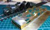
Check out this lot
There are parts on here that I have no idea what they are for. Some I do have like the two floors one is for the tender and one for the loco.
How the whole boiler firebox smokebox joints together I don't know
Then there are the two circulars parts down the bottom, one is horeshoe shaped, again no idea and no diagram.

To quote the words of Alf Garnett, Im goin up the pub

I feel like I need to fly over to see William, I just want to build the blooming thing, that is it.
Im sure the parts are good enough but trying to deduce from scant text and even scantier i there is such a word sketches drawn on the back of a beer mat by someone total excretion faced when he did it.

OK that is it, dummy spit over.
2-004.JPG
 

Scale7JB

Western Thunderer
A and B - cylinder wrappers
C - front boiler former
D - I would say is a mid boiler former
E - could be the smokebox saddle sides
F - Loco drawbar overlay detail
G- Looks like a rear cartazzi frame overlay?

JB.
 

topshed34a

Western Thunderer
Hello All, well the C1 continues. I have got the boiler ready with handrail stanchions soldered from inside.
I have got a lead ballast of 531 g to epoxy in the boiler and am now reading to solder the firebox to boiler.
I will add splashers then saddle then solder boiler and firebox to footplate. I will then be able to cut away the body from the jigC1 boiler construction and lead ballast-005.JPG
 

topshed34a

Western Thunderer
Well next stage is to solder the lot up, So I have added the lead ballast with some epoxy and soldered in the horsehoe former you can just see inside the rear of the boiler, I have also added the firebox front. Now I need to solder up the firebox to the boiler,
As you can see from my photo I have a semicircular overlap that goes over over the boiler , roughly from the hand rail positions each side.
Not to certain how to disguise this, yes it will have a boiler band over it but I think the overlap is going to show.
Don't know if I should file back the over lap to the width of the boiler band or not. I think the boiler band will not be brass strips but rather be simple lining done after the painting has been completed.

What do you guys thinkBoiler firebox joint.JPG
 

Overseer

Western Thunderer
Sorry for not responding sooner and I hope you haven't soldered too much together. Looking at several photos online I think the top of the firebox should be aligned with the top of the boiler rather than having a noticeable step at the joint. The prototype cladding would have only been about 1/8" thick so even if one sheet lapped over the other it would barely be visible. I think the step appearance is visible on some of the C1 models, presumably the same kit?
 
Top