7mm Rob's Rolling Stock Workbench

Rob Pulham

Western Thunderer
Robin,

I can see how these two models fit the idea of timber wagons - how do the kits build into ore wagons?


That is indeed a good question - the kit is described as the title but the only photo that I have found is in the Caledonian Wagons and NPCS book on page 135 and the chapter is entitled Timber and Swivel wagons. The sides are hinged so in theory you could perhaps lift out the bolster and use them as two plank wagons for carrying ore?

But there is nothing in the instructions that relate to this aspect.
 

JimG

Western Thunderer
That is indeed a good question - the kit is described as the title but the only photo that I have found is in the Caledonian Wagons and NPCS book on page 135 and the chapter is entitled Timber and Swivel wagons. The sides are hinged so in theory you could perhaps lift out the bolster and use them as two plank wagons for carrying ore?.

I've just thumbed through my own copy of Mike William's Caledonian wagon book and what references I have found to ore wagons are to mineral wagons with high sides. There is note of a specific design to Diag. 51 (Page 101) which had four foot high sides with a sixteen foot length body. It had enlarged journals to cope with the increased load, and the design was the first steel underframe design on the Caledonian, built in 1899.

I wonder if the kit makers were thinking of pig iron wagons, which were low sided wagons. But the only example I can find which is close to the model in dimensions is an earlier, dumb buffered version with an underframe "similar to swivel wagon" (Page 114 Upper). However this wagon has outside "W" irons.

Jim.
 

jamiepage

Western Thunderer
Was the prototype perhaps dual purpose convertible rather than either/or?
The Metroplolitan Wagon Co built a couple of wagons for the M&SWJR in 1896, titling their drawing 'Combined Timber and Goods Wagon' and I don't suppose the concept was then unique.
On these vehicles, the intention appeared to be to run with bolster in, ends down, and sides up in 'Timber' mode, but with bolster out and ends up in 'Goods' mode.
The 2 plank sides were conventionally hinged along the bottom to drop down and out, the ends likewise but hinged to drop down and in.
In 'Goods' mode, sides and ends mutually supported each other with conventional clasps in the top corners.
In 'Timber' mode, sides were held upright by metal struts which were hinged on the headstocks and swung out to act as supports.
In later years, the vehicles were re-classified simply as goods wagons so at the very least the ends may have been fixed with conventional wooden stanchions.
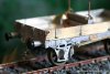
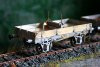
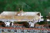
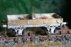
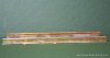
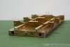
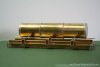
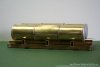
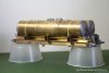
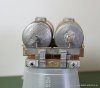
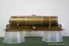
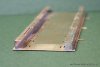
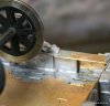
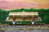
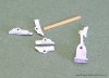
Photo shows a part built 7mm model from the top shelf, showing the end/ side arrangement in 'Timber' mode, although not yet the struts etc.
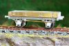
IMG_0001.JPG
 

jamiepage

Western Thunderer
The CR wagons do seem very capable of stone (ore) traffic with their fixed ends.
The bolster sits quite high to compensate (which seems stronger/ simpler than drop ends) and it does appear that the design would allow use in either role as modelled, simply by fitting/ removing the bolster as Rob suggests.
 

Rob Pulham

Western Thunderer
Last night I revisited the instructions and as far as they go, my interpretation is correct in that it's envisaged that the bolster and it's support would be removed for carrying ore.
 

Rob Pulham

Western Thunderer
As I mentioned in my last post, the next job was to sort out the brakes which are one sided on these wagons - they usually ran in pairs giving access to a brake from either side.
This is what was provided in the two kits - the casting with the base being the Majestic offering and the rest came with the Dragon kit.
IMG_6689_zps676b1a0c.jpg
The idea being that you solder the brass strip to one of the brake shoes with a few spares in case of accidents.
Me being me, I didn't really fancy that so I went for a strip of scrap etch bent to shape and some modified etched shoes from the spares box (suitably filed to an approximation of the cast shoes).
My apologies for the rather poor first photo the camera kept trying to focus on something else.....
IMG_6693_zpsa41fa7b0.jpg
IMG_6697_zps74ec0963.jpg
I also managed to get the lever made up for one of them but the work bench "ate" the locking nut for the second so more scrap etch needed for a replacement.....
IMG_6692_zpse3ab5665.jpg
 

Attachments

  • IMG_6689_zps676b1a0c.jpg
    IMG_6689_zps676b1a0c.jpg
    129.4 KB · Views: 0
  • IMG_6693_zpsa41fa7b0.jpg
    IMG_6693_zpsa41fa7b0.jpg
    92.7 KB · Views: 0
  • IMG_6697_zps74ec0963.jpg
    IMG_6697_zps74ec0963.jpg
    119.1 KB · Views: 0
  • IMG_6692_zpse3ab5665.jpg
    IMG_6692_zpse3ab5665.jpg
    146.8 KB · Views: 0

JimG

Western Thunderer
Last night I revisited the instructions and as far as they go, my interpretation is correct in that it's envisaged that the bolster and it's support would be removed for carrying ore.

Rob,

I've just been digging through the Caledonian wagon book again and I think I've found the source of the description. At the bottom of Page 133 in the section about the Diag.48 timber wagon, Mike Williams refers to the wagon being "confusingly described as for timber and ore in the diagram book". I could ask on the CRA forum as to what is meant by "confusingly". :)

Jim
 

Rob Pulham

Western Thunderer
Last night saw the Timber and Ore Wagons completed.

IMG_6698_zpse42689f3.jpg

The chains that hold the sides up severely tried my eyesight and patience - my £7 magnifying specs really came to the rescue! The rings that hold the chains on the ends were spare rope rings from the Connoisseur sand wagon kit. The fine chain is from Slaters (David Parkins kindly pointed me at the source after using the fine chain in the MMP Glass Wagon).

IMG_6699_zpsd1fab1a2.jpg

IMG_6700_zps817d4108.jpg

IMG_6701_zpsb6a07955.jpg

On the one photo that I have seen there are quite prominent wagon plates on the sides. I am not sure if these were replaced by the LMS but I found four badly etched loco build plates that looked about the right size and added them. Once they are painted and lost under some weathering they should look the part.
IMG_6702_zps35204b9b.jpg

IMG_6703_zps1ae2be34.jpg

Next up is the paint shop.
 

Attachments

  • IMG_6698_zpse42689f3.jpg
    IMG_6698_zpse42689f3.jpg
    132.9 KB · Views: 0
  • IMG_6699_zpsd1fab1a2.jpg
    IMG_6699_zpsd1fab1a2.jpg
    95.4 KB · Views: 0
  • IMG_6700_zps817d4108.jpg
    IMG_6700_zps817d4108.jpg
    120.3 KB · Views: 0
  • IMG_6701_zpsb6a07955.jpg
    IMG_6701_zpsb6a07955.jpg
    124.5 KB · Views: 0
  • IMG_6702_zps35204b9b.jpg
    IMG_6702_zps35204b9b.jpg
    155.2 KB · Views: 0
  • IMG_6703_zps1ae2be34.jpg
    IMG_6703_zps1ae2be34.jpg
    142.2 KB · Views: 0

Rob Pulham

Western Thunderer
A quiet day at home resulted in my getting the timber wagons into primer - two colours no less. I have read a few posts about people using black primer for underframes so I gave it a go along with grey for the bodywork.
Then I made a start on the next one which is another Dragon kit. This one is the NBR/LNER 'twin' tank travelling gas wagon. I emphasise the twin because I have asked Chris Basten if he can supply another kit with an extra tank so that I can do a triple tanked version too.
This is another one that originated in the Majestic models stable and so far the tanks have made up very nicely. The only adjustment that I needed to make was on the outer tank wrapper which has two half etched edges to make a smooth seam. When I tried them the left too much of a gap between the wrapper and the cylinder so I cut of one of the half etches plus an extra 0.5mm this allowed for a much better fit and the slight overlap from the remaining half etched section is hidden under the tank.
What has come as a bit of a surprise based on the other former Majestic kits that I have built is that the bulk of it is etched (I had in my mind that the chassis was cast much like the 4mm SE Finecast versions that I built previously - perhaps that's where the false idea came from....).
IMG_6705_zpsa9b308eb.jpg
IMG_6704_zpsd5b2c927.jpg
All the rivet strips are separate items giving a nicely reinforced appearance.
 

Attachments

  • IMG_6705_zpsa9b308eb.jpg
    IMG_6705_zpsa9b308eb.jpg
    112.1 KB · Views: 0
  • IMG_6704_zpsd5b2c927.jpg
    IMG_6704_zpsd5b2c927.jpg
    102.3 KB · Views: 0

Rob Pulham

Western Thunderer
A busy week hasn't allowed much time to progress this but I managed a little last night.

The solebar overlays went on like a dream.

IMG_6731_zpsaa6bc0ba.jpg

The challenge came when I got to soldering the solebars to the underframe. The underframe has a broken half etched line to show where it's located but getting it to solder in an upright position tested my ingenuity. In the end a piece of rectangular tube backed up with a strip of scrap etch under the lip brought it vertical so I placed it under one end while I tacked in and then repeated at the other end before completing the seam.

IMG_6730_zps7aef5bbf.jpg
 

Attachments

  • IMG_6731_zpsaa6bc0ba.jpg
    IMG_6731_zpsaa6bc0ba.jpg
    74.4 KB · Views: 0
  • IMG_6730_zps7aef5bbf.jpg
    IMG_6730_zps7aef5bbf.jpg
    71.7 KB · Views: 0

Rob Pulham

Western Thunderer
The timber and ore wagons have been through the paint shop and are now at the transfer stage.

I had a little hiccup with the painting in so much as a large section of the pain on one side of one wagon came back of when I removed the masking. This is the first time that this has happened and I can only assume that I didn't do something right....

Instead of being dismayed I got stuck in and repaired it. This was achieved very quickly with the use of a hairdryer to dry off the paint in between coats - it took longer to clean the air brush between coats than it took to redo the painting....

IMG_6732_zpscad61e45.jpg

IMG_6734_zpsdd40803f.jpg

IMG_6735_zpsbcfa1284.jpg

IMG_6736_zps49ebe4c3.jpg
 

Attachments

  • IMG_6732_zpscad61e45.jpg
    IMG_6732_zpscad61e45.jpg
    118.4 KB · Views: 0
  • IMG_6734_zpsdd40803f.jpg
    IMG_6734_zpsdd40803f.jpg
    139 KB · Views: 0
  • IMG_6735_zpsbcfa1284.jpg
    IMG_6735_zpsbcfa1284.jpg
    127.7 KB · Views: 0
  • IMG_6736_zps49ebe4c3.jpg
    IMG_6736_zps49ebe4c3.jpg
    140.3 KB · Views: 0

Rob Pulham

Western Thunderer
Good progress has been made on the tank wagon over the weekend.

Everything went together nicely with the tanks held on in prototypical fashion via the strapping. The only bit I changed was the pipe fittings that come out of the ends of the tanks. There are nice castings supplied but I doubted that I could solder in a piece of rod for the pipes without melting the fine whitemetal tube so I modified a pair of Connoisseur clack valves - Once lost under paint and weathering they should suffice adn stand a bit more handling.

With a bit of luck I should have it on it's wheels tonight.

Here are a couple of shots of where we are to date - it still needs some cleaning up though.

IMG_6742_zps09d74548.jpg

IMG_6741_zps9b05d0a0.jpg

IMG_6740_zps6b26b80b.jpg
 

Attachments

  • IMG_6742_zps09d74548.jpg
    IMG_6742_zps09d74548.jpg
    76.6 KB · Views: 0
  • IMG_6741_zps9b05d0a0.jpg
    IMG_6741_zps9b05d0a0.jpg
    111.9 KB · Views: 0
  • IMG_6740_zps6b26b80b.jpg
    IMG_6740_zps6b26b80b.jpg
    73.1 KB · Views: 0

Rob Pulham

Western Thunderer
A complete lack of any energy this week (as opposed to lack of mojo) has meant that I didn't do anything further on the tank wagon until last night.

This is where I had to do the first major deviation from the instructions.

In the photo below the slots that you see in the bottom of the solebars hold the W Irons. The problem being that the flanges at the top of them are not deep enough to touch the underside of the floor and as they are, they don't sit flush with the back of the sole bars either. This means that if you were to solder them to the underside of the solebars then the thin strip on the inside would make them very prone to being bent out of position with very little to anchor them to.

IMG_6730_zps7aef5bbf.jpg

How I got around this was to solder four strips of scrap etch to the back of the sole bar and then solder the W Iron flange to that giving a nice solid fixing. I also found that I needed to file to points of the axle ends in order to make the W Irons sit upright without bowing outwards.

IMG_6760_zps8199ca09.jpg

Once I had this sorted getting the other wheels on was straightforward. Lastly I added the brakes. Which unless I have missed something, just leaves the brake levers/guards, the ends of the cradles and the vacuum pipes before a good clean up.

IMG_6758_zpsd2e2bdd2.jpg

IMG_6757_zpsa0dec8be.jpg
 

Attachments

  • IMG_6730_zps7aef5bbf.jpg
    IMG_6730_zps7aef5bbf.jpg
    71.7 KB · Views: 0
  • IMG_6760_zps8199ca09.jpg
    IMG_6760_zps8199ca09.jpg
    123.3 KB · Views: 0
  • IMG_6758_zpsd2e2bdd2.jpg
    IMG_6758_zpsd2e2bdd2.jpg
    133.3 KB · Views: 0
  • IMG_6757_zpsa0dec8be.jpg
    IMG_6757_zpsa0dec8be.jpg
    132.5 KB · Views: 0
Top