7mm A GE Side job

Rob Pulham

Western Thunderer
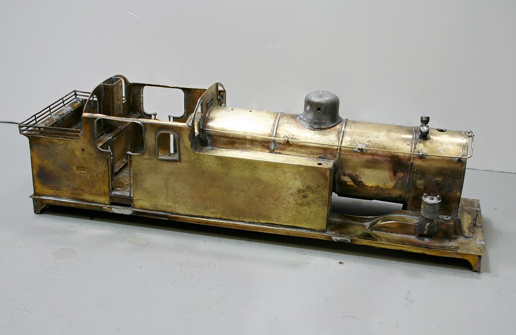
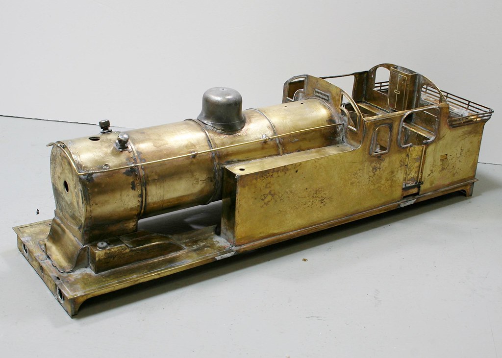
This one is a little different for me, the gent that I am building the J6 for is building a layout based on Hitchen in the late 1950's/early 1960's and N7's were there a plenty. He has several N7/5's but needed at least one N7/3 so he bought one already built via eBAY.

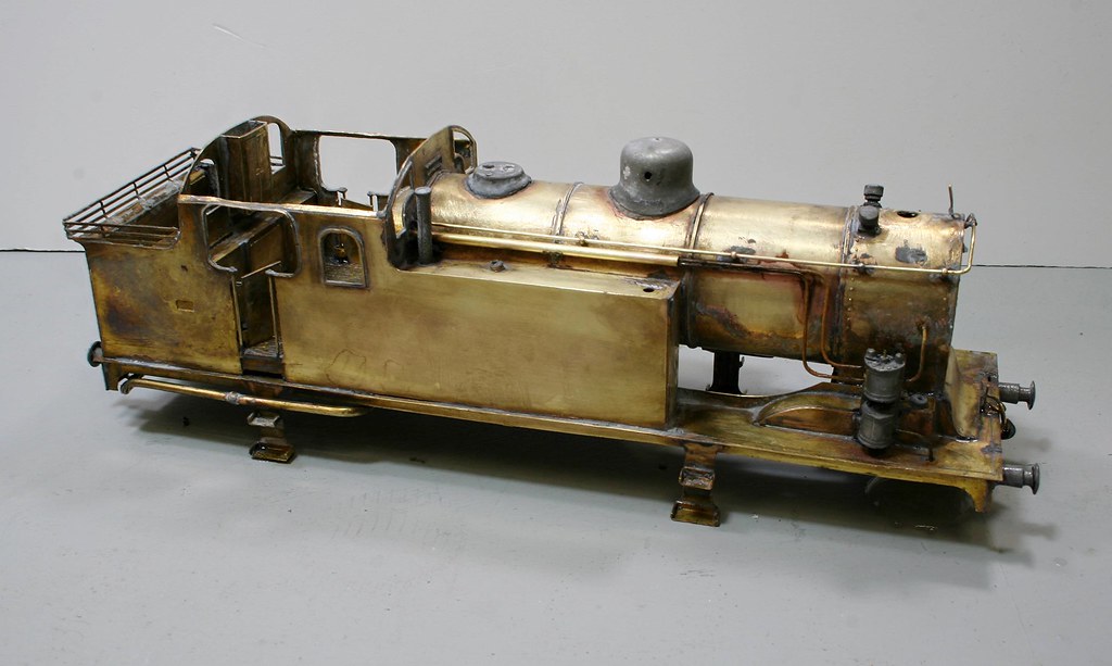
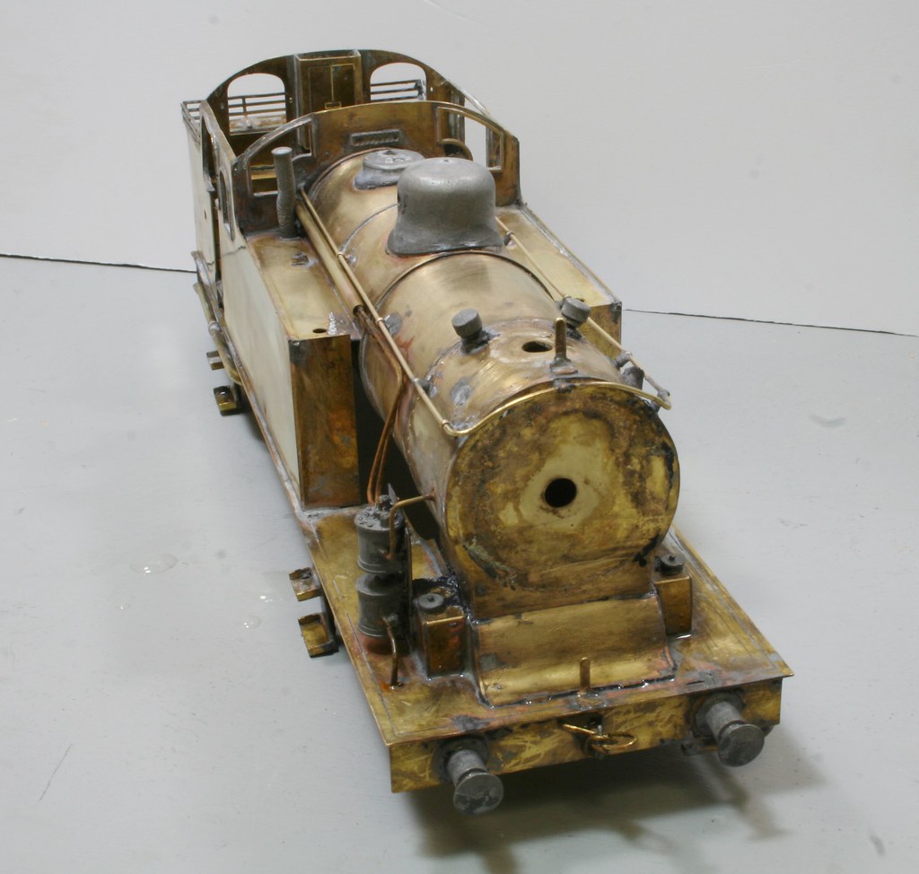
It's lacking some detail and has some that needs to be removed to build his chosen example

The photos below are as it came to me and are copyright of my customer and used here with his permission.

44828949054_99559f92b7_b.jpg


45554113001_961e2f7402_b.jpg


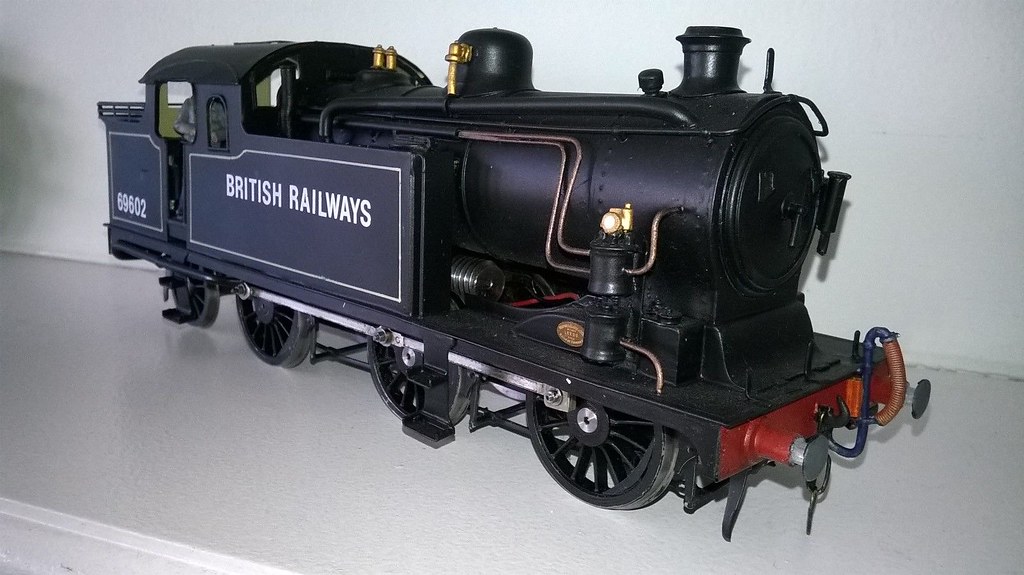
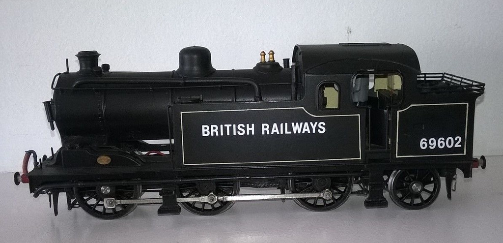
It's new identity is to be 69618 and I am working to a supplied photo of the engine as at 23rd May 1959

So far this is what I have observed needs to be done:

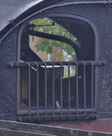
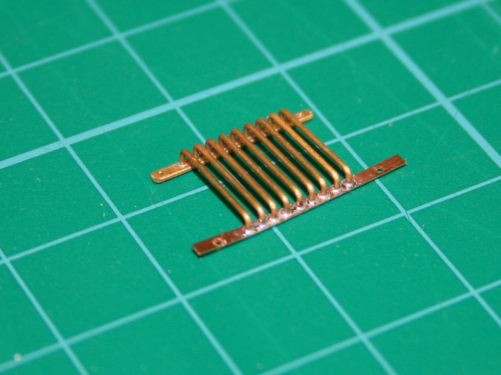
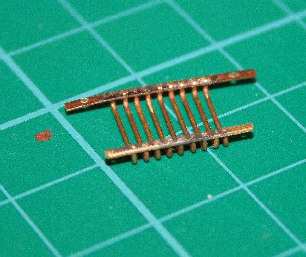
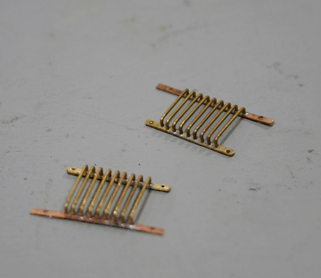
  • Window guards to rear cab - half height of windows
  • Condensing pipes - remove
  • Safety valves, remove base and refit/replace
  • Vacuum ejector pipe – boiler to cab
  • Remove valve from dome
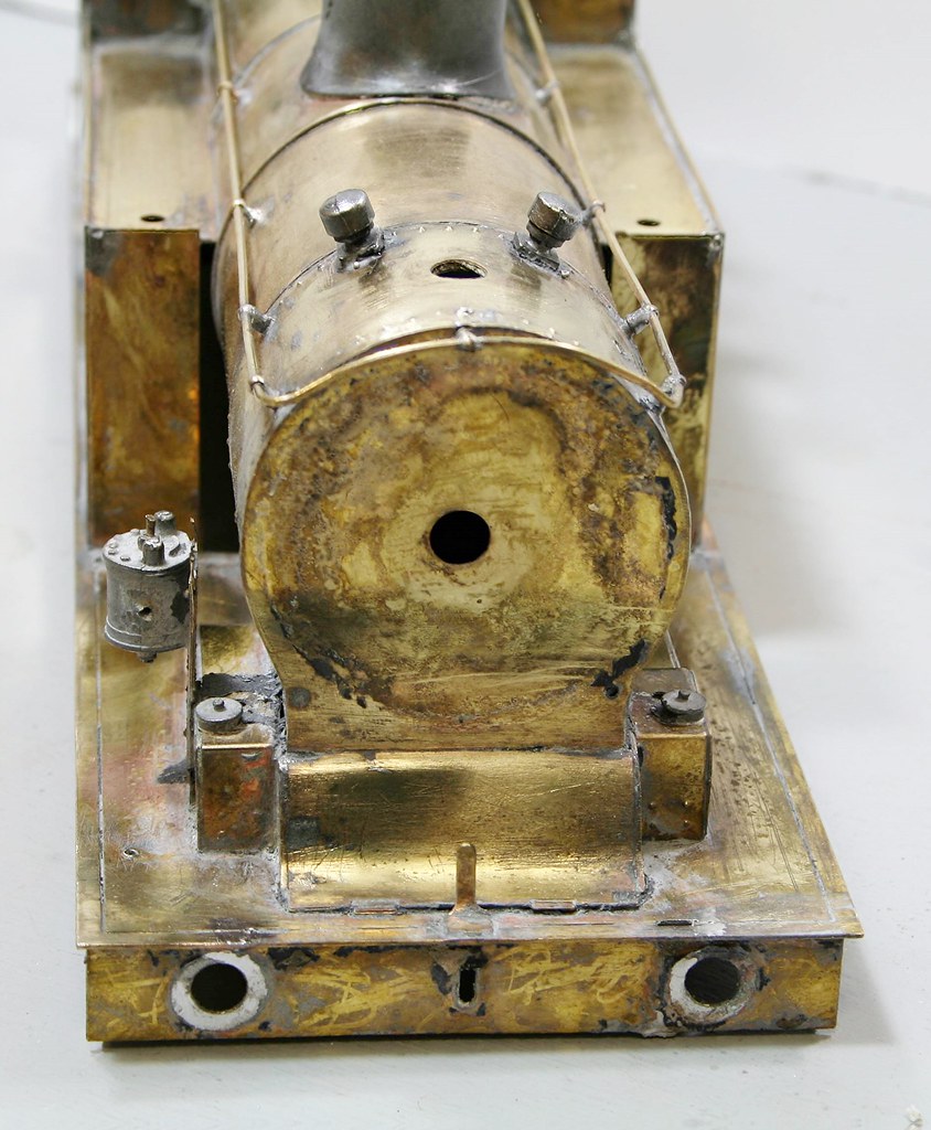
  • Hinge on smoke box door
  • Move lamp iron from top of boiler to smokebox door
  • Step on Piano front
  • Knobs on Piano front
  • Oilers under smoke box door – either side
  • Steps on tank fronts
  • Plate in coal rails
  • Glaze cab
  • Reversing lever and fittings under boiler to help disguise worm gear from motor
  • Move steps from outside of valance to where they should be.
Before going on holiday 3 weeks ago I bought 10 bottles of nail varnish remover from Wilkinsons (Wilcos) and left the body to soak in it while I was away.

Quite a few bits dropped off and others were coaxed to release their grip followed a scrub with Bar Keepers Friend got it to a point where I was able to use the microflame to remove other parts

43736508390_a14106358e_b.jpg


45503771192_bd745463b0_b.jpg
 

Rob Pulham

Western Thunderer
The application of a bit of heat removed a few more bits and pieces

45553954061_121685ffcd_b.jpg


45553953801_ec6d012748_b.jpg


45503769062_06af23d213_b.jpg


First thing on Friday morning I placed a biggish order for parts with Laurie Griffin and one with Walsall Model Industries for the Buffers.

The jury is out at the minute as to whether I replace the Westinghouse Pump with one from Ragstone.

Next job is strip the chassis down for it's dunk in the paint stripper.
 

Scale7JB

Western Thunderer
If you're really going for it Rob, I believe you may need to reshape the the leading bosses on the coupling rods..

Do check first though..

JB.
 

Rob Pulham

Western Thunderer
If you're really going for it Rob, I believe you may need to reshape the the leading bosses on the coupling rods..

Do check first though..

JB.

Thanks JB,

Looking through the Yeadon volume for the N7s, it seems that some had curved bosses and others had the rectangular type. Luckily the photo that I am working to has them of the rectangular type so I should be okay.

I do need to do some work on them because whoever built it didn't do a great job and you can see the individual laminations in some places. Nothing that some solder and a clean up won't fix though.
 

Rob Pulham

Western Thunderer
Rob

You’ll find a litre of Acetone from eBay rather cheaper than nail varnish remover from Wilko’s - and it won’t have lanolin or anything like that in it

Best
Simon

Thanks Simon,
I was in a bit of a hurry before going on holiday or I would have done just that (or gun wash thinner).
 

Rob Pulham

Western Thunderer
Despite cleaning up the N7 and ordering the bits for it the mojo has been a bit lacking since I returned from my jollies so I decided to have a play with my lathe to see if I could kick start the mojo.

My first effort turned to dismay when I found that the tail stock didn't centre on the work piece and then when attempting to turn a short length of brass rod, it was turning off centre - great for turning crank shafts perhaps but useless for what it's designed for.

All sorts of fears went through my mind from worn bearings to faulty chuck. So I started a bit of trouble shooting and having swapped the 3 jaw chuck for a Jacobs drill chuck I found that the running with that was concentric and I turned the thicker end of the example below. This left the fault being with the 3 jaw chuck. I very quickly deduced that when I have taken the jaws out to clean them I hadn't got them back right. I tried each combination in turn trying to get them to go back evenly by screwing them on but didn't have any luck. In the end I had to strip down the chuck by removing the mounting plate and then removing the circlip from the back to get the front plate far enough away from the back plate to allow the three jaws to slip over the spiral and into the centre equally spaced. Then I pushed the font and back plates together and reinserted the circlip. All looked well so I added the mounting plate and tried again.

Thankfully this seems to have resolved the problem and the other end it the result from using the 3 jaw chuck.

31732075038_4dc7ab57ee_b.jpg


Now by now you may be wondering what this has to do with the N7 and the answer is absolutely nothing, but it did restore my mojo. So being in a machine tool mood, I set to drilling out the buffer stocks for the fake mounting bolts.

A while ago I mentioned that I had a Proxxon Dividing head. Up to now I haven't actually used it but it was bought with this very thing in mind and it very quickly turned these

45604386101_8709f0067c_b.jpg


Into these

45604385681_a6cf48f96c_b.jpg


I then proceeded to make some fake nuts by filing hexagonal flats on some microbore tube
Using a pin vice as a guide - A technique that I picked up from Nick Dunhill, cheers Nick!

31732074738_eaf3b45a99_b.jpg


Once filed up short lengths were cut off using a scalpel and a piece of 0.8mm rod inserted into the tube. This rod was subsequently cut to length and soldered onto the buffer shanks to give these

31732074338_155d9e14a5_b.jpg


I took the photo when I had done two but all four were done before I packed in for the evening.
 

Dog Star

Western Thunderer
Re the three jaw, I expect the jaws to be stamped with a number (1 or 2 or 3) so as to identify which goes where in the body of the chuck. Are the jaws of your 3-jaw chuck stamped? (if not then might be worth marking them now).
 

Rob Pulham

Western Thunderer
Re the three jaw, I expect the jaws to be stamped with a number (1 or 2 or 3) so as to identify which goes where in the body of the chuck. Are the jaws of your 3-jaw chuck stamped? (if not then might be worth marking them now).

Hi Graham,

They are and so is the back plate but matching them up and trying all the different combinations didn't help (by that I mean, no1 in no 1 slot 1st, then no2 in no2 slot first etc.).
 

JimG

Western Thunderer
Hi Graham,

They are and so is the back plate but matching them up and trying all the different combinations didn't help (by that I mean, no1 in no 1 slot 1st, then no2 in no2 slot first etc.).

Rob,

If you engaged the jaws on the scroll in order - i.e. jaw 1 in its slot and engaging the scroll spiral, then 2 in its slot, then 3, they should be in the correct position. If not, then the jaws may be numbered wrongly. You can check that by looking at the placement of the teeth on the back of the jaws

ChuckJaws.jpg

The teeth on No.1 jaw should be closest to the gripping end as in the jaw nearest the camera in this shot of the jaws from my small Bison chuck. No. 2 jaw is next above and No. 3 jaw furthest away with its teeth furthest from the gripping end.

The teeth on this chuck are reversible, hence their shape, and when used in the outside orientation are not fitted in the 1-2-3 order. I always forget the order and have to work it out every time I need the outside setting. :)
 

simond

Western Thunderer
The teeth on No.1 jaw should be closest to the gripping end as in the jaw nearest the camera in this shot of the jaws from my small Bison chuck. No. 2 jaw is next above and No. 3 jaw furthest away with its teeth furthest from the gripping end.

The teeth on this chuck are reversible, hence their shape, and when used in the outside orientation are not fitted in the 1-2-3 order. I always forget the order and have to work it out every time I need the outside setting. :)

Jim,

3, 2, 1...

But you do have to get the start of the scroll aligned with slot 3, then back a tad, then start.

Best
Simon
 

JimG

Western Thunderer
Jim,

3, 2, 1...

But you do have to get the start of the scroll aligned with slot 3, then back a tad, then start.

But the jaw slots become 3-1-2 so that Jaw 1 is in Slot 2 and Jaw 2 is in Slot 1. That's the bit I forget. I'm too used to working with my Burnerd three jaw on the Myford with separate outside jaws. :)

Jim.
 

Rob Pulham

Western Thunderer
Rob,

If you engaged the jaws on the scroll in order - i.e. jaw 1 in its slot and engaging the scroll spiral, then 2 in its slot, then 3, they should be in the correct position. If not, then the jaws may be numbered wrongly. You can check that by looking at the placement of the teeth on the back of the jaws

View attachment 94280

The teeth on No.1 jaw should be closest to the gripping end as in the jaw nearest the camera in this shot of the jaws from my small Bison chuck. No. 2 jaw is next above and No. 3 jaw furthest away with its teeth furthest from the gripping end.

The teeth on this chuck are reversible, hence their shape, and when used in the outside orientation are not fitted in the 1-2-3 order. I always forget the order and have to work it out every time I need the outside setting. :)

Hi Jim,

They are as you show but no matter which number leading, I tried I couldn't get them back so that they all centred. They are fine now that I have centred them again by easing the back plate so that they slid over the scroll spiral. - Hopefully I won't need to take it apart again - the jaws are reversible but I am not going to bother I don't think....
 

Rob Pulham

Western Thunderer
One of the more difficult aspects of the refurbishment of the N7 in my mind was the half height coal bars on the rear windows of the cab and I had been wracking my brains as to the best method of drilling the rear of the cab in situ to get the holes both in a line and equally spaced while not being able to get the drill bit at 90 degree to the workpiece.

At the same time I was also struggling from the photos that I had to work out just how many bars there are as luck would have it a bit of web surfing turned up a partial shot of the back of the cab back of the preserved engine and this a is a further snip of that showing my get out of jail free card

45633412642_32d8dc673c.jpg


This meant that I could make them off the loco and fit them as a single unit. Some time later making best use of the Proxxon mini drill and coordinate table, had me with two pairs of strips each with 9 x 0.5mm holes 1.2mm apart. The eagle eyed will also note that I have put additional holes in each end for the retaining bolts.

Before packing it in for the night I had the first one soldered up ready for fitting.

44769738165_f74c9f8911_b.jpg


45633412962_5b16cf2e4b_b.jpg


I just need to do the other and then I think that I have broken the back of the difficult bits so I will return to the J6 until the rest of the parts orders arrive.
 
Top