A West Midlands Works

Scanlon

Western Thunderer
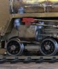
At last I have a 4-6-0 again. The engine steps have been built up and fitted and detail work around the cylinders finished. Yet to fit are the long drain pipes from the cylinder cocks. The major work has centred around the brake gear. The castings for the hangers and brake blocks were very chunky and despite chamfering the back of the blocks I could not get a decent let alone prototypical finish to them. There was nothing for it but to remove the brake blocks in their entirety, they will be replaced with Slaters LMS brake blocks which look very similar to the Southern version. Before each block was removed I drilled out the cast locating pin to ensure the replacement blocks are in the correct orientation. This photo shows the before and after look prior to refitting the pins and tidying up.

Brake Hangers 160815.JPG

So far only the hangers and stretchers have been fitted, Lord Nelson brake gear is a nightmare to build and fit but it has to be done.
These photos below show the build to date.

Loco 6 160815.JPG

A totally unexpected problem arose with the centre driving wheels. When I put the frames under the body this axle locked up completely. Using a spot light I eventually diagnosed the throat plate casting for the front of the firebox was much too wide and rubbing on the back of these wheels. Judicious use of the Dremel and a slitting disc has got rid of that problem and now all wheels revolve and I've got sideplay back on the middle driving axle.

Loco 7 160815.JPG

Thanks to Ragstone coming up with the correct battery box, it's the same as fitted to the Britannia pacific's, I've decided to fit the AWS especially as the cabsides have the two holes etched into them for the AWS. Outstanding work on the engine is now centred around completing the brakes, fitting the injectors and installing pick-ups plus building the boiler backplate. The latter will be delayed as I'd like to improve the overall look by incorporating some of the new Hobbyhorse castings.

Once the brakes are finished the frames can then be prepared for spraying and once that has been achieved the valve gear will be built and installed.

Now where is that GWR 2021?
 

Scanlon

Western Thunderer
Work on Lord St. Vincent has now reached the quiet stage. Injectors and damper linkage have been installed and there is only minor work to complete on the frames. The major piece of outstanding work is on the boiler backplate which I will only be able to finish detailing after Telford.

So being at a loose end this is what I knocked up today.
Frames 3 210815.JPG
These are the frames for a Scorpio 2021 Pannier tank which I'm building for a friend. It will be 2069 which lasted at Birkenhead until late in the 1950's. I like the Scorpio kits although a bit of care is required to produce a good model. As usual I built the frames on my chassis jig starting first with the coupling rods, this photo shows them before and after cleaning up. They are the usual three piece etch but only construct rigid rods, fortunate as I'm building a rigid frame.
Rods 210815.JPG

After cleaning they required minimal work to get them to fit the jig and work could proceed apace.
Frames 1 210815.JPG
The nickle silver used for the frames is very flimsy but with spacers, ashpan and various other fittings in place they have become fairly robust. By this afternoon I had a rolling chassis ready for testing as the layout it will run on has rather tight radii. Until I am happy they will negotiate the curves I won't do anything else to them. The loco is supplied with a full set of non working whitemetal inside motion but the instructions say they are a challenge to fit. Don't hold your breath!

Depending on the trial running work will resume on the frames or I might start the body.
 

Scanlon

Western Thunderer
Progress on my builds has been nicely interrupted by Telford and helping Dikitriki to run Heyside. I met a few Thunderers but missed some whom I had hoped to thank personally for their help on recent projects. As for the show, I saw very little of it due to my commitments but a quick scan of the layouts showed the standard has been raised yet again.

With Heyside back in its home I have returned to my Lord Nelson. A few colleagues had mentioned the cab roof seemed to be sloping towards the tender. Of course they were correct and the roof overlay was taken off and the rear strengthener inside the cab removed. Using set squares I ensure the cabsides were vertical and then set about rebuilding the roof which now is level.
Loco 8 100915 (1).JPG
On the frames the pipework for the injectors has been completed. Although I had previously installed the brake hangers and stretchers I was very unhappy with them, simply the stretchers were far too long causing the hangers to "bow" out. Each stretcher was removed and reduced in length, instead of a one piece casting each has become three pieces. Great care was required to reinstall them and not melt the new joints. This work has produced a huge improvement and the appearance is greatly enhanced. Now I have to install the brake actuator gear, not a job I'm looking forward to given its position and the many fiddly parts. At the suggestion of previous builders of this kit I have reduced the depth of the splashers behind the crossheads. This is to allow the bogie more sideways travel to negotiate 6ft curves. In addition an AWS protector shield has been added to the front bufferbeam and the conduit for the AWS and the speedo added to the drivers side valance. The AWS battery box will be added after painting and lining because on 30856 it is located partly in front of the drivers side rear splasher.

The tender required only minimal additional work. The rear bufferbeam has been detailed and the brake cylinder and associated actuator equipment fitted. The tender is now finished and awaits painting.

I am hoping to complete the frames in the near future and then to strip and paint them. With this job out of the way I can reassemble them, install the valve year plus pick-ups and start the process of running in. The frames have already been tested under power with just the coupling and connecting rods and all was OK so hopefully installing the valve gear will be relatively straightforward. Time will tell!
 

Dikitriki

Flying Squad
Using set squares I ensure the cabsides were vertical and then set about rebuilding the roof which now is level.
At the suggestion of previous builders of this kit I have reduced the depth of the splashers behind the crossheads. This is to allow the bogie more sideways travel to negotiate 6ft curves.

Hi Roger,

I'm glad you sorted the cab roof, the lean back did stand out.

My solution to the bogie splasher problem was to make a new splasher top, and move the whole thing out as far as I could. I think I left the side intact.

Cheers,

Richard
 

Scanlon

Western Thunderer
Thanks Richard for your help with the bogie splashers, I've got it wrong so may have to live with my botch! Today I decided to tackle the boiler backhead. Some very good castings produce an excellent representation of the real thing, here is my effort plus a photo of the real thing, courtesy of Ian Allan
IMG_2990.JPG
This represents a whole day's work, preparing fittings, bending pipework and soldering in place, finding it does not fit, so back to stage 1 and so on. The pipework from the vacuum brake to the floor had to be changed a number of times to avoid conflicting with the reverser. With everything in place there is just about 1mm wiggle room to get the backhead in place.
IMG_2989.JPG
It is not quite finished as I'm waiting the appropriate Detroit Lubricator from Hobbyhorse. Once received, it's on the way, I can complete the pipework and tidy up all the soldered joints and fit operating wheels to the various valves The pipes on the right hand side of the backhead for the injectors and steam heat will be trimmed when final fitting takes place, their lower ends being hidden by the dampers.
 

Scanlon

Western Thunderer
Lord St. Vincent has got to the paint shop stage. It took over an hour to dismantle the frames and then clean them up. After allowing for drying and masking up I got down to spraying them in primer. The next day everything was in top coat black which was allowed to harden off before reassembly and fitting the valve gear etc. could start.

Reassembly included fitting pick-ups on the engine and tender and on the former these had to be discreetly fitted onto the top of the flanges but fit under the splashers. A bit of trial and error was required before a satisfactory arrangement was reached. On the tender the fixed axle within each bogie has been fitted with pick-ups to improve overall performance.

This weekend I have constructed and fitted the valve gear and given it a thorough test on the rolling road
IMG_3029.JPG
Normally I enjoy building an fitting valve gear but this loco proved to be a trial. The components are very delicate etchings and it proved near impossible to keep stray solder away from locking everything up. On the fireman's side the valve gear had to be stripped down twice before it would work properly. Having got over this frustration the driver's side went together without a hitch. There is very little left to do on the loco, fitting brake blocks, speedo crank, cylinder cock pipes and finish off the cab and then it is away for painting.

Lord St. V is my weekend work and weekdays are given over to other work and progress on 2069 has taken a leap forward .

Following the instructions the rivets were pressed out on the valances, then I looked at the photo of 2069 that had been sent to me. No rivets! So they had to go. I pressed them back as far as possible and then filed everything flat. I’m quite happy with the build so far as laminating the various parts together has gone quite well given the upper laminates are nickel silver and the main assembly is brass. The chosen loco does not have half the rivet detail that is provided in the kit so I’m busily filing etched rivets off to make the build as accurate as possible (Birkenhead 1959). The bufferbeams are most interesting as I’ve never come across a loco where the top of the beam is above the running plate. The lower edge is level with the underside of the valance but on the front I’ve had to drop it about 1mm so the buffer housings will fit under the running plate! There was no problem with the rear one. Fortunately buffer heights have not been compromised.

Before starting the running plate I completed fitting the remaining brake hanger brackets on the frames. A couple of the castings were badly formed and Scorpio replaced them. On reassembling the wheels and coupling rods I found all of the brackets fouled the rods! Two solutions came to mind move the brackets inwards or by far the easier was to put spacers behind the coupling rods. I decided to sleep on this problem. The next day I looked at the brake hanger brackets versus rods. It was no contest, the brackets could not be moved inwards without seriously compromising running on any type of curve. The kit does not provide any etched washers for the side rods but fortunately I had some in my spares box, moral being never throw anything away. The rods are now proud of the brackets but only just and further testing of the frames was required. Fortunately everything passed this second test.

With this job out of the way I started on the splashers which are quite detailed as they have brass beading and small whitemetal covers to clear the tops of the coupling rods.
Running plate 4 250915.JPG
The next job was to start building the cab and lower firebox, generally there was no problem. All went together nice and squarely thanks to my little set square! Following this the reversing rod and the sanding rods were installed. The latter were quite a challenge as the operating levers required 0.5mm holes drilling through them but all went well. The front bufferbeam has had the buffer castings installed and the lamp irons fitted. On the fireman’s side running plate there are three lamp irons for spare lamps a la the real machine.

Work then turned to the bunker. The castings for the top corners are not very good. I have a lot of work to do on them to make the bunker look presentable and this will require the rivet detail to be removed but they will be replaced using rivet transfers.
Loco 4 250915.JPG
Attention then turned to the pannier tank, not an easy construction but thankfully patience paid off and very little reworking was required. The tank is supposed to sit above the lower firebox but of course it did not. The cab front has a raised etch showing where the tank must sit so out came the trusty Dremel and now it fits! The photos show everything in place but not finally soldered in position.
Loco 5 270915.JPG
It also shows an issue on the top of the pannier tanks, namely you can see the thicker metal between the half etch on the upper curves. This was not noticeable until now and I do not know how to get over the problem. I think some wet and dry might be the answer as I’d rather like to avoid using filler, but it may come down to that in the end. The location is difficult because the handrail knobs are very close to the curve. Bah!
 

Scanlon

Western Thunderer
The little 2021 Pannier Tank is almost finished. A few days of decent weather allowed the frames to be sprayed and then reassembled. This was quite straightforward and wiring and pick-ups then installed. The latter were a challenge as there is very little room on such a small loco, they could not go on top of the wheels as they shorted out on the splashers so I ended up fitting them in line with but opposite the brake blocks. To eliminate the chance of shorts developing each pick up has been insulated with heat shrink material.

The problem of the thicker metal showing through on the tanks was dealt with using 250 grade wet and dry eventually ending with 2000 grade for the final finish. Thanks everyone for suggestions how to avoid this problem in future. With this job out of the way the tank could be detailed, this was followed by building the cab interior and finally making up the roof. The roof is a fine half etch and required some strengthening as it proved very susceptible to deformation. The boiler backhead is from the Laurie Griffin range as are the vacuum and steam heat pipes.
Detail 081015.JPG
The photo shows a cast smokebox door but this will be replaced with a door plus fittings from Warren Shephard's range. Once this is fitted final tidying up will take place and then it is into the paint shop.
Loco 14 081015.JPG

The next build is a Caprotti Standard Class 5 from the Severn Models range. In reality this is one of the former Jim Harris range. At the request of the client the fittings will be replaced by parts from the Ragstone range. Construction has started with the tender, to ensure the inner frames were level and square they were built up on the chassis jig.
Frame 1 091015.JPG
Frame 2 091015.JPG
I decided to build the tender according to the lessons learned from previous builds, so threw away the instructions, OK I kept the diagrams. Each of the basic units to build the tank were prepared as separate items and then assembly would follow. For once the top curve is spot on and there are no rogue rivets, a tip I learned from Dibateg. I spent hours looking at BR1C tenders to ensure the rivet detail was correct. Before building up the tender the cupboards and shovel plate were installed. As usual the curved roof over the cupboards was too short by about 3mm but this problem was quickly overcome with a bit of scrap etch.
Tender 1 101015.JPG
Proper construction started by fitting the rear of the tender to the fireman's side of the tank, with this at right angles I then detailed the rear by fitting lamp irons and handrails. Next came the tender front which was slightly tricky to fit. With this properly in place the coal space was made up but left fitting it until the basic box was finished. With a rigid box the whole assembly was fitted to the external frames.
Tender 2 101015.JPG
and
Tender 3 101015.JPG
Now to start the detailing process. From past experience the brake gear will be a trial but it has to be done. At least when finished 90% is hidden!
 

Scanlon

Western Thunderer
It has been a while since I last posted but there has been some progress. The DJB Standard 3 tank has finally gone back to its owner following lining etc. Similarly the little 2021 tank has been finished and is now at her new railway. This was a Scorpio kit and built up very well, frankly it was a joy and some Thunderers were doubting my sanity!
Croftdown.jpg
The owner will be fitting British Railways transfers in the very near future prior to weathering.

So work is now concentrated upon the Caprotti Standard Class 5. Progress has been slow but it is starting to look like the machine. The frames built up quite simply with no issues until the cylinders were inserted in their slots. As components they fitted perfectly but built up they took on a mind of their own. With a lot of patience they eventually fitted properly. A further issue arose with the cam box casting which is correct for the right hand cylinder but not for the left! Consternation; a discussion with the kit manufacturer established they did not have a casting appropriate for the left hand cylinder. Fortunately a fellow Thunderer suggested 3D printing and "flipping" the image to produce the required cam box. This is work in progress.

With the frames at a standstill work has turned to the engine body. Probably the only problem so far was getting the boiler round. It was supplied pre rolled but had to be flattened out and rolled again. It took a few days to get it truly in shape. The smokebox was no problem and at least got the front of the boiler circular! The firebox built up well and the front casting fitted with only a minimum of cleaning up. Of course there has to be a but, the cast in ring was much smaller in diameter than the boiler. Small "pips" of whitemetal were added around the ring and then gently filed down to achieve the correct diameter.

BR Standard cabs are always a trial and this one was true to type. A large amount of fettling was required to get the roof to the correct profile.

Putting the boiler assembly into the frames was quite simple although with the cab correctly at 90⁰ there was a small gap at the top of the firebox. When fitting the beading your correspondent slightly squeezed the gap and the cab was about 0.5 mm out of true.
Loco 2 081215.JPG
To rectify my own mistake took a good few hours but hopefully you will agree it is much better now.
Loco 3 112115.JPG
All fittings are from the Ragstone range and they are slowly being installed. With a bit of luck next week will see the manifold and all its pipework installed plus much more.
 

Scanlon

Western Thunderer
Circumstances have dictated railway modelling had to be set aside for a few months but now I have time to get back into the rhythm of loco building once again. However a few weeks ago I found time to meet Paul Moore who has painted and lined my Lord Nelson, 30856 Lord St. Vincent.
Paint 3a 070216.jpeg
This loco requires the brake gear to be reinstalled and the electrics connected and then a test hauling a train.

Meanwhile on the work bench is the Seven Models Caprotti Standard 5 and a major problem had arisen with poor castings for the cam boxes. The whitemetal castings were very poor and had to be replaced. Alan Buttler of ModelU came up trumps and magnificent new cam boxes have been produced, but more of that later.

While replacement cam boxes were being investigated detailing work on the engine body proceeded. The Ragstone fittings were cleaned up, not much to do here, tried in place and then pipe runs made up This is an aspect of modelling I love and very quickly the body began to take on its own character.
171215 (2).JPG
An unusual feature of the Caprotti engines is the additional steam supply from the dome to the cam boxes. The kit makes no provision for this so a scrabble through my whitemetal spares produced some GWR clack pipe covers and a GWR top feed. The latter was cut up to provide the connection to the dome and the pipe cover delicately formed to the new radius of the boiler. Much of the detailing is now finished with just the steam heat valve drain pipework and the steam lance cock and pipework to install.
Valve Gear 3a  010316.jpg
Usually I like to fit the injectors to the engine body but this is not possible on this loco. The lubricators are mounted on a frame alongside the lower firebox and the exhaust injector pipework is fitted to this frame and under the lubricators
73129 at BN (12).JPG
Currently I'm working on a bracket to support the injectors and their associated pipework to be fitted on the frames. This is still work in progress.

So now to the valve gear and the cam boxes from ModelU are the "bees knees". They have been produced from NRM drawings and the detail on them is superb.
20160207_142813.jpg
Being accurate reproductions these boxes are considerably smaller than the whitemetal castings so I knew some issues might arise fitting the valve gear.

Firstly I made sure the chassis ran properly and this required resetting the slidebars followed by rebuilding the connecting rods. Once this was accomplished I started on the left hand valve gear and as expected this proved to be a pain. Usually I would start from the cylinders and work backwards but on this build I had to work from the opposite direction. With the cam box in place the reverser rod and its mechanism is correctly in place, but the connection to the valve gear was too short. Looking at photos of the real machine there are two sets of universal joints on the "valve rod", the kit only has one set modelled but I found another set. How was I going to fit all the bits together? Glue or solder? I decided to sleep on this problem.

This morning I decided against the idea of trying to glue rods together. I went out to my local model shop and bought some 1.8mm OD tube, soldered the universal joints onto the rod once cut to size and this is the result.
Valve Gear 2 010316.JPG
and
Valve Gear 3 010316.JPG

The return crank end of the valve gear has yet to be fully soldered into place, its slightly too low. I can only do this once the frames etc. are almost finished and the return crank is in place but this is work in progress. Tomorrow I might get the other side built and then can turn to the lubricator assembly, fitting the injectors, fitting brakes and energising the motor. Lots still to do.
 

Scanlon

Western Thunderer
I need some help, has any other Thunderer attempted to build one of these locos? I have got this far with detailing the fireman's side
Loco 5 080316.JPG
There are some major problems still to resolve. The exhaust injector steam pipe should be horizontal so I’m going to cut the whitemetal casting, level up the rear and fill the gap with whitemetal; relatively straightforward. Then there are the rear steam pipes on the cylinders. This photo shows what the finished article should look like
73129 at BN (18).JPG
The castings are supposed to go behind the two operating rods, the upper is the reversing rod and the lower is the valve rod. It then should be in front of the slidebars (just) and fit level with the front of the cylinder. Not a hope! I 'm considering removing metal from the rear of the casting to fit in front of the slidebars and to create a slot to accommodate the valve rod and get the casting as far forward as possible. I foresee a lot of basic Anglo Saxon, burnt fingers and much filling. Has anyone a sensible alternative to fitting these castings other than throwing the thing away!!


Thanks in anticipation.
 

dibateg

Western Thunderer
Another 3D print... Challenging stuff Roger! Try filing the hell out of the castings first, I had to do that with some of the Crostie components...

Regards
Tony
 

Scanlon

Western Thunderer
Thanks Tony for your thoughts about carving up the steam pipes on the rear of the cylinders, I'm still pondering!

As you will have seen from earlier photos the fireman's side valve gear has been installed. Upon completion and when viewed from above the valve rod was at a different angle to the reverser rod. Both were in line on the driver's side. Out came the measuring sticks and low and behold you will not be surprised to learn the fireman's side support for the valve gear was 1.5mm longer than on the other side giving the loco a bandy leg look. The trusty Dremel sliced through the support, a strip of nickel silver was then soldered on top of the part still fixed to the frames to ensure the correct height, length and alignment was maintained and then the remaining part reinstalled. Now everything is in line.

This was the start of a number of problems on the fireman's side of the loco. The bracket for the lubricators was too long for its intended location. With the lubricators temporarily in position a dry run proved the leftward "leg" wanted to go between the wheel and frame, not good for running. So the casting was modified and then two Ragstone lubricators complete with lost wax castings for the ratchet gear added. I had to cut off the delicate operating arms as these were far too long for this loco.

In the previous post I mentioned the issue with the level of the exhaust injector pipework. This pipework had to be installed under the lubricator frame as it would dictate the position of the exhaust injector. Frankly this was wasted effort as I decided to measure up scale drawings to produce a framework for the injectors. With this built and the injectors installed I had forced the exhaust pipework to fit; wrong. Today the pipe was cut and the resulting gap was about 6mm
Injector 2 110316.JPG
I filled this with 100⁰ whitemetal and then filed the offending joints back to restore the pipe.
Injector 3 110316.JPG
Minor fitting work has continued with sandbox covers, the step on the firebox side and minor pipework installed.
Loco 9 110316.jpg
Next week it is brake gear, pick-ups and lots more, oh joy.
 

Scanlon

Western Thunderer
Quite a bit has happened since my last post. On the Caprotti Standard 5 most work has been concentrated on the frames, cylinders and cab. I decided against using the cast brake gear for the engine as it appeared far too chunky, instead the etches were used. These assembled beautifully and give a much better appearance to the loco. As usual the leading brake stretcher interfered with the swing of the bogie and to overcome this I thinned it down without affecting the overall appearance.

The cylinders were a nightmare, well to be specific the rear steampipes were. A number of discussions with fellow Heysiders gave me loads of options most of which were discarded as I was not confident I could achieve a satisfactory result. In the end the leading steampipes were soldered in position and the rear pipes were "adapted". The huge casting would never have fitted into its intended location so I cut off the steam pipe from the lower part of the casting. I then soldered the "exhaust" outlet part of the casting in its correct location and finally soldered the blanked off steam pipe behind the valve rods. This was a poor compromise but at least something was achieved as this photo shows.
Cylinder 160416.jpg
The build is now almost complete and the loco has reached this stage
Loco 20 230416.JPG
The frames have not been thoroughly road tested, I only have a short test track with reverse 6ft curves. While this is adequate, running on a layout through pointwork etc. is critical to iron out any gremlins that might be lurking around. Hopefully a full test can be arranged in the near future and then the frames can be adjusted if required and painted.

So now I'm on to my next build, a David Andrews 47XX. I have started on the tender and this has built up beautifully. Pick-ups have been installed on all wheels and the build has reached this stage
Tender 7 230416.JPG
Hopefully the tender will be finished this weekend and then I can turn to the engine.

This photo shows the engine frames have been built but not by me. They were built by David Amias who reduced the width to give greater side to side clearance as the loco has to negotiate 4ft 6" curves
47XX 230416 (1).JPG
Testing the frames on its intended home layout identified a number of issues. The frames are fully compensated and whilst the second axle has considerable side play there was a major problem with the third and fourth axles. Thought was given to fitting non flanged wheels but I can hear your screams at this idea. Eventually a solution came about.

The side rods were acting as "springs" keeping the long wheelbase quite rigid. I decided upon using an idea gleaned from the German Kriegsloks (Class 52). The rear axle crankpins on these locomotives are longer to allow the bearings in the rods much greater side play. New longer/deeper bearings were fitted to the crankpins on both axles, the side rods had the bearing holes slightly eased to allow more freedom of movement and they were also reduced in thickness. The frames were reassembled and tested on my 6ft curves but they did not perform very well. Further investigation showed the rods were striking the brake hangers at their upper fixing points. To overcome this the hangers on the rear two axles have been moved further in to the frames. The result was a much better running frame although the plastic brake blocks are slightly tighter on the flanges. A test on the home layout was made and thankfully these modifications seem to have worked.

I plan to build up the running plate which have the splashers sides as part of the etch. The modified frames will then be retested to ensure the wheels do not strike the inside of the splashers and cause shorting out. If they do the splashers will have to be moved out. So watch this space.
 

Attachments

  • Cylinder 160416.jpg
    Cylinder 160416.jpg
    165.7 KB · Views: 10

Scanlon

Western Thunderer
The tender of 4701 is almost there, just lamp irons to fit and those pesky corners on the rear of the tender raves to have more tlc to get them right.
Tender 8 240416.JPG
A very successful trial run of the engine frames, running plate and tender has been accomplished so now work is concentrated on the engine body. Generally everything fits together very well although the cab did prove to be a tour de force. Set squares were used to ensure the cab sides were horizontal, the cab front was then installed and everything soldered up. Then a start was made on building the boiler. These are the components just to build the firebox.
Firebox 1 260416.JPG
As usual this was a trial of strength which the kit was winning at the start but eventually I triumphed! As many of you know the problem with most fireboxes is the number of reverse curves that have to be created and these eventually fight against one another plus the builder. In comparison the boiler section is just three etches plus a pair of nuts and bolts, the smokebox is similar.

With the three parts bolted together the smokebox was not level, I just had to take a little out of the bottom of the boiler at the lower front and this did the trick. However there was a further problem, the rocking shaft detail inside the frames appeared to be too tall and was stopping the whole assembly from going into its correct position. I had various plans to overcome the issue and eventually settled on cutting down the rocking shafts or reworking them slightly lower in the frames. Thank goodness for a good night's sleep as the next morning I realised the inside motion had been installed incorrectly. Once this was correctly repositioned the boiler sat perfectly in position. With the three sections properly assembled they were soldered in position and boiler bands added.

I am now at the slow stage where some parts are glued onto the body and time allowed for the glue to cure. A lot of work has been concentrated on the cab with amongst other items the floor, dragbox and roof built up.

Detailing the smokebox saddle gave a few problems which took some time to resolve. The outside steampipes would not fit properly with the casting representing the saddle bolts in place. The latter came off and the steampipes correctly located. The saddle castings were then thinned down and put back in position. This is the current state of play
IMG_3466.JPG

As last weekend was a holiday I decided to treat myself and start on an ex SECR D1 4-4-0 for my own collection. I have got this far and can tell you building the Collett tender was much easier. As usual the tender inner frames have had pick-ups installed.
Tender frames 010516.JPG
This kit has oodles of half etches which have to be sweated together before building into the basic body. Very fiddly but at least it now looks like the beast it is supposed to be.
Tender 4 030516.JPG
Next weekend should see the tender finished and tidied up.
 

Scanlon

Western Thunderer
Roger,

There are some problems with the tender, especially it's underframe. I suggest you don't look here: BR(S), SR, SECR L-class 4-4-0

Steph
Too late, I've already looked!!!!!!!!!!! Just hope the engine is not as bad. I will crib some of your ideas but doubt I'll undertake a complete rebuild especially as I don't propose my loco being viewed upside down too often, if at all!
 
Last edited:
Top