Bracket Signal

oldravendale

Western Thunderer
I have, indeed, found 4mm quite challenging, Jon, after building locos in 7mm for so long. I think I'll stick to 7mm from now on, though. My eyesight is starting to let me down. I'd actually have found this impossible without the help I've had on this thread.

Brian
 

oldravendale

Western Thunderer
Before I forget, thanks to everyone for all the help without which I'd not have achieved this. I'm not quite home and dry, but I'm absolutely convinced that I'll get there now. Sorry that it's been so long to update but each step has been tiny (as, indeed, is the model itself).

Anyway, here we are now.

100_0286.JPG

This is the reverse view, lamps and brackets in place, trimmer brackets fitted, finials fitted, step boards cut and applied and weighted lower cranks fitted. The whole signal has been fitted to a brass base which the sparks will equip with appropriate servos.

100_0303.JPG

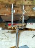
Now the complete ensemblage from the front, with a signal arm in place just because I can. The rather oversize signal cranks are in place here - I took the decision to make these of sufficient dimensions to ensure that the signal arms will work. Subsequent to this I've fitted the operating wires (photos to follow) and up to the point where the rods to the signals are in place everything works. I'm ecstatic!

100_0297.JPG

This is the operating cranks at the lower end of the signal with their counterweights.

100_0304.JPG

And this is the detail of the front of the signal and those over size operating cranks. These have two 0.8mm washers with holes opened up to o.5mm for the rods which are from dressmakers pins behind the cranks to give space for the operating wires, and one washer at the front. The movement is good.

100_0305.JPG

Finally the prepared stanchions for the hand rails. The verticals are from 0.5mm wires with the ends compressed in a machine vice. These flattened ends have been drilled 0.4mm and the copper wire, 0.35mm, will be threaded through these. Since taking the photos I've fitted one of the uprights and it all works. The final appearance will be up to my dexterity.

BTW, the two single signals with which I started this missive are now painted and ready for final assembly, fitting the servos and installation.

Brian
 

Attachments

  • 100_0296.JPG
    100_0296.JPG
    107.6 KB · Views: 6

Jon Fitness

Western Thunderer
Looks like a lovely job Brian. I think you've just about got it boxed off now as the difficult jobs are done. Will it be MR era or more recent?

JF
 

oldravendale

Western Thunderer
Thanks Jon.

It's to go on a mid 1950s layout. All the signals bar this one are upper quadrant. We just fancied a change, but this is probably the first and last in 4mm! I may consider more 7mm for club if needed though.

Brian
 

Jon Fitness

Western Thunderer
Thanks Jon.

It's to go on a mid 1950s layout. All the signals bar this one are upper quadrant. We just fancied a change, but this is probably the first and last in 4mm! I may consider more 7mm for club if needed though.

Brian
Ah good, so no daft looking yellow and brown signal posts!
JF
 

oldravendale

Western Thunderer
Here's where I'm up to now.

Ladder fitted. Handrails are fitted around the staging. I worked on these for what felt like hours to try to straighten them out. Then I looked at some photos and discovered that the prototypes were all bent to hell.:)

This evening it's all been washed/neutralised (my standard hot water/washing soda/ aluminium foil mix, then rinsed by brushing in running water. If time allows tomorrow I'll prime in white, then it's just a smattering of black and red paint to complete.

(Of course, I'm ignoring the wires to the signal arms, the clips over the tops and the addition of the servos, but you now what I mean).

100_0307.JPG 100_0308.JPG 100_0309.JPG

These photos show quite graphically the tip I call my work bench. You'll no doubt be dismayed to learn that all has now been cleared and put away in the correct locations, such that I'll not now find what I need when I need it, whatever it may be. Except that the rolls of solder and epoxy resin remain out on the bench.:))

Brian
 

oldravendale

Western Thunderer
I was just a tiny bit concerned that someone would say that! I'll consider the options, but discretion may be the better part of valour at this point in the construction. I guess the sensible thing would have been to make the dolls lower.......

B
 

oldravendale

Western Thunderer
Please don't apologise, John! All the clues to the need for another ladder were there. We'll just have to imagine that the lamp men are 8 ft tall. (Actually, in scale reality a six footer might just about manage to trim the lamps, but only just - that viewpoint in my photos is from above the signal and the perspective makes the main post look shorter than it actually is. I will measure the scale height of that longer doll, though).

Brian
 

oldravendale

Western Thunderer
When an error is pointed out I always do this.......say that I'll not correct it and then it gnaws away. So, it's all your fault, Jon!:)

I dun it. Added extra ladders. I measured the height of the lamps and I'd have needed a lamp man of a minimum 8 ft tall, and another of 6 ft tall. Those who know me will be aware that I can't afford to be heightist so ladders it had to be. I also did a fair bit of research this afternoon, reviewing my three signaling books and looking on line. All this was no help whatsoever as it appears that there was no standard or convention about how to deal with additional ladders from the staging even though I checked MR signals alone. In fact (as Jon will be well aware) sometimes there was an additional ladder from ground level. Goodness only knows what the complications will be if I start looking at signals from other railways.

Anyway. The common approach seems to be to add another stage adjacent to each lamp. However, sometimes not. And sometimes from the lamp side, and sometimes not. And sometimes from behind the signal. And sometimes with safety loops and sometimes not. (But as we at TCMRS are good employers we'll at least provide safety loops. And we're scared of the H & S police.) But as I had the perfect get out I didn't have to provide a stage, so didn't!

I also had to manipulate the guard rail around the existing staging to give room for a lamp man to get around the ladders.

This is the result:

100_0310.JPG 100_0313.JPG 100_0315.JPG

Brian
 

Jon Fitness

Western Thunderer

oldravendale

Western Thunderer
Truly thanks for your help Jon. This would not have been completed without (not to mention other help as well!)

No photos today. Paint is drying in the workshop now. Hopefully reassembly of the whole thing tomorrow.

B
 

oldravendale

Western Thunderer
The job is done. There are one or two compromises which will give the aficionados something to complain about when the layout goes on display, but my response to them will be to ask how many 4mm signals they have built!!

Final painting was Halfords rattle can white primer over all, then Humbrol mat black, gloss signal red, a sort of brownish colour for the staging and white to touch up the bits chipped and damaged during the final painting. The signal lenses were made (for the first time) using Microscale Micro Krystal Klear to fill the lens aperture and then painting with food colouring mixed to produce the cyan/green colour. The red was a pretty good match to the gels straight from the bottle. This is a great deal easier than trying to cut gels to size and then fit to those tiny apertures. Unless you or your good lady are in to cake decorating already purchase of a suitable range is only a few £s and will last for ever.

Firstly the last pair of single upper quadrant signals (I have already made one pair which are on the layout already). These are from MSE parts, although one of the signals already in situ has been built using an SSS kit. There are some benefits to the SSS kit as the whole operating block and spindle comes as a lost wax casting and it is an easier option than trying to solder tubes and wire in to place on a white metal column.

The photos show that I've failed to trim the operating wires back as far as I might, but that'll be a quick and final job.

100_0326.JPG 100_0327.JPG 100_0330.JPG 100_0331.JPG

Now the lower quadrant bracket. I notice that I've failed to balance the arms entirely the same, one to another, but the servo adjustment will put that right. Neither should both arms be cleared at the same time!

100_0317.JPG 100_0318.JPG 100_0322.JPG 100_0323.JPG

To return to my initial post: I have no knowledge of signals and would now build with more refinement and knowledge of the subject. However, this exercise has proven that an initial lack of knowledge should not be any sort of barrier. The kits, if built as designed, create a very passable representation of the real thing. When you have to build something a little more bespoke there are a few books freely available which are an enormous help, but where there are any queries this group is an enormous help. In fact without the help I've received the build would have been far more protracted.

Brian
 

Jon Fitness

Western Thunderer
They all look superb Brian. I've been "off line" for a few days so I am just catching up. A bit of weathering to tone the white down a bit and they'll be a lovely addition to the layout. Cracking job.
Cheers
JF
 

oldravendale

Western Thunderer
Thank you Jon. From you in particular that's a great compliment.

That's a very good point about toning the white down. I'll leave that to the layout builders - my brief is "factory finish" but I'll point out that they are just a bit bright as they stand.

Brian
 

oldravendale

Western Thunderer
I'm resurrecting this thread because I'm currently completing a 7mm MR bracket for club before I start on the "Royal Scot". This is where I am at the moment.

IMG_20200617_135652536.jpg

As I said at the beginning of this thread, I have no knowledge of signals and rely on the instructions and photos to help me through. I built one 4mm example from Scale Signal Supply previously. but this was a single post affair and was quite straightforward. This is another barrel of worms entirely and I have to say that, for one of limited knowledge such as myself, the instructions are really quite inadequate. (Jon - I believe you use Scale Signal Supply components quite a lot in your builds, but you know what you are recreating. I don't.:) Also the signals I've seen which you've built are illuminated...... this one won't be!)

Some of the more complex shapes are quite nicely cast, although they need fettling to get in to shape and for them to fit. I've now reached the staging and there doesn't appear to be anything in the kit which reproduces this. I'm going ahead and making my own from scratch. Once this is done I hope that the major challenges are over. One area which is very good, IMHO, is the signal operating system with its designed in cranks and these operate well.

Having now had experience of both types I can safely say that I find the MSE instructions easier to follow and more concise. They also give helpful info about post heights and other dimensions. Having said this I think this kit will build a perfectly respectable signal at the end of the day.

I think this will be ready for primer/undercoat and, indeed, top coat in some areas when the staging is done.

Pics of the finished item will follow...... Critiques are always welcome.

Brian
 

Jon Fitness

Western Thunderer
I do use SSS parts, and I like that they are mostly cast in brass. Gives me much more confidence when I'm wielding a soldering iron. To be honest, I've actually never built this kit as I've always scratch built by LMS structures but it looks like you've made an excellent job of it. The cross shaft system of working the arms is fun to set up. I think I prefer it to other companies' wheels and cranks etc.
 
Top