Building the MOK "King Arthur"

adrian

Flying Squad
Here's where I could do with a bit of advice. All those large brass castings have to be fixed to the cylinders. I always prefer solder. The problem with that is that the use of sufficient heat will probably cause the cylinder wrappers to pop. My thought, therefore, is to attach them with 5 minute epoxy. ...
Suggestions on a postcard regarding the fitting of the castings, please.....

As recommended by @Thirtysecond Loctite 326

An amazing adhesive
 

oldravendale

Western Thunderer
I considered Loctite before going down the 2-part epoxy route, Adrian. My reason for choosing to not use Loctite was because I wanted to be able to separate the parts if I got anything wrong. Separating an epoxy join is possible, if a bit of a faff, whereas I don't think anything will separate a Loctite joint. I also benefitted from the time it takes for the epoxy joint to set, allowing almost infinite adjustment time.

Anyway, cylinder backs with slidebars are now fitted with epoxy. Seems to have worked OK. They will now be cleaned up and other solid brass components fitted in a similar manner. Possibly even some photos today.......:)

Brian
 

oldravendale

Western Thunderer
Nest stages.

Completing the cylinder/motion bracket etc assembly. All the large bits of brass have been fixed with 2-part adhesive. This is a very clever combination of etches and castings. There's a bit of origami involved but with care the result is exceptionally good. The whole unit comes away from the frames and clips in to place before fixing with screws in captive nuts.

IMG_20200325_144131561_BURST000_COVER.jpg
Next came the cylinder drain cocks. Lotsa bits but they look good. There's a bit of finishing of this stage to complete but they are essentially complete.

IMG_20200325_170849928_HDR.jpg

Next I start on the motion.

Brian
 

oldravendale

Western Thunderer
I think I need confirmation that I have all the up and down and round and round bits in the correct order. Regrettably this is one of the areas where Dave's instructions could be, let's say, expanded.

IMG_20200329_144339934_HDR.jpg

This is the dray run. Just want to check---- That bit sticking out of the top is the lift link. There's no indication what will prevent it flapping around in the breeze but I suspect this will go through the footplate and join up with the lift arm from the reverser. Does that sound feasible? (Or perhaps even correct?)

IMG_20200329_144422888_HDR.jpg
Also, I believe that the link block on the expansion link fits in to the expansion link bracket and is held in place by the pins running through it. Below is a close up of the expansion link bracket and the lower one shows that Dave has cleverly incorporated a removable section (displaying part number 225 in the photo below) in to which the pins of the link bock will fit.

IMG_20200329_144459114_HDR.jpg

I finished the coupling rods today so will fit wheels and check that the chassis works. Thereafter the return crank has to be sorted. I'm thinking that a bearing tapped to 10BA and soldered to the reverse of the return crank and a 10BA screw through the wheel, coupling rod bearing and return crank bearing will do the trick. I just have to work out how to make the fixing at the back of the wheel so it can be tightened but removable. Possibly a simple countersunk screw cut to length? But then the whole assembly depends on the screw through the wheel. Hmmmm.

Brian
 

oldravendale

Western Thunderer
Aah! You noticed my deliberate mistake!:rolleyes: I intended these to all be correct and representative of the finished article, although nothing is fitted yet - all the pins are loose or a jam fit. That was a significant error on my part and will not appear thus when I get everything together.

B
 

oldravendale

Western Thunderer
I have to say, Roger, that it's a most enjoyable build, because everything fits! You have to make some of it up as you go along but it's great fun if you have even a modicum of knowledge and experience. I possibly just fit in one of those categories! You may not want an N15 for yourself but there's plenty of people out there who'll cross your palm with silver for a built one.:)

I last built Dave's Q1, as you'll probably remember, and this is every bit as good.

B
 

oldravendale

Western Thunderer
Just to update.....

Fiddly works! The oil pots have been fitted to the top of the slidebars and the sandboxes to the motion brackets. Although cast nicely in brass the sandboxes took a deal of tidying up and were the very devil to locate so that sufficient heat could be applied without undoing all the other soldered joints. The oil pots were just hugely fiddly to fit. Dave suggests a superglue to fix these but I'm sure that would be inadequate so they are fitted with a medium temperature solder.

IMG_20200401_153141851_HDR.jpg

The backs of the wheels have been polished and they have been chemically blackened too. The coupling rods are now completed too. Tomorrow I'll test fit the wheels and coupling rods and have a look at clearances behind the front wheels. (Looking at prototype photos the coupling rod bearings seem to be countersunk at the front, so some 10BA reversed and tapped bearings may be the best option). The cast bits for the brake rigging are also separated from the sprue and partly cleaned up. If I'm lucky I'll get the clean up of the brake parts completed and perhaps a dry run.

Brian
 

oldravendale

Western Thunderer
So..... Wheels are fitted. I found they are tight to the springs which tended to rub. I fitted an 0.7 mm washer each side which was too tight. But an 0.4 mm washer each side worked perfectly. The chassis in this state was checked through a reverse curve and everything was good with perfect operating clearances.

IMG_20200402_161937553_HDR.jpg

A further review showed very limited clearances elsewhere. In fact in the region of half a standard gnat's crotchet. Maybe even less.

Look at those blow up pictures below and the clearance between the driving wheels and the brake hanger pins. But the clever thing is that the wheels actually clear them! I suspect that with a bit of static we'll see some interesting light shows.
IMG_20200402_162106102_HDR - Copy (3).jpg IMG_20200402_162106102_HDR - Copy.jpg

At this point I should hold my hand up to a cardinal error. In fact it was a decision I made to start with. The whole chassis was built without any reference to the made up coupling rods. I know that chassis should always be made using the coupling rods as the reference. This, for me, is the ultimate test. I've only just made up the coupling rods, made a clearance fit for the rod bearings and fitted them to the wheels. Worked first time. Well done Dave Sharp.

Please don't do as I do, just do as you're meant to do!

IMG_20200402_171721319_HDR.jpg

Brian
 

Attachments

  • IMG_20200402_162106102_HDR - Copy (2).jpg
    IMG_20200402_162106102_HDR - Copy (2).jpg
    178.4 KB · Views: 6

richard carr

Western Thunderer
Brian

No surprise there about the coupling rods, both of my MOK kits were built like that and worked first time with very little clearance required.

I'm just waiting for you to say that they are the best kits on the market !

Richard
 

oldravendale

Western Thunderer
Hold on a minute!! I'll reserve judgment for now but MOK along with a couple of others I can think of fall in to the same general bracket. These are quite remarkable from a one man operation for sure although the instructions let the general excellence of the kit down here and there.

My Q1 went together in much the same way. I'm looking forward to getting it back from Paul Moore so that I can test it out in anger, but when we'll be able to meet again I'm uncertain.

Brian
 

oldravendale

Western Thunderer
Apologies for the intermission...... Valve gear isn't my strongest suite.:)

Additionally the valve rod was damaged. I assumed this was simply bent back at its weakest point, but when I came to straighten it I found that the bent back bit was fixed in place, so clearly a casting problem. I spoke to Dave Sharp who's sending a new one but I didn't want to be held up and made an effort to effect a repair. Here's as it arrived:

IMG_20200327_140420052_HDR - Copy.jpg

And here's as it was when repaired.

IMG_20200407_152147897.jpg

So I then went ahead with the valve gear. One or two hiccups along the way but finally completed. I'm impressed by the way the whole assembly can be removed from the loco via the detachable cylinders.

IMG_20200415_141906687_HDR.jpg

Amazingly, and down to the design, when the loco was tested with valve gear in place it ran perfectly well without any lubrication yet.

Next job is the injectors. Then it'll be on to the boiler and bodywork.

Brian
 

oldravendale

Western Thunderer
Looking at my last post I was wondering what had taken me so long. Well, for sure the valve gear was a trial but then I realised I'd not discussed the brake gear, so here it is.

IMG_20200416_142807081_HDR.jpg

It takes a while to get all the clearances set up. The underneath of my locos will never be a Nick Dunhill or Mickoo but a) I don't know enough or have the ability to read a drawing which would enable me to do it and b) I have no idea what goes from where to somewhere else! (And I can't see it anyway) and c) I don't have a block of holes like Nick. In typical Dave Sharp fashion the brake gear comes off the loco in a complete unit.

This is where we are now - well, not strictly speaking as I've started on the boiler which again, in typical Dave Sharp fashion comprises loadsa bits, but I'll cover that later. Here are the injectors. The pipework is based on the excellent photos from the book of..... There are no drawings in the instructions to help with this aspect.

IMG_20200416_142851065_HDR.jpg IMG_20200416_142906878_HDR.jpg

Just to end with here's the completed engine, bogie and rear footsteps, sans footplate, cab and boiler. To my inexperienced eye this looks really good compared with photos of the prototype. And it works too.

IMG_20200416_143423665_HDR.jpg

Brian
 
Last edited:

Steph Dale

Western Thunderer
Dad,
I think Sir Sagramore had Ashford injectors by the time she was withdrawn, not the original exhaust and hot water types you've modelled - are the others in the kit? If not, is the chuffing great pipe off the front of the exhaust injector included - it should run into the back of the cylinder block between the frames?

Steph
 

oldravendale

Western Thunderer
Hmmmmm.

I have insufficient photos of Sir Sagramore to comment. You may well be (probably are!) quite correct. I've used the injectors as provided in the kit (they are the only two), one described as live steam and one as exhaust steam. Looking at the photos in the instructions I think Dave has taken a lot of the details from Sir Lamiel. However, I've been through all the photos in "The Book of....." with great care. These injectors are right for the "King Arthurs" at some stage in their lives. I have prototype photos of both sides of "King Arthurs" showing the injectors from the kit. Whether the period is correct or not is another matter! And certainly not all the locos had these injectors.

The poetically described "chuffing great pipe" is present but ceases at some where under the cab or firebox. I didn't (and don't!) know where it should go, so it terminates where the casting ends. A chuffing great pipe could potentially be seen behind the wheels but I don't think it'll be missed - certainly not by me. Additional edit. :) If you look at the photo of the underneath of the loco in my previous post you can see the end of the chuffing pipe on the extreme right hand side.

As we know, the tender is not absolutely right and the loco won't be either (although I didn't know so). In fact I think the tender probably had air tanks at the time the loco was withdrawn.

So.... I'll not change anything but it's good to know the shortcomings.

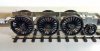
Today I've been doing battles with the boiler. The design made good sense to me and I built according to Dave's instructions. However, when checked against a straight edge the two sections were "on the wonk". I had to separated the two parts again, clean up and start again, measuring everything along the way. I made some very minor adjustments to the way the two parts sit together and I think it's probably OK now. I also found (as described a few times previously by Mickoo) that the thick nickel silver was the very devil to roll. These smaller sections were not too bad, but the big boiler section (no photo yet) was quite difficult. I've finished it around a piece of 1 inch water pipe.

IMG_20200417_140804420_HDR.jpg
Brian
 
Last edited:

Steph Dale

Western Thunderer
Fair enough, I know you're doing this as a straight out-of-the-box job, from our much earlier conversation about Urie vs. Maunsell variants of the tender...

Steph
 

oldravendale

Western Thunderer
I'll try to remember to copy the photos so that you'll know it's at least generically possible.:)

Just looked again at the photo I took of 30771 at Eastleigh. The injector on the right hand side is, as you suspected, not right for this loco. However, it's the only one in the box and from photos it would be right for other locos. I'm afraid it's going to stay as it is!
 
Last edited:
Top