7mm MK1 Brake Goods

farnetti

Western Thunderer
As I have (just about) finished the tank wagon and 16 ton wagon I had a choice of starting an 08 shunter or the brake goods.

Having decided on the 08 shunter I fell at the first hurdle. I folded up the inner frames and tried to solder laminate the strengthening pieces with the resistance soldering iron with no success. As I have mentioned before my traditional soldering equipment, lathe, airbrush, other kits and kitchen sink are all in storage for the foreseeable future. It has gone back in its box until later.

So I start on the BG, to be finished in BR maroon to fit in with my early 60's theme. It is constructed with lightweight bogies, twin bolsters, bottom routed brake linkage and without bogie steps. (Thank you to Bob and others for their help).

Although she didn't use them Heather has posted photos of the bogie etches so I won't repeat them. I'll post photos of the other etches as I come to them (if I remember), they are quite thin and I wish to handle them as little as possible. I have to say they are quite exquisite, no wonder called them a box of delights.

Anyway, down to business.DSCN1141.JPG

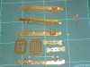
This shows the inner and outer bogie side frames and inner hornblocks cut out, rivets punched and folded to shape.

DSCN1147.JPG

Inner and outer bogie sides in more detail.

DSCN1144.JPG

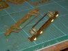
Here they have been soldered together and the small end fillets been cut out ready for soldering. Also shown are the first two parts of the bolster ready for folding and the phosphor bronze springs.

DSCN1149.JPG

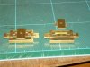
On the left hand side parts 3,4,5 and 6 folded, except for part 5. I found on the wagons trying to create reverse bends very close to each other was not easy so decided to solder parts 5 and 6 before creating them.
On the right hand side 3 and 4 soldered together, 5 and 6 soldered together.

DSCN1150.JPG

Parts 5 folded and on the left all soldered together.

Sorry about the photography, the flash seems to dominate when there is no natural daylight.

More in a week or so.

Ken
 

Attachments

  • DSCN1144.JPG
    DSCN1144.JPG
    1 MB · Views: 6
  • DSCN1147.JPG
    DSCN1147.JPG
    988.7 KB · Views: 6
  • DSCN1149.JPG
    DSCN1149.JPG
    1,005.1 KB · Views: 5
  • DSCN1150.JPG
    DSCN1150.JPG
    994.9 KB · Views: 5

farnetti

Western Thunderer
Had time to carry on today.
DSCN1152.JPG
For those building these bogies these are parts 7 & 8 at the top, and part 9 at the bottom. (It's the same for those not building them but I am not sure what to call the parts).

Where parts are to folded into a box shape, as part 8 above, I file the edges of the bits that will meet to a 45 degree angle to avoid any distortion at the corner. Parts 9 have had the rivets formed and the folded to shape.

DSCN1154.JPG

These parts have now been fitted to the previous assembly. There are cast rubbing plates to be added to the top of part 8 but I like to Araldite castings as late as possible in the hope I won't melt them.

DSCN1157.JPG

As these will be a twin bolster bogies the 8 parts to the left will need to be added. There is a choice of bolster springs provided, cast as top right or the long spring in the middle. Neither looked right but then I found the long spring is made of soft material which will easily compress as shown to the right of the original. With a bit of tweaking this should give around 4 turns per spring as per the prototype. The small parts to the right, some folded, are only added if not using the cast springs.

DSCN1161.JPG

This piccie shows the etched parts from the previous photo soldered in place.

Ken
 

farnetti

Western Thunderer
Now we have parts 45, 46 and 47. 46 and 47 are laminated and fixed to inner parts in the previous photos.DSCN1163.JPG

I had a small problem with parts 45 on the right. The instructions show them laminated which need 16 and only 9 are provided, Simon Varnams pictures show a casting. A reply from an e-mail to MMP says only 8 are needed so that is what I will do, they used to do the laminations but felt they were over scale. Full marks for the very prompt response from MMP.

Next I have soldered the sideframes to the bolster slightly ahead of the instructions.

DSCN1172.JPG

I did this because I am concerned about melting castings. As I only have the resistance soldering iron and solder cream available I am aralditing all castings. The next picture shows the rubbing plates waiting for the glue to set. Yawn!

DSCN1173.JPG

Whilst this is going on (or off) I have been making up the secondary spring pockets.

DSCN1176.JPG

The ones on the right and bits in the middle as cut out from the fret and on the left soldered and folded up.

I put a bit of extra solder in just for you Paul! Above I used about 0.5 cubic mm solder for each joint which was too much. Basically clean the surface with a glass fibre brush, resistance iron, Slaters No Clean solder cream (expensive but will last a lifetime) - that's it. No flux needed and a tiny, tiny amount of solder.

Ken
 

farnetti

Western Thunderer
Little bit more done this evening. Here I have araldited the secondary spring outside top brackets to the side frames.

DSCN1180.JPG

Next I have cut and filed to length the 16 rods that will fit into the outer and inner top brackets and through the cross members. I have also formed two of the 16 springs and are shown roughly in place with the rods in the bottom pockets. Will probably take all tomorrow evening to do the other 14. I've noticed there are differences in this kit compared with Simon Varnams pictures, castings under the bolster instead of etched parts and the spring material is now thicker, and to my eye more in keeping with the prototype.

DSCN1182.JPG

A good discovery today. I have been stripping out our recently purchased house ready for structural alterations and for the first time had to go in the roof of the old part. It is boarded out, has rafters to the ridge and purlins, that's it. At 4ft height there is 36 foot by 3ft baseboard area with enough full height standing room alongside. I don't have to buy a shed after all.
 

farnetti

Western Thunderer
I am departing a bit from the instructions here before I add the springs. The bogie feels a bit fragile at this point and so will finish the frames first. The photo shows those parts cut out, riveted and folded.

DSCN1209.JPG

Top left end frames including one with cut out for the dynamo belt and brackets for brake shoe hangers. Top right inner cross frames much the same. Below are the A frames that sit between them.

What I am wondering about (or maybe just wandering about) is that 1st and 3rd A frames shown have cutouts for the dynamo pulley and associated brackets even though only one would have needed them. Would that be the case in about 1960-2 i.e before bogie recycling? Or should I just use 1 bracket and fill in the cut out on the other frame?

Any help here much appreciated,

Ken
 

djparkins

Western Thunderer
I am departing a bit from the instructions here before I add the springs. The bogie feels a bit fragile at this point and so will finish the frames first. The photo shows those parts cut out, riveted and folded.

View attachment 38525

Top left end frames including one with cut out for the dynamo belt and brackets for brake shoe hangers. Top right inner cross frames much the same. Below are the A frames that sit between them.

What I am wondering about (or maybe just wandering about) is that 1st and 3rd A frames shown have cutouts for the dynamo pulley and associated brackets even though only one would have needed them. Would that be the case in about 1960-2 i.e before bogie recycling? Or should I just use 1 bracket and fill in the cut out on the other frame?

Any help here much appreciated,

Ken

Ken -

From the kit instructions:

"Form the bogie end beams from parts 22 & 23. Note that normally only one bogie of a pair would have an INNER end beam with the slot included for the dynamo belt [part 22]. As bogies were switched round as available, it was thus quite common to see an inner end beam with the slot for the dynamo belt on BOTH bogies. We therefore include two end beams with slots in case you wish to portray this situation. In either case you should ensure that the beam/s with the slot are fixed at the INNER end of the bogie/s - adjacent to part/s 19"

Thus the reason for adding the cut-outs to TWO of the A frames. OK - so you don't need the cut-out on the A frame at the non-dynamo end in most cases but visually it hardly matters so I would just fit and ignore it - OR fit the end beams with slots to both bogies [two provided]. There was not room to put in FIVE A frames so I thought it better to include the cut out on both of the relevant frames rather than not.

DJP
 

farnetti

Western Thunderer
David, as you say it won't be seen once the bogie is fitted and understand the limitations of space on the fret.

But in the spirit of Western Thunder and this kit I thought try and do my best. As I am modelling the coach circa 1960-62 I was thinking bogies wouldn't yet have been swapped around much. So will fill it in and not use the outside strengthening bracket.

Once again, many thanks for the prompt customer support.

Ken
 

farnetti

Western Thunderer
Have finished the parts above and fitted them to the bogies.

DSCN1212.JPG

Rubbish photo I know but shows the parts being assembled. Keep hinting to my wife we need a better camera than our 10 year old point and click but distinct lack of enthusiasm on her part.

DSCN1215.JPG

Now soldered to the bogie and everything feel much more substantial. I think the red colour at some of the soldered joints indicate I was using the wrong tap on the RSU. Anyway they all sit perfectly on a piece of glass.

Tomorrow I hope to finish the secondary springing and a few other small pieces and so back on track with the instructions.

Ken
 

farnetti

Western Thunderer
DSCN1216.JPG

The secondary springs now fitted. It was an interesting exercise to cut 16 of these to the same length and file the ends so they sat flat in position and were vertical. I had to do it by hand but a better job could possibly have been done with gently filing the ends in a lathe at a low speed (suitable handle on the tang of the file).

DSCN1222.JPG
Primary springing added. This is a bit tricky as it is important to get the central position of the spring at the correct height. I messed up on the first one and remedial work will ensue but easy thanks to the usual generous supply of small parts by MMP. I am going to spring my axles which involves fitting small phosphor bronze etches over the spigot and into a pocket previously formed in the frames. The axleboxes then rest up against these and so space must be available for them to flex although it only needs to be 0.5mm or so.

I have cut out most of the brake gear and linkage ready as it is possible that it maybe easier to fit some of this before the wheels. But the horn guides are next.

Ken
 

farnetti

Western Thunderer
Just as a guide a thought it would take me a month to 6 weeks to do these bogies. I was away in Portugal for 5 days and I am going away again later this week for 10 days (including Reading trade show). In the meantime I have been working on them about 1 hour or 1.5 hours a day (excluding WT stuff). So, without time away, and a bit of extra time I think I could have had them built in 3 weeks or so.

Anyway next piccies.DSCN1255.JPG
This shows the brake gear ready for fitting except for folds top centre. Much of this is laminated and tricky to do in the case of the yoke safety brackets.

DSCN1263.JPG
Here the bogies with the wheels temporarily fitted, dynamo pulley on one axle. There's a little bit of fettling to do here to get the axleboxes sliding smoothly and I still have to adjust the stops underneath the leaf springs. I am fitting the springing, it's all riding a bit high at present. The axleboxes need to be drilled out to accept the Slaters bearings and, as I am doing this to S7 recessed them as well to be flush with the inner face. The end of each axle will need shortening by about 2mm so the wheel hub is quite tight up against the bearing. It all seems to work great with little or no sideplay which hopefully means no shorting with the cast brake shoes (which I will coat with something anyway.

DSCN1262.JPG DSCN1259.JPG
I'm hoping to get some of the brake gear fitted before I go away but we'll see.

Ken
 

farnetti

Western Thunderer
Well I got none of it fitted then, and only a little in the last couple of days.

After reading the instructions and looking at Simon Varnams' pictures carefully I got it wrong. I attached a brake shoe to a hanger and put it in place in the appropriate bracket on the frames to see how it would fit against the wheel circumference and it didn't match at all. The hangers are very short and don't lend themselves to much adjustment after fitting.

So have decided to fit the brake hangers to the frames on one side only leaving them to move as Simon did, then temporarily fit the wheels and glue (I know) the brake blocks in place to match the curvature of the wheel. You will also see the brake yoke safety brackets.

I intend to fit the yokes, other safety brackets over them and then into the hangers on the other side (gulp). It means that, as the brake shoes are set slightly higher than the center line of the wheel, the wheels can drop out until the rest of the brake rigging is in place.

Tried to upload a picture from my new camera (at last) but file size too big. Walking day tomorrow so will sort it out when I get back, cooking duties permitting,

Ken
 

farnetti

Western Thunderer
Hi Richard,

As you say a bit awkward. The way I am doing it is to fit just the brake hanger to its bracket with wire as per the instructions, but making sure it is free to move. Place the wheels in position, some glue of your choosing into the slot in the brake show casting and carefully fit to the lower end of the hanger and against the wheel rim to set. Once dry the brake shoe and hanger will be free to swivel away slightly from the wheel, I have also smeared araldite onto the surface of the brake shoe casting to (hopefully) stop any shorting.

I do not think this method would be possible without glue, you would need to solder the casting to the hanger without knowing the correct angle and there is scarce room to get a soldering iron in place when the hanger, shoe and wheel are all in place.

It will be interesting to find out but it would appear, with care, that the brake gear will actually work as it should. However once I have it fitted it will be locked tight to avoid any potential shorting.

Ken
 

farnetti

Western Thunderer
And a little further on the brake rigging.

DSC_0042_01.JPG
The central pivot arm in place and attached to the long yolk above. The short yoke just fitted with second brake shoe below and waiting for epoxy to dry. The safety strap can be seen hanging loose just above the wheel and will be glued once everything else is set. It all seems a bit slapdash and out of order with the instructions but it is working for me and I can leave the final fit on the wheels until later so I have plenty of room for fitting the rest of the brake gear, and adjust the the brake shoes once the wheels are fitted. The safety straps are very delicate.

While waiting for the epoxy to dry I couldn't wait to get the underframe started. So I did. The fret is very similar to that on Heathers' thread Post 66. I have cut out parts 1, 8 and 9 as I intend to use 8 and 9 to hold the crossmembers in place while fixing. This has worked on the MMP wagons I have built and endorsed by Ian G and Ziderhead on Heathers thread. DSC_0045_01.JPG DSC_0046_01.JPG DSC_0044_01.JPG DSC_0047_01.JPG

The first picture is of the parts cut out and I expect to fold up and solder parts 8 and 9, the inner solebars to make them stronger before fitting them to anything else.

The lower part of the second picture shows the centre section of part 1 and the instructions say to fold up the brackets shown top left and bottom right. A half etch line seems to be missing (bottom right) but easy to create using a ruler and scrawker (top left).

Perhaps Heather, David or anyone else could help me with the last 2 photos. Parts 2 are shown in photo 3 with overlays and the instructions make it clear that they need to be 'handed'. But the slots in parts 8 and 9 (photo 4) are different widths. The overlays will fit in the wider slots or are the overlays only used with the wider (outer) slots. Brain probably not working well due to the excesses of Christmas.

Ken
 

djparkins

Western Thunderer
The lower part of the second picture shows the centre section of part 1 and the instructions say to fold up the brackets shown top left and bottom right. A half etch line seems to be missing (bottom right) but easy to create using a ruler and scrawker (top left).

Perhaps Heather, David or anyone else could help me with the last 2 photos. Parts 2 are shown in photo 3 with overlays and the instructions make it clear that they need to be 'handed'. But the slots in parts 8 and 9 (photo 4) are different widths. The overlays will fit in the wider slots or are the overlays only used with the wider (outer) slots. Brain probably not working well due to the excesses of Christmas.

Ken

Ken -

We only intended the overlays to be used with the outer girders but then I think we mis-counted by putting 8 in. Obviously you can use them if you wish though, by widening the slots on the outer faces of the slots. I assume they are present on the inner girders!

Regards,

David
 

farnetti

Western Thunderer
Ken -

We only intended the overlays to be used with the outer girders but then I think we mis-counted by putting 8 in. Obviously you can use them if you wish though, by widening the slots on the outer faces of the slots. I assume they are present on the inner girders!

Regards,

David
Thanks David, I sort of assumed so as well so will try to fit them.

Only trouble is I've seem to have lost my slotting file after 30 years of use. £23.95 to replace, I should look after things more carefully.

Happy New Year to everyone.

Ken
 
Top