7mm Rob Pulham's Work Bench - Back (again) to the LNER 06 (MOK 8F)

Rob Pulham

Western Thunderer
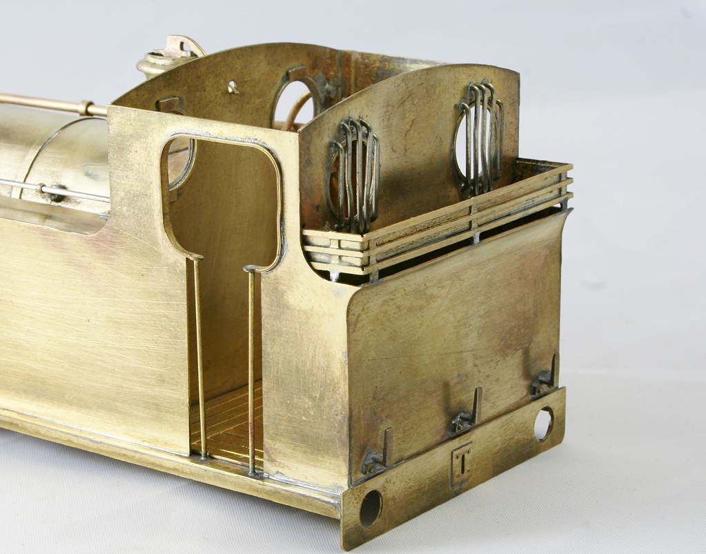
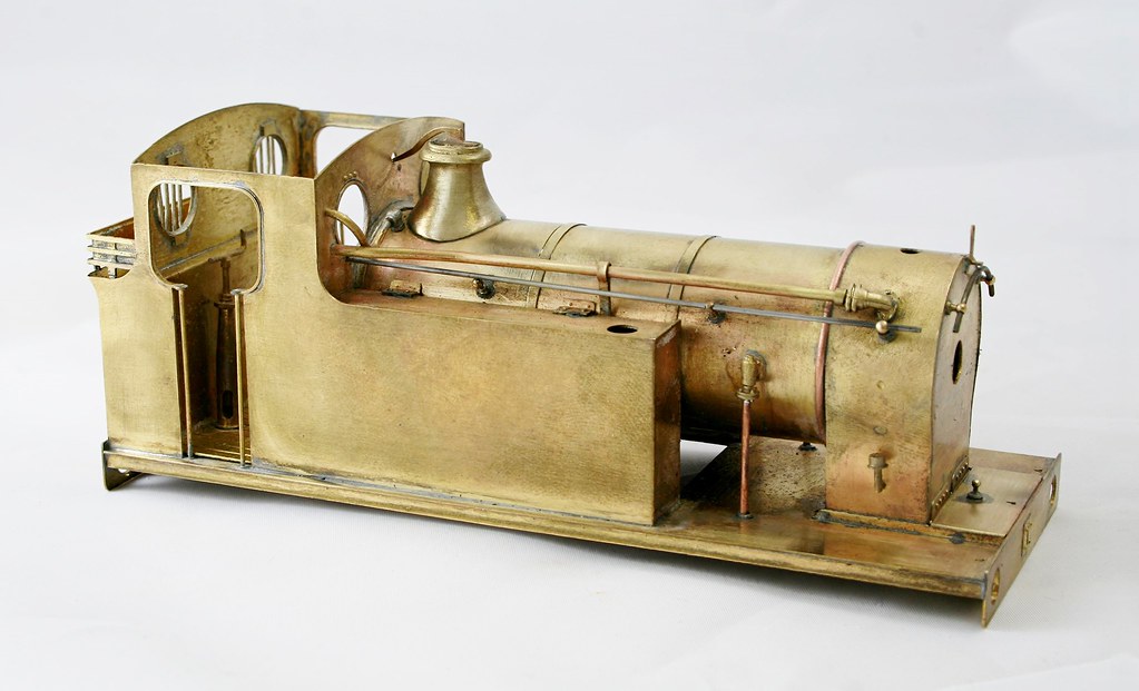
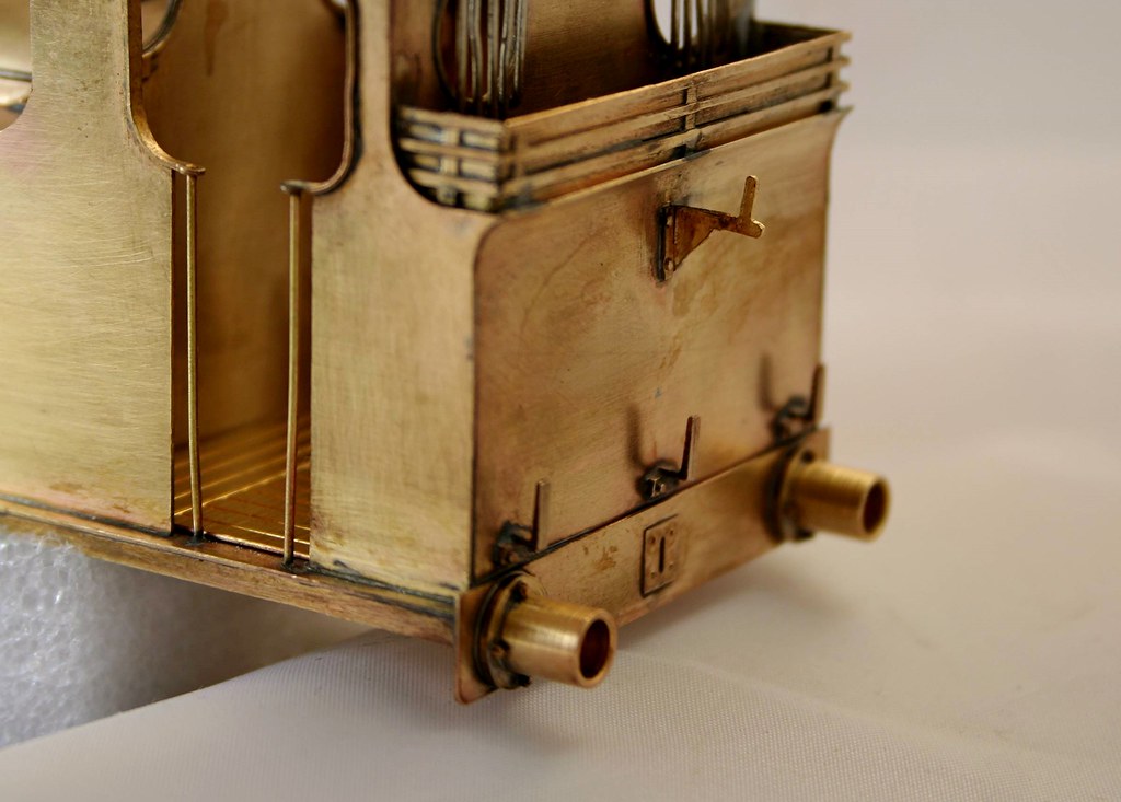
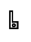
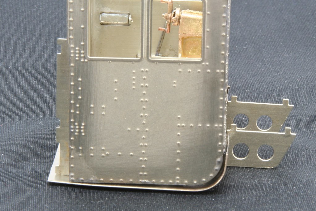
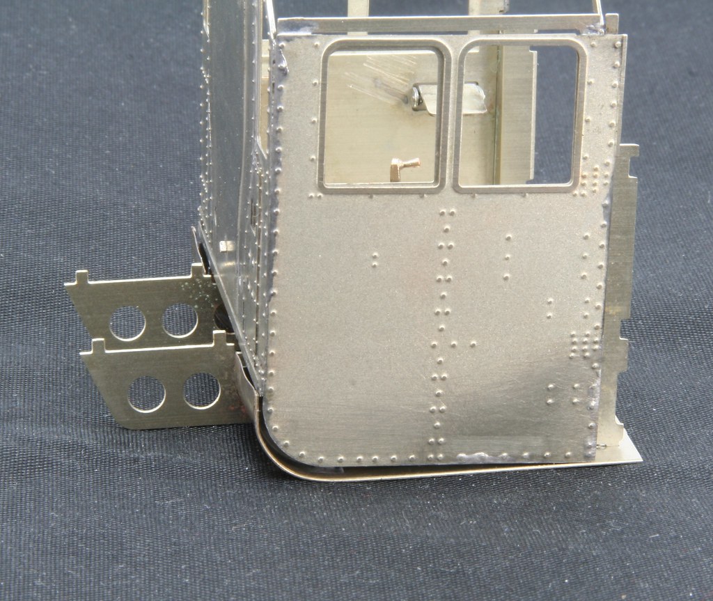
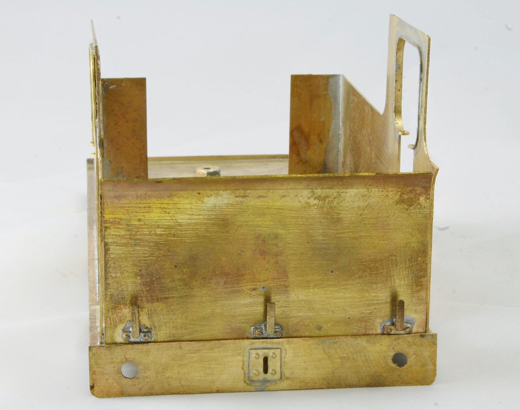
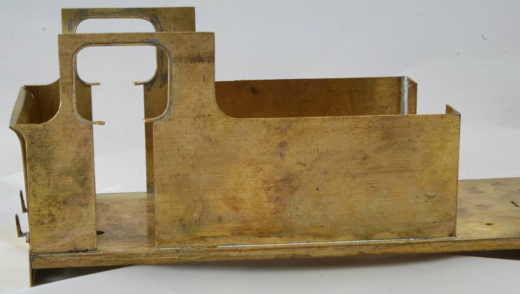
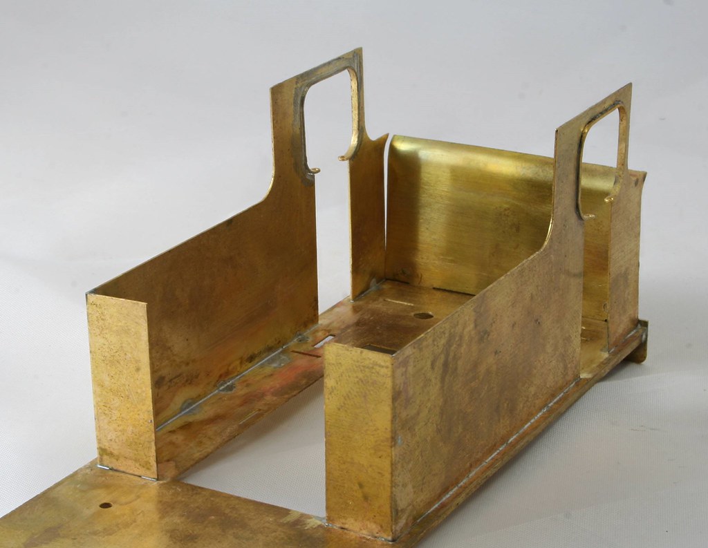
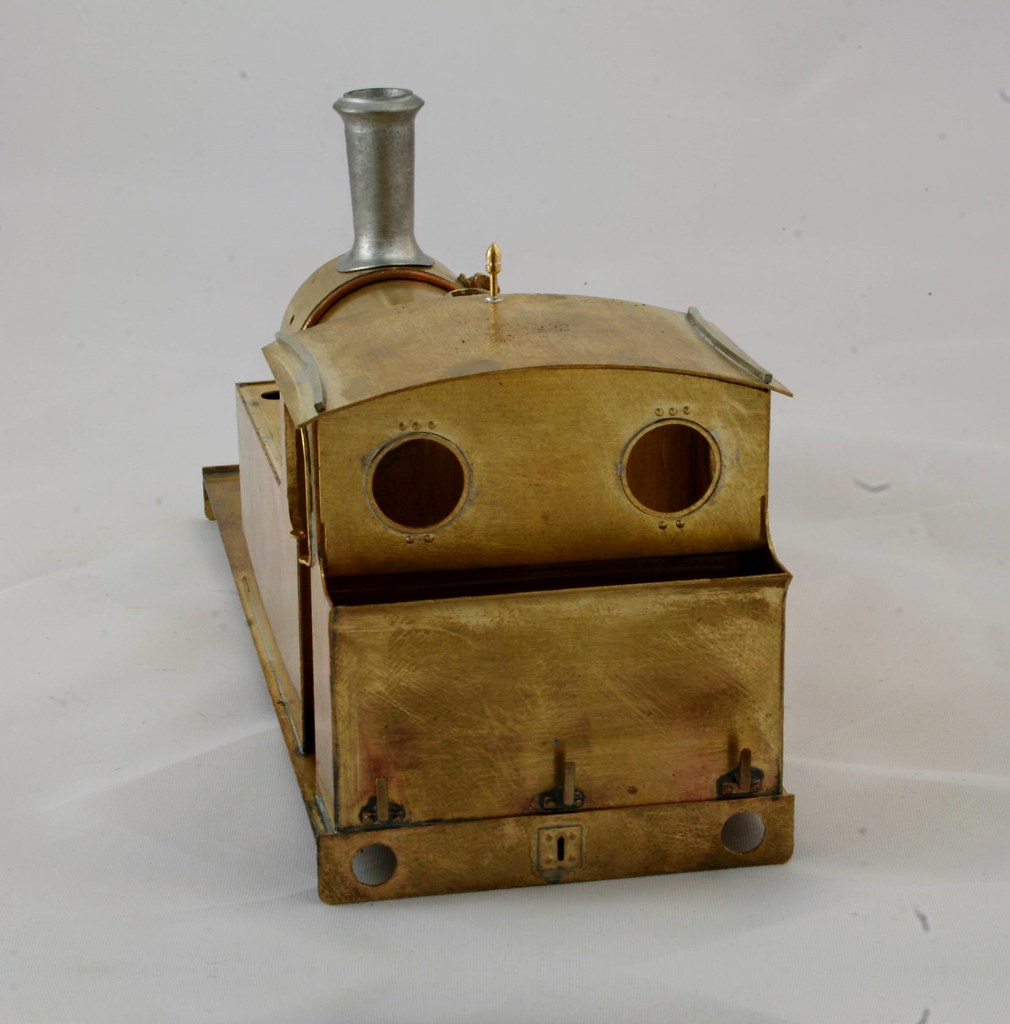
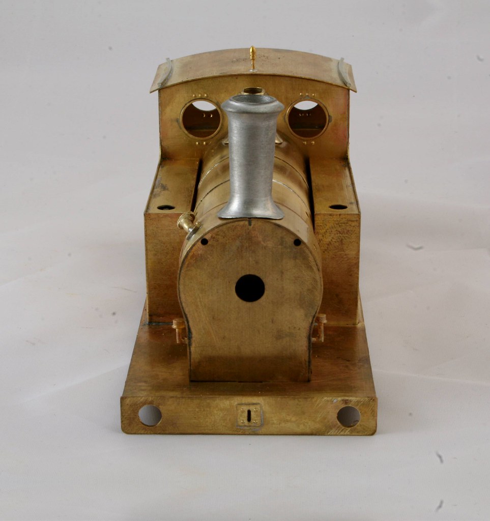
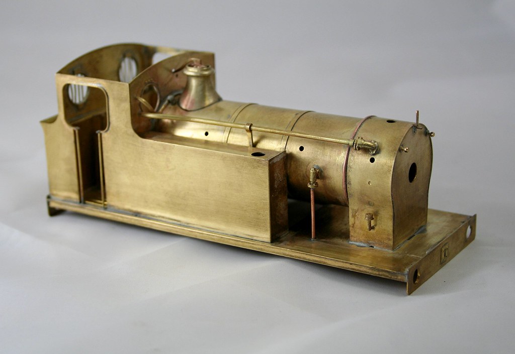
Work has progressed a little this week with me adding the cab beading and fitting the cab/bunker/tank sides to the footplate. I took a bit of care to make sure that I got the sides to the outer edge of the etched slots in the footplate - this is an older kit and some of the slots are slightly over etched.

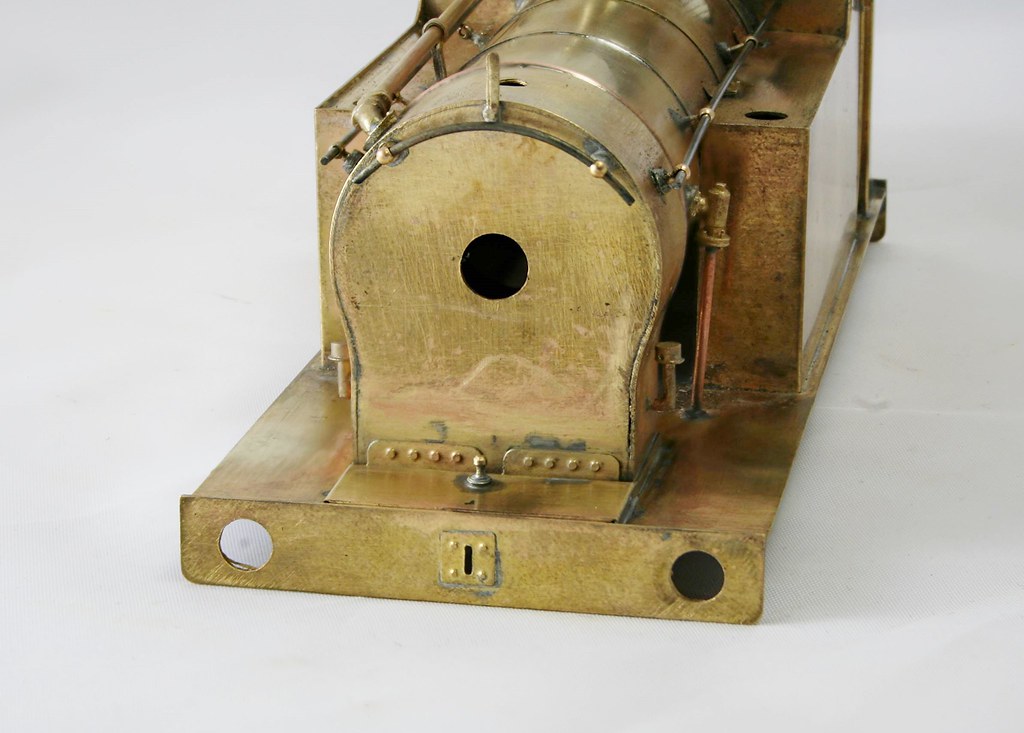
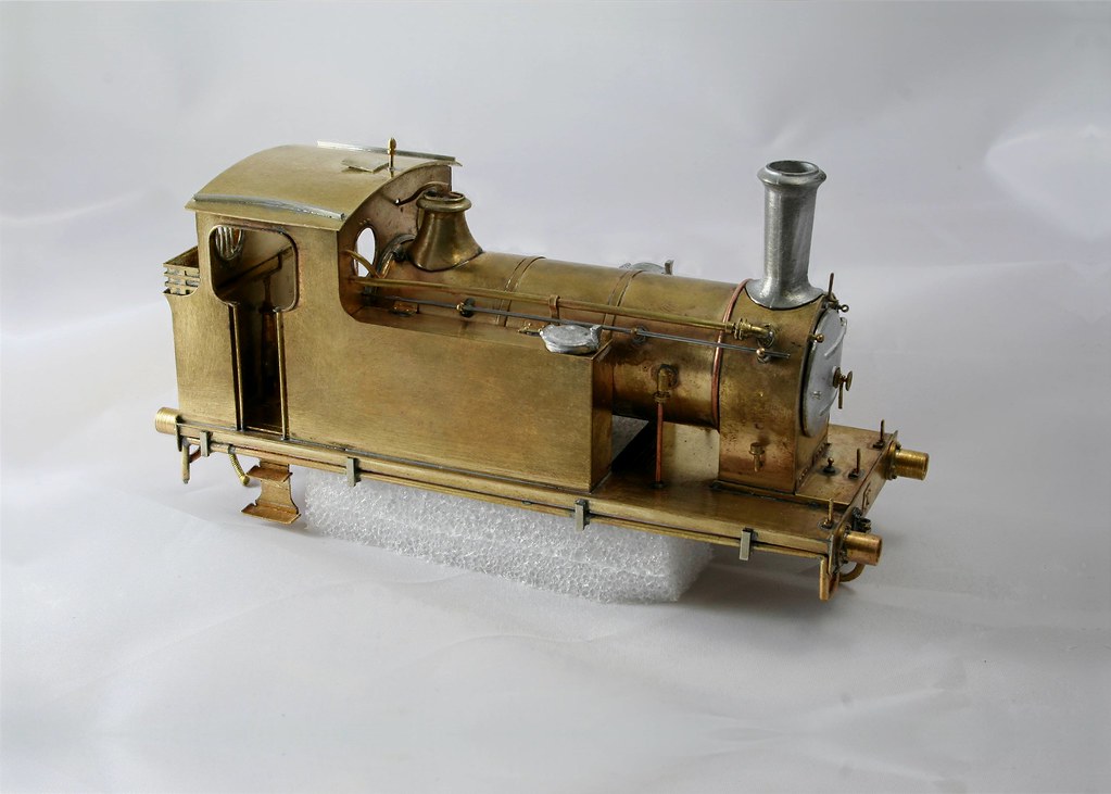
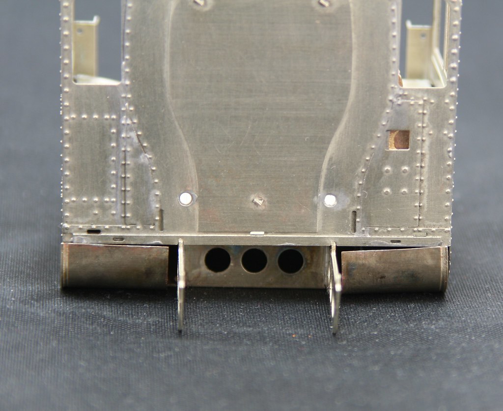
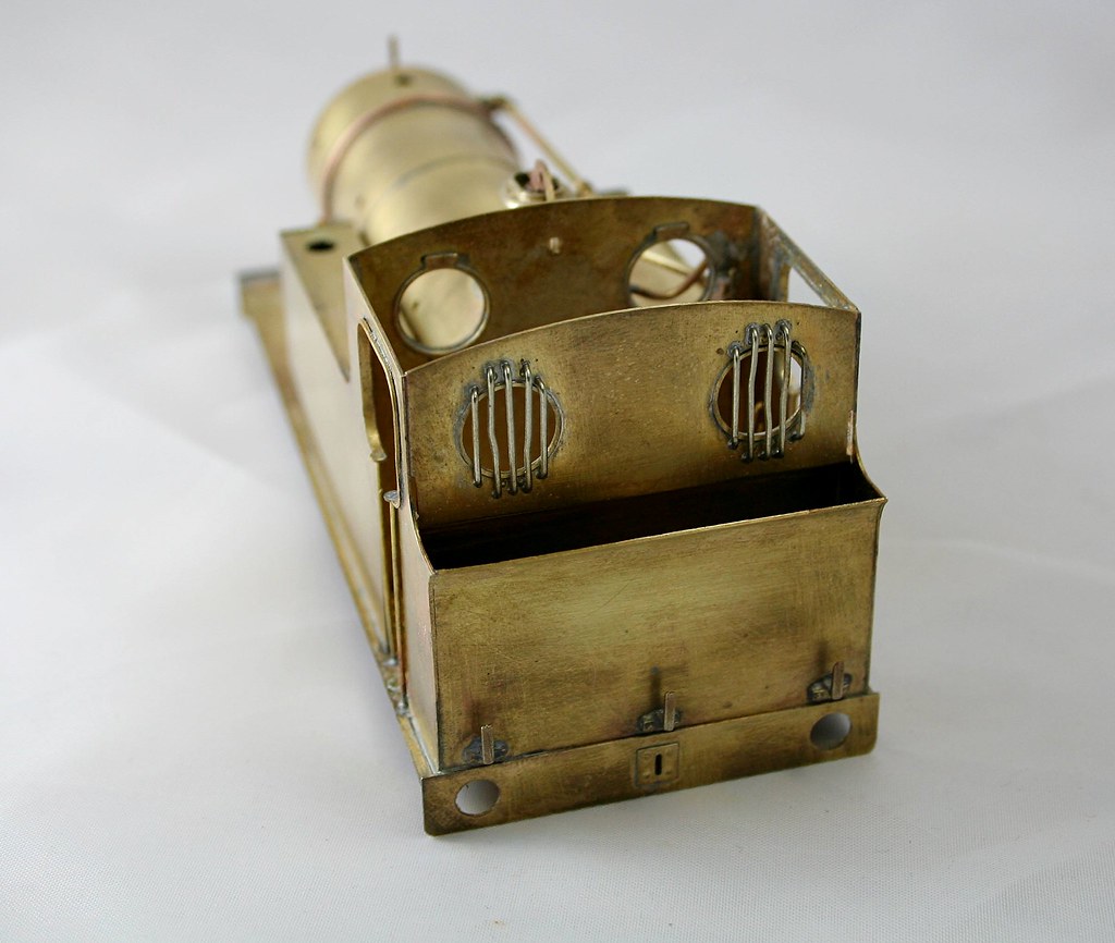
I then looked to fit the bunker rear and found that there is a slight gap at one side so I am probably going to have to adjust the left hand side as you view it from the rear. that may mean that I need to fill a small gap in the footplate top time will tell.

38111352712_750834b42a_b.jpg


38143136911_7d8859307a_b.jpg


37433708114_932a619c5c_b.jpg


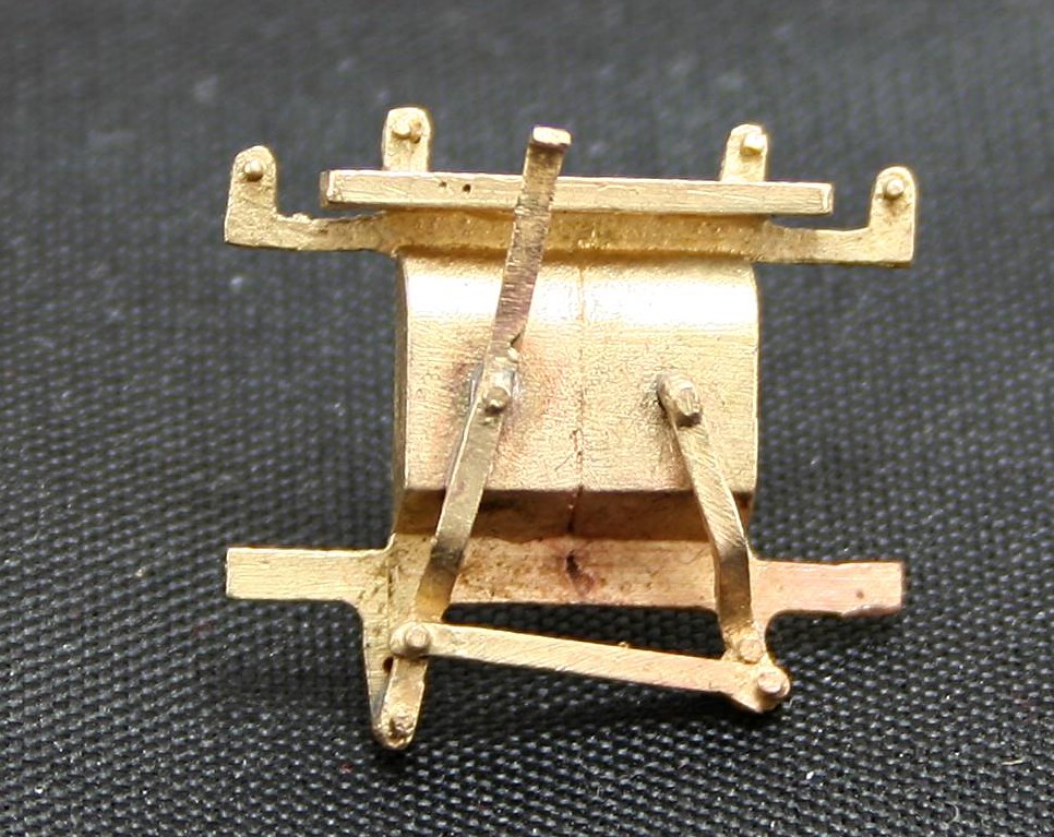
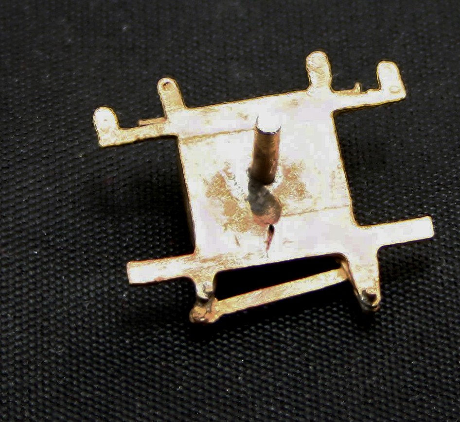
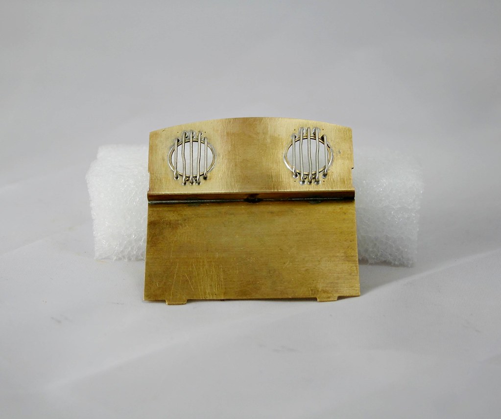
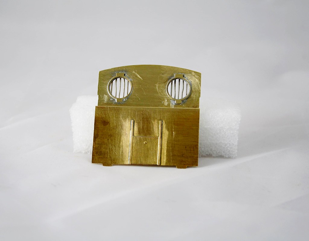
It was getting late by the time I discovered that so I moved onto something a little easier for my last 15 minutes or so. Namely the cab roof. I am quite impressed by Jim's design for this because it's usually a bit of a fiddle to get it to sit square and be retained in the cab. Jim's answer is a nifty fold up etch.

38143134521_cdd852747f_b.jpg


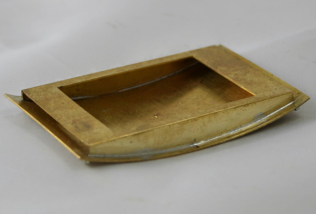
A note to anyone building one of these, there are half etched curves in the roof for locating the rain strips (the idea is that you solder in a length of thin wire and it becomes a half round rain strip). when rolling, the roof has a tendency to fold rather than roll smoothly. Backing it with a bit of card as it goes through the rollers would probably help with this.

Having none to hand I didn't bother, I just stopped passing it through the rollers right to the ends of the roof and effectively just rolled the middle section. I also replaced the wire with some small square section rod that I had in stock.

38111349572_afc1fbf183_b.jpg


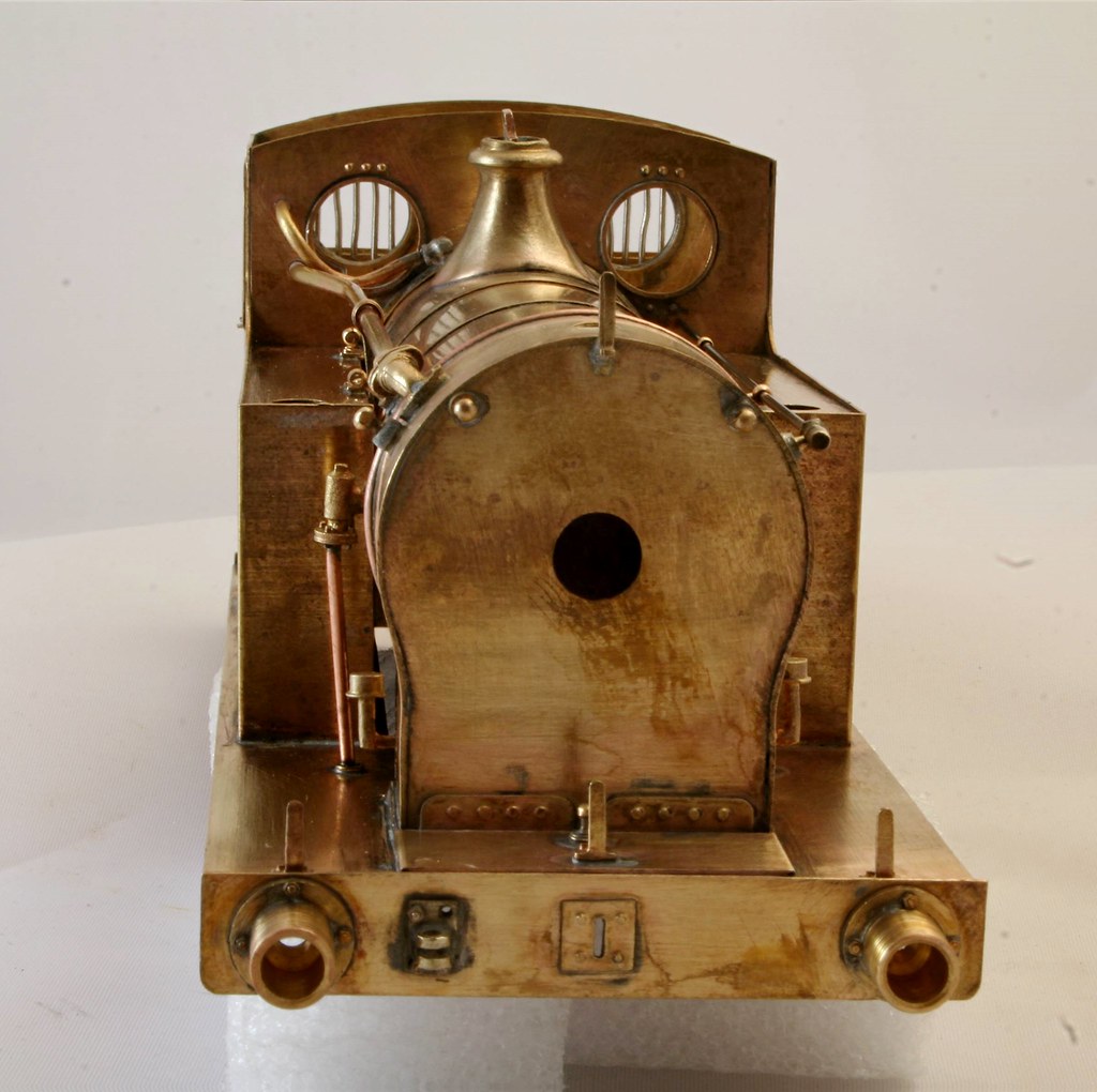
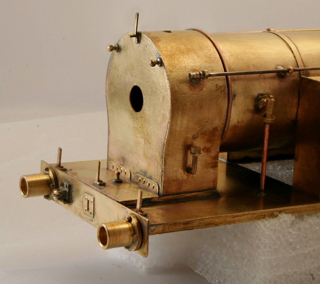
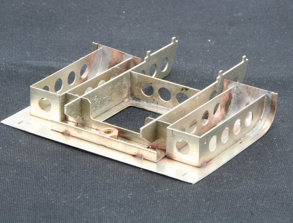
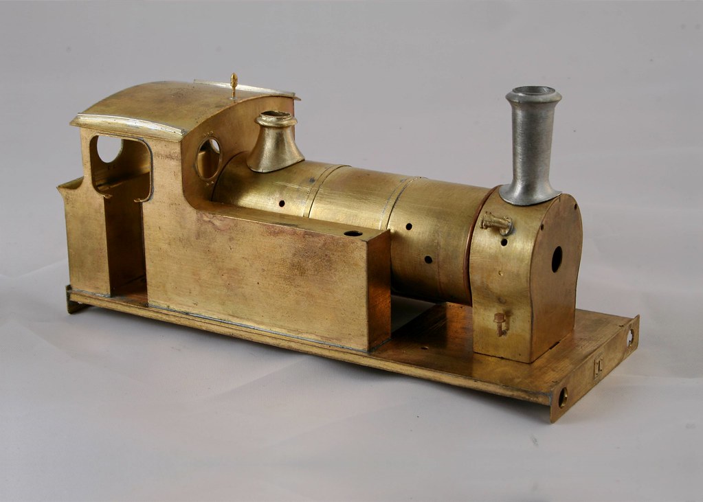
Lastly in true Blue Peter fashion, here's a bit that I did earlier. I had previously added the spacers and the boiler bands to the boiler but had popped it back in the kit box so missed taking any photos of it when I took the photos that I shared the other day.

38143135531_c8b6b87b5f_b.jpg


38111350262_7494c11ec3_b.jpg
 

Rob Pulham

Western Thunderer
A weekend at home has seen much progress on the J79.

The chimney and safety valve cover are just posed for the photo I want add more detail before fixing them in place.

24364691118_f588d0304d_b.jpg


38217345401_009fe0949d_b.jpg


The cab is still loose at this point too.

24364689228_9e7f63ed02_b.jpg


This is the reason that it's still loose, although at an oblique angle one of the photos that I have seems to show bars on over the rear windows which I have added - suitably distressed too.

38185424422_3540a2ed9a_b.jpg


24364687488_51f02abe94_b.jpg


Since taking this shot on Sunday morning I have made up the vacuum ejector pipe and soldered the rear of the cab in place.


38185422672_c97d3a6208_b.jpg


There is a lot going on for such a diminutive little loco
 

Rob Pulham

Western Thunderer
The last couple of evenings have seen more details added to the body of the J79

It now sports Clack valves, the safety valve bonnet, a front lamp iron on the smokebox and finally a connection and pipe to the tops of the firebox. I am not certain what this is exactly but noticed it on a recent photo posted by Mick Roffe of the preserved J72 too.

26491983309_02bc449c87_b.jpg


24397170608_784d6be3a4_b.jpg


26491982199_40c3959701_b.jpg


In the box were a nice pair of brass brake standards, one for the loco one for the spares box - the spares box has been heavily raided for this build.


24397169698_2b9ddb26b1_b.jpg


26491981119_48e82be602_b.jpg
 

Martin Shaw

Western Thunderer
Very nice looking Rob. The pipe from the cab to the smokebox is the vacuum ejector exhaust which is probably a post preservation addition to the J72. Whether the J79s ever had it I'm not certain, I'm somewhat too knackered to dig out a book tonight, but I'll have a look tomorrow.
Regards
Martin
 

FiftyFourA

Western Thunderer
As Martin says, it's the drain from the ejector which basically 'dumps' excess water that is part of the process of extracting air from the braking system to create the vacuum.

As for the J72, many were fitted by BR as they were used for empty stock working around the larger stations (Hull, Leeds, Newcastle, York on the old NER system) so would need a vacuum brake, however you would need to check very carefully about a J79.

There is a picture in NE Record Vol 3 pp 117 that shows H2 No 407 0n the Cawood, Wistow & Selby Light Railway vacuum fitted (so would have the vacumm drain fitted) but other pictures and drawings of the H2/J79 show only a loco brake. Best source is the RCTS green books if you know someone, 0r the appropriate Willie Yeadon.

Peter
 

Steph Dale

Western Thunderer
And, for completion, the pipe from the top of the firebox to the cab front is the steam for the brake ejector.
I've seen similar fittings on Adams LSWR locos that were retro-fitted with vac brake. Is that the case here?

At least you know where to fit the ejector in the cab!

Steph
 
Last edited:

Martin Shaw

Western Thunderer
Rob
Further to last nights post. Contrary to my comment the preserved J72 was vacuum fitted when built, and as Peter has commented many were retro fitted.
There were three J79s, two were built at Gateshead in 1897, nos 407 and 1787. They were airbraked, the pump being located in the cab, lucky crew. At some point 407 was rebuilt with larger tanks, possibly for work on the Cawood light railway. The third loco 1662 was built in 1907 and until 1930 was the Gateshead works shunter. It was then fitted with a vacuum ejector for the train only, the loco retaining its handbrake only.and transferred to Middlesborough shed in exchange for 1787. All three were withdrawn by 1937 and sold on for industrial use. (Info from RCTS vol 8B and Hoole).

Therefore Rob your model as it stands has to be of 1662 post 1930, remove the ejector exhaust and it could be 1787, 407 would need major work.

Regards
Martin

Edit. 407 and 1662 didn't have front foot steps, oddly 1787 did, possibly a later addition.
 
Last edited:

Rob Pulham

Western Thunderer
Thanks for the interest and looking details up for me Gents,

As Martin suggests it is to be 1662 post 1930 - I am working from photos in Yeadon vol 43B and I do have the RCTS books too - I just got the last two parts that I was missing for £2 each from the RCTS Stand at Spennymoor a couple of weeks ago.

The photo of it vacuum fitted in Yeadon does show the fitting on the top of the firebox I was just unsure what it actually did:oops:.
 

Rob Pulham

Western Thunderer
A session last night saw further details added to the body.

The coal rails were fitted and a plated infill added. My reading on the subject has revealed that they were plated over right from being built. Jim supplies them as open rails. A piece of scrap etch provided the infill.

26663274369_7cc154f33d_b.jpg


Handrails both sides were fitted but they needed bushing with a bit of tube over the base of the handrail knob to fill the slightly oversized holes - of course I then had to enlarge the holes again to get them to fit with the tube in place.

In the instructions (like many of his kits) Jim suggests the use of split pins instead of handrail knobs. For the J79, looking at the photos I have, it seems that handrail knobs are a better fit to the real thing than split pins would be.

26663277189_8d9bddc2f9_b.jpg


Finally the piano front was fitted after filing a piece of rod in the Dremel to make the quite visible knob for it.

26663270529_59b58ac1e5_b.jpg
 

Rob Pulham

Western Thunderer
As a bit of a distraction while painting other bit's and pieces, I primed and topcoated the Backhead. Over the weekend I picked out the details and added a bit of weathering.

Although I am not sure that the photos do the quality of Jim's little backhead for this loco, justice - what you see is all cast on the backhead with no additional pipework or castings. I was so impressed that I thought it would pass muster inside a closed cab without resorting to removing and re-adding details as I might have done with other backhead castings.

38488603606_2714b2b974_b.jpg


37828996184_8541276f04_b.jpg
 

Rob Pulham

Western Thunderer
Steady progress this week has seen more details added to the body.

The buffers all needed drilling out for the bolt heads - because I had them I used some of the rather nice Scale Hardware items

37713274325_c21b696e30_b.jpg


I also added the front lamp irons (Laurie Griffin castings) and the bracket on the front buffer plank which is visible in the photos that I have and Yeadon speculates that it was used for shunting locos/tenders when separated from each other. This was made from scrap nickel etch soldered together with 295 degree solder so it stayed together when I used 145 to add it to the buffer plank. - again a few more Scale Hardware items to finish it. - The eagle eyed amongst you will note that one went missing while washing it too...

37884198684_a3a60746ed_b.jpg


The hand rail on the fireman's side has a fitting that incorporates the support for the end of the handrail on the smokebox this was made up using some small bore tube, a disk of scrap etch and a 14BA nut. The tube sealed with the scrap etch was slid onto a stub of handrail protruding forward of the hand rail knob with the nut at the other side and all soldered in place. It's not strictly accurate but it will pas must once painted and is better than just a plain handrail knob.

37713273495_9bd0099cdb_b.jpg


It was discretely pointed out that the coal rails were plated right to the bottom and it for me it was a wood and trees moment because all my photos show it but it hadn't sunk in.

Remedying it involved taking the rails off again because try as I might I couldn't get the extra strip to stay in place while I soldered it while it was in situ.

The same discussion concluded that being vacuum fitted it probably had an upper rear lamp iron too. Scrap etch to the rescue. This was the second attempt because having made a lovely job of the first which was made from conveniently shaped bit of etch I realised that I had the slope rising up above the horizontal rather than below it as it should be.
 

Rob Pulham

Western Thunderer
A weekend at home in Wakefield for a family event has mean't extra time to crack on with the J71 which is almost there now.

Like most classes of locomotive, the J79's had a wealth of details over their life. a couple were Westinghouse fitted but 1662 was vacuum fitted in later life (it retained the steam brake for the loco braking) and the vacuum pipes were the under buffer plank hanging type rather than the more common upright variety.

The pipe rang down the bottom of the valance on the right had side of the engine and the mounting brackets looked quite substantial. Initially I made my usual mounts from scrap etch folded in 'P' shape but they just didn't look right. After a rummage in the box that I keep all my rod and strip sections in I came up at a loss and it wasn't until looking in a drawer for something else that I chanced upon some short lengths of bullhead rail.

They seemed perfect from an edge on view so a couple of attempts to get the right length later and I had 4 mounting brackets. To make them I drilled a hole through the web and then cut the from the back through the web like this

37956859564_0c773db3a1_m.jpg


24802069788_17c52b3438_b.jpg


I also drilled a hole in the roof and filed it square for the roof ventilator then cut a scrap of etch for the cover. To get it to sit at such a jaunty angle I popped a bit of thich scrap etch under it at one end then gripped the other with a pair of self locking tweezers. turn it over and touch the soldering iron inside the hole for the ventilator and its firmly held in place at an angle.


38618578366_e581091707_b.jpg


The remaining whitemetal body details were then fixed in place with epoxy and thoughts returned to the chassis.

24802068278_8f1509abcd_b.jpg


Not included in the kit but very visible on the sides of the chassis are a couple of injectors. A search through Laurie Griffins site didn't reveal any that looked remotely suitable so I decided to make my own from brass tube, rod and some 14BA nuts with copper wire for the pipes.

37956608214_6d18604c79_b.jpg


38618577266_6fd27378bd_b.jpg


And of course the photo has revealed that I need to nudge one of the nuts to close the gap...

Finally a shot with a 5p coin to show how big they aren't

37956607124_e636474960_b.jpg
 

Rob Pulham

Western Thunderer
A Happy New Year to all.

First a bit of a refresher, those with long memories can skip over this bit.

About 8 years ago my good lady became ill and had to give up work. She was fortunate in that she was able to take redundancy and she spent some her redundancy money on a kit for me. I chose the MOK 8F - MOK = Modern Outline Kits available from here MOK

I wanted the 8F to build as one of the locos that were ordered by the LNER during the war. My initial plan was to build one of the examples built by the Southern Railway for the LNER but further research since has changed that to become one of those built by the LNER at Darlington. You might ask why - because I wanted a riveted tender and I had already bought spoked wheels.

The ones built by the Southern had welded (smooth sided) tenders and most of the LNER built examples had solid wheels as on the tenders of the A3/4's but at least a couple of the Darlington examples had spoked wheels to go with the riveted tender. So mine will now be either 3135 or 3144

Rather embarrassingly I started it around 6 years or more ago and never got anywhere near finishing it. About 18 months ago I had a second bash but still didn't even get the tender finished. Chris has been pointedly asking most of this year when I am going to finish it and I had planned to return to it when I got distracted by the J79 in October. So I made the promise that I would return to it over Christmas and endeavour to get it completed.

I thought I would ease back into it with something easy, or so I thought. I started on detailing the backhead a week last Saturday.

These are some of the many parts that make it up.

39399254232_a60077b7c0_b.jpg


25559503828_893d0cb7ed_b.jpg


I had to make this up from a couple of pieces and I drilled and soldered a spigot to the back to make it easier to attach to the backhead itself.

39399253672_ff6d76f226_b.jpg


25559503358_edb997c164_b.jpg


Then the myriad of spaghetti that will be the pipework.

24563468667_cc1da7dc7a_b.jpg


Having seen Nick Dunhill's masterpiece a few weeks back I was keen to replicate the gauge glasses that he did. On this particular backhead this entailed cutting off the levers, and then cutting out the rectangle of brass to insert the square perspex later in the build and then reattaching the levers to the sides.

27657578459_11ccfa3f3b_b.jpg

38556735605_bf2c704b8c_b.jpg


These are the almost finished article that has taken just over a week to put together. - Most of the parts are removable to allow the backhead to be painted.

Because there are a few much better builds than mine on the forum I am not going to go into the level of detail that I might do normally but just show the key stages as I complete them - the main goal is to get it finished.
 

Rob Pulham

Western Thunderer
Now a plea for help and advice for those that have built this kit before. I have a bit of a problem and I am not sure if it's me that's done something wrong or it's a minor bip with the kit? - I am inclined to think the former given how well all the other parts fit.

24580297497_6921dc321b_b.jpg


24580297057_3a7b4a9793_b.jpg


39415960522_39aa073f09_b.jpg


24580296097_ecf8dd2f1c_b.jpg


From the photos you will see that the cab sub structure doesn't sit flat underneath the cab and when pressed and held in place the curved front doesn't match the profile of the cab sides leaving an unsightly gap. I can of course unsolder the base plate and file some of the curves of the frame but would prefer to understand what the problem is before I attempt to fix it.

Many thanks in advance for any insight you can offer.
 

Rob Pulham

Western Thunderer
Thanks Dave,

David's problem was slightly different in that he had his base plate on upside down.

Mine is the right way up but it still doesn't fit as well as I would expect and I would certainly agree with Dave Sharp that the instructions are pretty poor at this point...
 

markjj

Western Thunderer
The last batch of kits that I believe Dave issued came with these additional notes.
I'm sure he won't mind me sharing them here if it's any help.
One thing you need to do when rolling the edge of part 362 is to pack the half etched area with strong tape or tack card on with a glues that washes off or it will deform and go baggy at the front.

20180102_112921.jpg 20180102_112905.jpg
 
Top