You are using an out of date browser. It may not display this or other websites correctly.
You should upgrade or use an alternative browser.
You should upgrade or use an alternative browser.
The Low Quay Yard
- Thread starter Richard H
- Start date
Threadmarks
View all 20 threadmarks
Reader mode
Reader mode
Recent threadmarks
Underlay & second traverser Second traverser installed and working Cassettes, and keeping things on them Track laid at last - and a compromise accepted Electics and electronics DCC and other updates First two buildings Retiring from the competitionRichard H
Western Thunderer
Thanks, Paul - I turned off the lights in the workshop to enhance the effect of the LEDs and took a photo 'for the record', then realised that the photo itself was quite dramatic - I just rather liked it and thought it worth sharing.Wow Richard, that's impressive.
Fiddle yards and control desk progress
Richard H
Western Thunderer
The Squire of Old Parrock suggested a progress report so, with a duly obeisant tug of the forelock, here are some photographs of my recent activities.
I have been working on the two fiddle yard boards (right hand one a nominal 500mm long, and the left one 450mm) and a dismountable control 'desk'. Each fiddle yard has a drawer-like box under the running surface, sitting between the extendable drawer runners. These boxes are intended to hold dismountable structures and stock during transit. The fiddle yards incorporate softwood bearers that locate directly onto the drawer runners, and the boards are then locked into place against the main baseboard using single-hand operating ratchet clamps.
The first photograph shows the basic box / drawer structure of the fiddle yard boards. This is the right-hand one (looking at the front of the layout); the floor of the well that carries the short cassettes has not yet been fitted. At the front corner it is possible to see the channel which sits over the extendable drawer runners.

The next photograph shows the base of the well in place, supporting a temporary cassette. I shall contrive a very simple locating system for cassettes. The track at the rear of the board will be a fixed track, a simple extension of a siding on the main board.
![Fiddle yard Well with fixed siding [rear] and temp cassette [front] 171205.JPG](https://www.westernthunder.co.uk/attachments/fiddle-yard-well-with-fixed-siding-rear-and-temp-cassette-front-171205-jpg.82243/ "Fiddle yard Well with fixed siding [rear] and temp cassette [front] 171205.JPG")
The third photograph shows this fiddle yard board inverted to reveal the hole in the bottom of the drawer (on the centre line) which is used for clamping this boards to the main board. The clamps are simply one-hand ratchet clamps, size 50mm, bought from Wickes (fourth photograph).
![Clamping hole in base of RH fiddle yard [board inverted in photo] 171207 copy for forum.JPG](https://www.westernthunder.co.uk/attachments/clamping-hole-in-base-of-rh-fiddle-yard-board-inverted-in-photo-171207-copy-for-forum-jpg.82244/ "Clamping hole in base of RH fiddle yard [board inverted in photo] 171207 copy for forum.JPG")

The boards are contructed by glueing the ply, and this requires some fairly careful clamping to hold everything in place while the glue sets. In this sense "careful" means using set squares to align components, then lots of (cheap) clamps, with improvisation as necessary. The next photograph shows the left-hand fiddle yard clamped up in situ to make sure that everything locates accurately, with a spacer bar to keep the laterally unsupported drawer bearers the right distance apart at the outer 'open' end. You can just see, wedged between the fiddle yard and the main board, a strip of thin polythene with a black squirly pattern (cut from a carrier bag) placed as a mask to prevent parts sticking together where this is not wanted. Careful masking is absolutely necessary when glueing in situ, to avoid unintentionally ending up with a permanently and depressingly integrated structure.

The sixth photograph shows the "control desk"; this rather pretentious name translates as "box holding the controls for my train set", but it is a separate unit and so needed its own name. It is designed to sit on top of the right-hand fiddle yard in use and to be stored inside it for transit (the layout will be operated from the front both at home and if ever at an exhibition).
The layout will be operated using a Gaugemaster Prodigy Advance for train control, and DCCconcepts Cobalt Alpha electronics for points and accessory control using a mimic panel with a schematic diagram. The control desk accommodates the Gaugemaster and three Alpha components - the LED switches interface, the digital encoder, and the Adaptor / "Sniffer" unit. The irregular shape of the control desk is a result of "form following function". The control desk also acts as a partial screen for the fiddle yard. The schematic diagram seen in the photograph is a mock-up.

The dismountable control desk will connect to the layout wiring with loose cables. This method also allows for the same control equipment to be used on different layouts. The schematic mimic panel and the small shelf holding the handset both lift out to allow clear access to the electronics for programming, etc. and the schematic switch panel could easily be replaced with one for another layout. In use the whole unit is held in place with short removable dowels.
Clearly, there is still finishing work to do on the baseboards; I also need to construct a screen / information board for the left-hand fiddle yard, and fit LED lights to the lighting gantry. I now know that the main layout structure is viable, though, and should provide a good foundation for tracklaying, DCC and actual modelling (which are, of course, the scarier parts of the project).
Happy Christmas, and best wishes for 2018!
Richard
I have been working on the two fiddle yard boards (right hand one a nominal 500mm long, and the left one 450mm) and a dismountable control 'desk'. Each fiddle yard has a drawer-like box under the running surface, sitting between the extendable drawer runners. These boxes are intended to hold dismountable structures and stock during transit. The fiddle yards incorporate softwood bearers that locate directly onto the drawer runners, and the boards are then locked into place against the main baseboard using single-hand operating ratchet clamps.
The first photograph shows the basic box / drawer structure of the fiddle yard boards. This is the right-hand one (looking at the front of the layout); the floor of the well that carries the short cassettes has not yet been fitted. At the front corner it is possible to see the channel which sits over the extendable drawer runners.
The next photograph shows the base of the well in place, supporting a temporary cassette. I shall contrive a very simple locating system for cassettes. The track at the rear of the board will be a fixed track, a simple extension of a siding on the main board.
The third photograph shows this fiddle yard board inverted to reveal the hole in the bottom of the drawer (on the centre line) which is used for clamping this boards to the main board. The clamps are simply one-hand ratchet clamps, size 50mm, bought from Wickes (fourth photograph).
The boards are contructed by glueing the ply, and this requires some fairly careful clamping to hold everything in place while the glue sets. In this sense "careful" means using set squares to align components, then lots of (cheap) clamps, with improvisation as necessary. The next photograph shows the left-hand fiddle yard clamped up in situ to make sure that everything locates accurately, with a spacer bar to keep the laterally unsupported drawer bearers the right distance apart at the outer 'open' end. You can just see, wedged between the fiddle yard and the main board, a strip of thin polythene with a black squirly pattern (cut from a carrier bag) placed as a mask to prevent parts sticking together where this is not wanted. Careful masking is absolutely necessary when glueing in situ, to avoid unintentionally ending up with a permanently and depressingly integrated structure.
The sixth photograph shows the "control desk"; this rather pretentious name translates as "box holding the controls for my train set", but it is a separate unit and so needed its own name. It is designed to sit on top of the right-hand fiddle yard in use and to be stored inside it for transit (the layout will be operated from the front both at home and if ever at an exhibition).
The layout will be operated using a Gaugemaster Prodigy Advance for train control, and DCCconcepts Cobalt Alpha electronics for points and accessory control using a mimic panel with a schematic diagram. The control desk accommodates the Gaugemaster and three Alpha components - the LED switches interface, the digital encoder, and the Adaptor / "Sniffer" unit. The irregular shape of the control desk is a result of "form following function". The control desk also acts as a partial screen for the fiddle yard. The schematic diagram seen in the photograph is a mock-up.
The dismountable control desk will connect to the layout wiring with loose cables. This method also allows for the same control equipment to be used on different layouts. The schematic mimic panel and the small shelf holding the handset both lift out to allow clear access to the electronics for programming, etc. and the schematic switch panel could easily be replaced with one for another layout. In use the whole unit is held in place with short removable dowels.
Clearly, there is still finishing work to do on the baseboards; I also need to construct a screen / information board for the left-hand fiddle yard, and fit LED lights to the lighting gantry. I now know that the main layout structure is viable, though, and should provide a good foundation for tracklaying, DCC and actual modelling (which are, of course, the scarier parts of the project).
Happy Christmas, and best wishes for 2018!
Richard
Richard H
Western Thunderer
Hi Mick,Richard,
Excellent work - nice, simple philosophy - very neat and tidy too.
Mick S.
Thank you - I've been following your work on Callerton with some sense of awe, so I value what you've written. I have to confess that the simple philosophy is in part because I'm not at all confident of my ability to work out a sophisticated one!
Richard
Überclamping
Richard H
Western Thunderer
When I worked with Paul, the Squire of Old Parrock, to design and build our main baseboards, we divided the remaining ply between us to use on fiddle yards, etc. My share of the stock is now virtually exhausted and I've reached the stage where I'm trimming offcuts of offcuts to make usable parts. Today I worked on a box structure and had to use said offcuts, one of which was a strip of ply that I'd previously avoided because it was bent. In glueing up the basic box, I had to devise a method I can only call Überclamping. Essentially I had to hold everything in alignment but at the same time hold the front and rear longitudinal pieces so that they were straight.
I took a photograph illustrating the essence of Überclamping - holding a simple box together on its base (a 450 x 22mm footprint) required six clamping blocks fitted into the jaws of a workbench, along with a total of eight other clamps of different sorts.

The silly thing about this effort is that the box is to some extent an experiment, and I'm not entirely sure that my projected use for it will actually work. I'm beginning to whether if I should have taken up Lego modelling.
Richard
I took a photograph illustrating the essence of Überclamping - holding a simple box together on its base (a 450 x 22mm footprint) required six clamping blocks fitted into the jaws of a workbench, along with a total of eight other clamps of different sorts.
The silly thing about this effort is that the box is to some extent an experiment, and I'm not entirely sure that my projected use for it will actually work. I'm beginning to whether if I should have taken up Lego modelling.
Richard
Richard H
Western Thunderer
When I worked with Paul, the Squire of Old Parrock, to design and build our main baseboards, we divided the remaining ply between us to use on fiddle yards, etc. My share of the stock is now virtually exhausted and I've reached the stage where I'm trimming offcuts of offcuts to make usable parts. Today I worked on a box structure and had to use said offcuts, one of which was a strip of ply that I'd previously avoided because it was bent. In glueing up the basic box, I had to devise a method I can only call Überclamping. Essentially I had to hold everything in alignment but at the same time hold the front and rear longitudinal pieces so that they were straight.
I took a photograph illustrating the essence of Überclamping - holding a simple box together on its base (a 450 x 22mm footprint) required six clamping blocks fitted into the jaws of a workbench, along with a total of eight other clamps of different sorts.
View attachment 82299
The silly thing about this effort is that the box is to some extent an experiment, and I'm not entirely sure that my projected use for it will actually work. I'm beginning to whether if I should have taken up Lego modelling.
Richard
...and now, the alternative method for fairly well-fitting but awkwardly shaped components - Unter-clamping!
I could keep my Lego in this box!
mickoo
Western Thunderer
Fill it quick before Steve parks his Millenium Falcon in there...and now, the alternative method for fairly well-fitting but awkwardly shaped components - Unter-clamping!
View attachment 82344
I could keep my Lego in this box!

Like others have said, nice clean work and I like the original scope and detail you laid our that drives the project.
MD
Richard H
Western Thunderer
Thank you - that's encouraging. I think I may be able to focus on the railway itself soon, and Lego of the distractions,Fill it quick before Steve parks his Millenium Falcon in there
Like others have said, nice clean work and I like the original scope and detail you laid our that drives the project.
MD
Richard
Oops - lack of forethought
Richard H
Western Thunderer
I had to reconstruct something today, when I realised that the box I'd made to support the screen on one of the fiddle yards was too high to fit inside the storage 'drawer' for transit. Oops! Very Oops! The first viable option was to trim the top of the box to fit. Cutting a slice off the top of an already constructed box of slightly irregular shape (it has a raked front panel) was a mildly interesting challenge, but the photograph shows the result:

The necessary adjustments are now finished with the results that (a) the box is now reconstructed for use in supporting a fiddle yard screen, and (b) it fits inside the fiddle yard storage drawer to provide storage in transit. Moral of story; measure twice and cut once ... but think hard before deciding what to measure!
The necessary adjustments are now finished with the results that (a) the box is now reconstructed for use in supporting a fiddle yard screen, and (b) it fits inside the fiddle yard storage drawer to provide storage in transit. Moral of story; measure twice and cut once ... but think hard before deciding what to measure!
Main components of baseboards constructed
Richard H
Western Thunderer
Today I was able to put all the various sub-assemblies of my baseboards together for the first time. Some of the components still need paint, but the photographs below show how they fit together. I have (admittedly rather roughly) edited the backgrounds out of the photographs so that the baseboard structure is apparent.


Built primarily for home use, the layout and both fiddle yards will be operated from the front. The screens are intended for use should the layout ever be exhibited. Despite the unfinished paintwork, I feel that I have a viable baseboard system (scenic board, fiddleyards at each end, screens doubling as display/information panels, integral storage, lighting gantry and control desk), and that this represents my second milestone.
All I have to do now is build a railway on it.
Richard.
Lyndhurstman
Western Thunderer
All I have to do now is build a railway on it.
Richard.
Lovely. I’d be staring at it for hours just as it is (does that make me weird? ). I’m sure there’s a Turner Prize with your name on it.
Cheers
Jan
Richard H
Western Thunderer
Thank you, Jan, for your kind comment. I did actually enjoy taking the pictures to try to emphasise its features, and seeing it together as a whole for the first time was quite instructive ... and I did indeed spend some time today just looking at it, while reflecting on the next stages.Lovely. I’d be staring at it for hours just as it is (does that make me weird? ). I’m sure there’s a Turner Prize with your name on it.
Cheers
Jan
Richard
Chris Veitch
Western Thunderer
I've only skimmed it so far but it looks to be a great little back story for a very interesting project - made more so for me as my office overlooks the southern Shields Ferry landing.
Your woodwork is incredibly precise - are you cutting the ply by hand or using a router?
Your woodwork is incredibly precise - are you cutting the ply by hand or using a router?
Richard H
Western Thunderer
Hello Chris,
Thanks for your comments. The back story emerged from historical research about North Shields and the Low Lights which I have been undertaking in another (non-railway) context; I enjoyed using some of the findings about the industries of the quayside area in developing a whimsical justification of my cameo layout.
I didn't use a router at all for the woodwork. I bought the 6mm birch-faced ply from a local timber merchant and had them cut the 8'x4' sheets into four manageable pieces for transport, the cuts being carefully worked out to accommodate key baseboard dimensions and yet keep as many options open as possible. Paul (the Squire of Old Parrock) and I then cut the sheet ply as necessary, either using a bandsaw (an amateur model sold by Axminster, but fitted with one of their decent blades), or a handsaw when the workpiece was too large to pass through the throat of the saw. Rounded corners were usually cut using a hole-cutter. When cutting sheets by hand I made sure that the workpiece was securely held and well supported to allow accurate cutting. I'd invested in three folding workbenches last year when they were on offer at about £9 each (I think Lidl, but perhaps Aldi), and these proved invaluable for supporting sheets for cutting. I used a 10 teeth/inch panel saw for sheets and a 14 teeth/inch tenon saw for smaller cuts. Circular and round-topped holes were made using a hole-cutter in a battery-powered hand-drill, and then where necessary I cut the straight sides of the aperture using an old Eclipse padsaw. I also used a coping saw for some small or awkward shapes, such as the aperture for the mimic panel in the control desk. The cut holes were cleaned up using a sharp chisel, a rasp or coarse cutting file, and emery paper wrapped round a convenient former.
The advantage I found about using the bandsaw is that it is possible to get great consistency, which I find is sometimes more useful than absolute dimensional accuracy. Your comment about my work being precise is kind, but I must confess that occasional cumulative inaccuracies have crept in, and that the paint hides the odd goof.
Just for interest and as an antidote to "too much information", here's an abstract from the 1st Edition OS Town Plan (c. early 1860s) which shows a rail-served quay in South Shields, a real-life micro-layout. It lay further east than the Ferry Landing, nearer the mouth of the river, and north of where St Stephen's Church is (and almost directly opposite North Shields Fish Quay); I haven't traced the rail connection - it may have been just an internal industrial system.

Cheers,
Richard
Thanks for your comments. The back story emerged from historical research about North Shields and the Low Lights which I have been undertaking in another (non-railway) context; I enjoyed using some of the findings about the industries of the quayside area in developing a whimsical justification of my cameo layout.
I didn't use a router at all for the woodwork. I bought the 6mm birch-faced ply from a local timber merchant and had them cut the 8'x4' sheets into four manageable pieces for transport, the cuts being carefully worked out to accommodate key baseboard dimensions and yet keep as many options open as possible. Paul (the Squire of Old Parrock) and I then cut the sheet ply as necessary, either using a bandsaw (an amateur model sold by Axminster, but fitted with one of their decent blades), or a handsaw when the workpiece was too large to pass through the throat of the saw. Rounded corners were usually cut using a hole-cutter. When cutting sheets by hand I made sure that the workpiece was securely held and well supported to allow accurate cutting. I'd invested in three folding workbenches last year when they were on offer at about £9 each (I think Lidl, but perhaps Aldi), and these proved invaluable for supporting sheets for cutting. I used a 10 teeth/inch panel saw for sheets and a 14 teeth/inch tenon saw for smaller cuts. Circular and round-topped holes were made using a hole-cutter in a battery-powered hand-drill, and then where necessary I cut the straight sides of the aperture using an old Eclipse padsaw. I also used a coping saw for some small or awkward shapes, such as the aperture for the mimic panel in the control desk. The cut holes were cleaned up using a sharp chisel, a rasp or coarse cutting file, and emery paper wrapped round a convenient former.
The advantage I found about using the bandsaw is that it is possible to get great consistency, which I find is sometimes more useful than absolute dimensional accuracy. Your comment about my work being precise is kind, but I must confess that occasional cumulative inaccuracies have crept in, and that the paint hides the odd goof.
Just for interest and as an antidote to "too much information", here's an abstract from the 1st Edition OS Town Plan (c. early 1860s) which shows a rail-served quay in South Shields, a real-life micro-layout. It lay further east than the Ferry Landing, nearer the mouth of the river, and north of where St Stephen's Church is (and almost directly opposite North Shields Fish Quay); I haven't traced the rail connection - it may have been just an internal industrial system.
Cheers,
Richard
Last edited:
Chris Veitch
Western Thunderer
Thanks for that Richard - I'd never thought of a bandsaw but it now seems like a useful choice. Fortunately I don't have room to accommodate one and fiddle unproductively with it - I can sympathise with the comment at the beginning of your first post about never finishing anything. I'm congenitally incapable of finishing stuff and for this reason I'm trying a 2FS cameo-type layout/test track, simply with the intention of actually doing something useful rather than entering the competition.
There are a fascinating selection of railway bits and pieces around the north east for obvious reasons but I'll admit I'd never heard of the one you mention in South Shields - it seems from Rail Map Online and this page from TW archives that it was used for removing and dumping ships' ballast somewhere around where the current Marine Park is, via a tunnel under the east side of the town. Oddly the Industrial Railway Society's very comprehensive Industrial Railways and Locomotives of County Durham doesn't mention it, but South Tyneside archives has a whole page of their site covering photos of the ballast hills created by this activity.
There are a fascinating selection of railway bits and pieces around the north east for obvious reasons but I'll admit I'd never heard of the one you mention in South Shields - it seems from Rail Map Online and this page from TW archives that it was used for removing and dumping ships' ballast somewhere around where the current Marine Park is, via a tunnel under the east side of the town. Oddly the Industrial Railway Society's very comprehensive Industrial Railways and Locomotives of County Durham doesn't mention it, but South Tyneside archives has a whole page of their site covering photos of the ballast hills created by this activity.
Richard H
Western Thunderer
Thanks very much for the links, Chris - I'm delighted to know more about this site. It hadn't occurred to me that it might be a ballast quay; your links set me searching too, and I found this link which has a scrolling text panel that includes some quite specific history about Salmon's Quay and its associated railway: South Tyneside Historic Images Online
I take no credit for discovering the joys and benefits of the bandsaw. A couple of years ago a friend who makes musical instruments told me, in the sort of tones that Albus Dumbledore might use when admonishing a young wizard, "... but you must get a bandsaw!". I followed his advice, and it took me about three days to realise that he was absolutely right.
Thanks again! (I must not get distracted; I must not get distracted; I must not ... )
Last edited:
Chris Veitch
Western Thunderer
At the risk of hijacking your thread with my own SBB, I've had a hankering after a 19th Century north-eastern harbour scene for years and your own project just hits the spot (although a little later in its time period). There are many inspirational photos around but these are two that have stuck with me - admittedly one's not a harbour scene but has a quirky north-easterness all of its own.
This is a ballast quay with narrow gauge waggonway on the north bank of the Wear - I really like the tumbledown buildings and randomness of the whole scene and have mulled over a NG scene for years based on this. I'd guess the building styles in North Shields would be no different at that time.
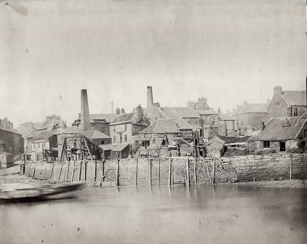 North Ferry Point, Monkwearmouth, 1879 by Sunderland Museum, on Flickr
I've no idea of the attribution of this one so can't credit it - it hangs on the wall of a pub in Gateshead and I've asked Beamish about it, but it's not know to them or in any of their collections which cover much of the colliery histories. It shows a splendid selection of stock lettered for the Earl of Durham's colliery railway but I don't know the location. There's something attractive and modellable about the outside framed, inside bearing stock and the small scale mine buildings.

This is a ballast quay with narrow gauge waggonway on the north bank of the Wear - I really like the tumbledown buildings and randomness of the whole scene and have mulled over a NG scene for years based on this. I'd guess the building styles in North Shields would be no different at that time.
North Ferry Point, Monkwearmouth, 1879 by Sunderland Museum, on FlickrI've no idea of the attribution of this one so can't credit it - it hangs on the wall of a pub in Gateshead and I've asked Beamish about it, but it's not know to them or in any of their collections which cover much of the colliery histories. It shows a splendid selection of stock lettered for the Earl of Durham's colliery railway but I don't know the location. There's something attractive and modellable about the outside framed, inside bearing stock and the small scale mine buildings.
Dog Star
Western Thunderer
Very nice material.... I've had a hankering after a 19th Century north-eastern harbour scene for years ...
This is a ballast quay with narrow gauge waggonway on the north bank of the Wear...
There is a WT-er, @Archie Atkinson, who is thought to be considering something similar albeit for Tynecastle.
Threadmarks
View all 20 threadmarks
Reader mode
Reader mode