A first kit-build: 3500 Gallon Churchward Tender - 4mm Scale.

oldravendale

Western Thunderer
The convention is to bend with the half etched lines on the inside. Normally, if the half etched line is to go on the outside this is specifically mentioned in the instructions.

As for forming the the front of the tanks I can see - I think - how that should be done but I'm not sure I could explain it any better, and I've not actually built the kit either! I'll leave that to someone who has a better understanding.

Brian
 

jonte

Western Thunderer
The convention is to bend with the half etched lines on the inside. Normally, if the half etched line is to go on the outside this is specifically mentioned in the instructions.

As for forming the the front of the tanks I can see - I think - how that should be done but I'm not sure I could explain it any better, and I've not actually built the kit either! I'll leave that to someone who has a better understanding.

Brian

Thank goodness, Brian. There’s no specific mention of bending to the outside so it’s as I thought.

No probs, but thanks for getting in touch and grateful for the prompt reply.

Jonte

Edit: Just studied it again, and I THINK I now see what it means - When the 90* bends are formed, the extensions with the diagonal bits on wrap around the ‘peninsulas’ on both sides, and the diagonal bits themselves form the sides of the peninsulas when the bit in the middle is bent downwards. They are then soldered where they meet the ends and side of these peninsulas which are on the ‘top’ of the tank former. Jonte.
 
Last edited:

SimonT

Western Thunderer
Jonte,
As Brian says, kit designers tend to specify outside folds, F7 certainly do following on the practice of Martin Finney who designed this kit. The text is correct and here is a snip from the 7mm kit instructions that should bring clarity.
Capture.JPG
In folding the former you have only made one joint that needs to be soldered and that is highlighted by the black line.

Technique, not an assembly instruction. Place the top plate upside down on your flat work sufaces and solder from the inside so that you have nothing to clean up. While making the solder joint, hold the joint together with a lolly stick held in your fifth hand.

Simon
 

jonte

Western Thunderer
Jonte,
As Brian says, kit designers tend to specify outside folds, F7 certainly do following on the practice of Martin Finney who designed this kit. The text is correct and here is a snip from the 7mm kit instructions that should bring clarity.
View attachment 125488
In folding the former you have only made one joint that needs to be soldered and that is highlighted by the black line.

Technique, not an assembly instruction. Place the top plate upside down on your flat work sufaces and solder from the inside so that you have nothing to clean up. While making the solder joint, hold the joint together with a lolly stick held in your fifth hand.

Simon

Fabulous!

Thank you, Simon.

Your time and trouble here to help me out of a tight spot is sincerely appreciated :thumbs:

Your ‘annotated’ drawing makes it all crystal clear, and the technique is a bonus which will help no-end with the rest of the build.

Lolly ice being prepared for consumption as I write; fifth hand on order ;)

Jonte
 

mickoo

Western Thunderer
Just a side note regarding inside and outside bend lines, you will occasionally come across a bend line that should clearly be on the inside but appears on the outside. Fret not, it's a genuine error, more so on older kits, say nineties and earlier where they were hand drawn.

I've noticed one or two like this and can only reason that the error was spotted at the end once the sheets went for production and a new photo tool for a whole engine sheet was cost prohibitive......or they were never spotted at all.

I've had a boiler/firebox wrapper with handrail holes and ejector pipe fitting holes swapped left for right, I know it was wrong as it also have half etched boiler bands, indicating quite clearly that which was inside and that which was outside. Once rolled it was clear all the fixing holes had been transposed.

Sometimes bend lines that logically should be on the inside of a bend are on the outside and there's a good reason for this, aesthetics.

Take the part marked in black in Simon's image, the inside walls to the coal space, we have five walls, two front walls, two side walls, one rear wall and four bends.

Logically you would expect two bends on one side and two bends on the other (inside each bend), however, due to the etching process, sometimes, the slot for the bend isn't as accurate as you'd like, often over etched. Thus when you bend the part up you are left with a small sliver of a gap....this is easier shown with drawings....but I don't have the facility at the moment to do that.

For the bends twixt front and side pieces, the bend will be on the inside and hidden, any gap left in the fold won't be seen, for the bends twixt side and rear, then an inside bend will now be outside into the coal space, any gap left after the fold would have to be seam soldered to make it look neat....or just fill it with coal!

So, the way round it is to make that bend line on the outside of the bend, instead of the bend line closing up, it opens out, that doesn't matter as it's physically inside the water space and not visible. What it does mean though, is that the visible side is seamless, no cleaning up or dressing required.

This is often used for bends that are not a full 90° so a gap is even more obvious.
 

jonte

Western Thunderer
Just a side note regarding inside and outside bend lines, you will occasionally come across a bend line that should clearly be on the inside but appears on the outside. Fret not, it's a genuine error, more so on older kits, say nineties and earlier where they were hand drawn.

I've noticed one or two like this and can only reason that the error was spotted at the end once the sheets went for production and a new photo tool for a whole engine sheet was cost prohibitive......or they were never spotted at all.

I've had a boiler/firebox wrapper with handrail holes and ejector pipe fitting holes swapped left for right, I know it was wrong as it also have half etched boiler bands, indicating quite clearly that which was inside and that which was outside. Once rolled it was clear all the fixing holes had been transposed.

Sometimes bend lines that logically should be on the inside of a bend are on the outside and there's a good reason for this, aesthetics.

Take the part marked in black in Simon's image, the inside walls to the coal space, we have five walls, two front walls, two side walls, one rear wall and four bends.

Logically you would expect two bends on one side and two bends on the other (inside each bend), however, due to the etching process, sometimes, the slot for the bend isn't as accurate as you'd like, often over etched. Thus when you bend the part up you are left with a small sliver of a gap....this is easier shown with drawings....but I don't have the facility at the moment to do that.

For the bends twixt front and side pieces, the bend will be on the inside and hidden, any gap left in the fold won't be seen, for the bends twixt side and rear, then an inside bend will now be outside into the coal space, any gap left after the fold would have to be seam soldered to make it look neat....or just fill it with coal!

So, the way round it is to make that bend line on the outside of the bend, instead of the bend line closing up, it opens out, that doesn't matter as it's physically inside the water space and not visible. What it does mean though, is that the visible side is seamless, no cleaning up or dressing required.

This is often used for bends that are not a full 90° so a gap is even more obvious.

Hi Mick, and many thanks for the head up and confirmation.

Jonte
 

jonte

Western Thunderer
Another day without much to report, but thankfully more than would have been possible without valuable input from @oldravendale and @SimonT . Thank you both.

With confirmation that the fold is on the inside, I set about attending to the tank former, picking up from where I left off in my last post:

26CA8D84-23DC-42CF-A8A3-4BF0837984BF.jpeg

As I’m not too good at visualising things, I thought I’d start with the smaller bends to the left of the piece as you look, so back out came the bars:

67B7EF00-C566-4F12-B7A6-F6FD048A4893.jpeg

The folds look sharp and true, but are actually just short of the perpendicular so the smaller steel rules are called into service to finish them off:

465AFE02-298F-4E0B-826E-AE29DA818892.jpeg DFF07070-3F61-49E6-84CF-25C47C7878E0.jpeg

Now I could see why I’d started in the wrong place when coming to form the main longitudinal folds:

0F68961A-7F58-4246-B130-EC972C185692.jpeg

To be fair, even before starting, I wasn’t too worried as I believe the worst that could have happened was that the parts around the fold would have snapped off. It would have been a simple job to solder the bits on without the folds.

Moving on the main folds have been formed in the bars, and then ‘trued’ as before with a pair of smaller steel rules:

85831C11-EBDB-4D07-91DA-B8A4E6C1772F.jpeg

It was back to the larger steel rule and my rusty old Stanley blade to provide leverage for the end fold:

028518BD-7132-4B2D-A374-2CC527B70E32.jpeg

To be fair, the folds bend so easily that bending bars are really overkill, but they provide reassurance - especially for the larger folds - if this is your first time.

Now it was back out with the iron to run some solder into the folds to strengthen them. Now, you may think this a lame excuse for poor soldering, but the recent 145* stuff I took possession of recently doesn’t flow as well as I would have liked.

In fact, I was so uncomfortable with it that I went to search for some of the stuff I’m sure I had left from C&L - but search as I might......so had to persevere.

B84E9764-9ADD-4729-AB22-D49EE4E08E95.jpeg

You might just notice a piece of tubing to the right of the flap which forms a coal chute on the model. I needed to address this before forming the bends in the long pieces. The instructions stated that the bend was a gentle curve rather than a sharp one, so I’ve been wondering if I had anything of suitable size to fit in the fold provided for forming the curve. I recalled seeing something in the bag of goodies provided which I reckoned would fit. It did, perfectly. It’s actually something to do with the suspension provided, but I thought it could do a job here too. Well, it’s formed - not sure whether it’s right but at least it’s no longer in the way.

That said, when I wrapped the piece around that needs soldering, it still appeared a tad too long and therefore wouldn’t sit tightly against the former which I’d turned on its back as advised by Simon to make the job easier and neater.

For now I’ve tacked the front piece on but I’m not happy with it. As the lack of flow of the solder coupled with the resistance of the part being soldered as described was causing a little frustration, I decided to call it a day and return when in a better mood:

1F42ED86-2078-4043-8688-9489EB0B3234.jpeg

But at least the piece is now a lot more solid and a quick placement over the footplate shows that the tabs appear in the right place. Incidentally, the thin gaps in the former are the riveted supports which had to be removed as I’m opting for the earlier tender version.

Cheers for now.

Jonte
 

oldravendale

Western Thunderer
Jonte - I use 145 degree solder most of the time and it flows well. What temperature are you running your iron at? I know it initially seems counter intuitive but (up to a point which I'll not discuss here) the hotter the iron the easier the solder will flow. For 145 degree I'd not run the iron at less than 250 degrees. Also, as you've already found, avoid having anything metallic in close contact. It'll act as a heat sink and solder won't flow.

I think you mentioned flux earlier, but plenty of flux and little solder works better than the other way round. My preference, having been pointed towards it by Mickoo of this parish is "Safety Flux" by Building O Gauge on Line Building O Gauge Online - Water Based Safety Flux which I've found excellent not least because it washes off in water.

That's from personal first hand experience. There may be other views.....

Brian
 

mickoo

Western Thunderer
Couple of things about solder, two types, fluxed and unfluxed, this may be egg an sucking exercise...., if you've previously used fluxed and now have unfluxed, it will not flow, no matter how much heat you put in it.

I prefer unfluxed, but accidentally went the other way recently, it wasn't advertised as fluxed but it was and I found it too runny on the tip of the iron, I prefer unfluxed as it 'balls' up and allows very accurate placement of the small ball of solder. It's possible you may not have the solder you think you have.

Second, if unfluxed solder is used then lots of flux, like Brian I use Safety flux, but many here use all sorts of different ones, it's like cakes....plenty to choose from.

Third, heat, high temp, get in quick and fast, I never run below 300°C and for big runs then it's set to 400°C.

Fourth, brass, some brass comes with a surface residue/tarnish that hinders solder flow, I always wet n dry/sand/fibre brush any joint areas first, clean metal makes quite a difference to solder flow. Easiest way to find out is to clean an area in the middle of the tank top on the underside, then add a blob of solder and try to tin it, it should flow easily, if it does then you know your brass is tarnished, if not, look to one of the three above. Handy tip, if you don't want to do it on the model, do it on some carrier spare etch around the parts.

If you're a seasoned solder-er and I suspect you may be, then ignore all of the above :p
 

jonte

Western Thunderer
Jonte - I use 145 degree solder most of the time and it flows well. What temperature are you running your iron at? I know it initially seems counter intuitive but (up to a point which I'll not discuss here) the hotter the iron the easier the solder will flow. For 145 degree I'd not run the iron at less than 250 degrees. Also, as you've already found, avoid having anything metallic in close contact. It'll act as a heat sink and solder won't flow.

I think you mentioned flux earlier, but plenty of flux and little solder works better than the other way round. My preference, having been pointed towards it by Mickoo of this parish is "Safety Flux" by Building O Gauge on Line Building O Gauge Online - Water Based Safety Flux which I've found excellent not least because it washes off in water.

That's from personal first hand experience. There may be other views.....

Brian

Hi Brian, and thanks for your response.

I’m using Carr’s Red which I’ve successfully used in the past along with C&L’s 145*.

The Iron is an Antex ‘C’ series which I think is 25W but I’ll need to recheck. I do have access to a 25w Antex too.

I’ll have a look in the morning, Brian, and let you know. Perhaps not enough power, then.

Thanks for the link re the flux; I’ll check it out, especially as water is sufficient to clean up, although I do have ‘Cif’ as a cleaning agent for the acid flux I’m using.

Best wishes,

Jonte
 

jonte

Western Thunderer
Couple of things about solder, two types, fluxed and unfluxed, this may be egg an sucking exercise...., if you've previously used fluxed and now have unfluxed, it will not flow, no matter how much heat you put in it.

I prefer unfluxed, but accidentally went the other way recently, it wasn't advertised as fluxed but it was and I found it too runny on the tip of the iron, I prefer unfluxed as it 'balls' up and allows very accurate placement of the small ball of solder. It's possible you may not have the solder you think you have.

Second, if unfluxed solder is used then lots of flux, like Brian I use Safety flux, but many here use all sorts of different ones, it's like cakes....plenty to choose from.

Third, heat, high temp, get in quick and fast, I never run below 300°C and for big runs then it's set to 400°C.

Fourth, brass, some brass comes with a surface residue/tarnish that hinders solder flow, I always wet n dry/sand/fibre brush any joint areas first, clean metal makes quite a difference to solder flow. Easiest way to find out is to clean an area in the middle of the tank top on the underside, then add a blob of solder and try to tin it, it should flow easily, if it does then you know your brass is tarnished, if not, look to one of the three above. Handy tip, if you don't want to do it on the model, do it on some carrier spare etch around the parts.

If you're a seasoned solder-er and I suspect you may be, then ignore all of the above :p

Hi Mick. Welcome back :thumbs:

You’re always welcome to impart, Mick.One of the reasons I started the thread was to pick the brains of you seasoned chaps, especially as I have little clue about what I’m doing most of the time, so please carry on.

Great idea regarding conducting a test on a covert spot prior to soldering any parts. Noted.

Brian kindly asked me what temperature my iron was running at but unfortunately, I’ve no idea: I can only go by the published wattage on the box I’m afraid.

The solder is definitely ‘unfluxed’. I do have some resin cored stuff which has worked for me, but I prefer as you suggest the former. Again, like yourself, I prefer to bring the solder to the job on the tip of the iron rather than apply the solder to the iron on the part.

I’ve been applying the flux with a cocktail stick to control the spread of the solder, but perhaps I should brush it on instead to ensure that I’ve applied sufficient. I also use a fibreglass pencil to clean the metal either side of the joint, although gingerly in this case as I’m frightened of damaging the thin metal (don’t want to distort it).

I think from what Brian and your good self have advised, that the iron might be at fault here, so I’ll check and report back.

Thanks again, Mick.

Kindest

Jonte
 

mickoo

Western Thunderer
Ok, what wattage does the iron say and what make, the 'google' may provide some info if I know the spec.

For what it's worth, wattage is rarely an indication of temperature, wattage is the grunt the iron has, the ability to heat whatever touches it, small wattage irons are good for circuit boards, typically 25W, for OO then 50W is usually good and for O gauge 80W is good.

There are of course many who solder in O with a 25W iron, I have no idea how they do that :p that's real magic :thumbs:

A word of caution though, big irons and high temps do have a habit of warping half etch overlays and beading strips, more so in 4 mm scale, but for normal thickness material you should be okay. If you're not sure then use some of that scrap etch around the outside and see how you get on with temps etc.

That's exactly what the carrier etch is for, not to hold you're precious model, but to give you an endless stream of test pieces to play with ;)

Flux, I can see the logic of applying a small amount, but you're inside the tender doing structural work, you really don't need to control where the solder goes. Besides, it'll only go where the heat is, you can flood the whole piece with flux but the solder will only flow out as far as the heat will let it.

Also, being as you're inside, there's no need to be neat, life's too short :cool:, and, I wouldn't of bothered soldering all that you have, you really don't need to. I'd add a seam around the coal space front and sides where it meets the underside of the tank top..... as that will be visible from above.....and no more. If I was really really worried, then a couple of small dabs down the sides and two small dabs on the rear at the outside edges.

Most of your strength is going to come when you solder the tabs to the footplate, and remember, we still have external overlays to go on as well, there's more than enough strength coming further along in the build.

Fibre brush, I'd be surprised if it damaged the metal, maybe a half etched sheet like the tender outer sheets, but the inner core is full thickness and can take quite a beating, again, if you're not sure, go beat up some carrier etch, give it a good old scrub and see if it deforms.

If I ever need to give something a good scrub before assembly, I always do it in the flat before it's folded up and always on a firm surface, very low risk of damage that way.

The carrier etch is your playground, it's the same thickness (unless it's a half etched sheet area, aka tank sides etc) as your model and will behave the same was as your model, bending, forming, soldering, cleaning.
 

jonte

Western Thunderer
Ok, what wattage does the iron say and what make, the 'google' may provide some info if I know the spec.

For what it's worth, wattage is rarely an indication of temperature, wattage is the grunt the iron has, the ability to heat whatever touches it, small wattage irons are good for circuit boards, typically 25W, for OO then 50W is usually good and for O gauge 80W is good.

There are of course many who solder in O with a 25W iron, I have no idea how they do that :p that's real magic :thumbs:

A word of caution though, big irons and high temps do have a habit of warping half etch overlays and beading strips, more so in 4 mm scale, but for normal thickness material you should be okay. If you're not sure then use some of that scrap etch around the outside and see how you get on with temps etc.

That's exactly what the carrier etch is for, not to hold you're precious model, but to give you an endless stream of test pieces to play with ;)

Flux, I can see the logic of applying a small amount, but you're inside the tender doing structural work, you really don't need to control where the solder goes. Besides, it'll only go where the heat is, you can flood the whole piece with flux but the solder will only flow out as far as the heat will let it.

Also, being as you're inside, there's no need to be neat, life's too short :cool:, and, I wouldn't of bothered soldering all that you have, you really don't need to. I'd add a seam around the coal space front and sides where it meets the underside of the tank top..... as that will be visible from above.....and no more. If I was really really worried, then a couple of small dabs down the sides and two small dabs on the rear at the outside edges.

Most of your strength is going to come when you solder the tabs to the footplate, and remember, we still have external overlays to go on as well, there's more than enough strength coming further along in the build.

Fibre brush, I'd be surprised if it damaged the metal, maybe a half etched sheet like the tender outer sheets, but the inner core is full thickness and can take quite a beating, again, if you're not sure, go beat up some carrier etch, give it a good old scrub and see if it deforms.

If I ever need to give something a good scrub before assembly, I always do it in the flat before it's folded up and always on a firm surface, very low risk of damage that way.

The carrier etch is your playground, it's the same thickness (unless it's a half etched sheet area, aka tank sides etc) as your model and will behave the same was as your model, bending, forming, soldering, cleaning.

Good morning, Mick.

Yet again I am indebted, Sir. Thank you.

Had a look at the box and it appears I have a CS 18 Antex, rated at (you’ve guessed it) 18W. As there’s no mention of min/max operating temp, I went onto Squires’ catalogue page as I recalled seeing the temperatures printed there whilst recently perusing, and I was was right: a rather generous 390* C

The site is a mine of information regarding irons including recommendation of usage for each e.g. electrical, general etc..
However, I disappointingly discovered that mine is recommended for ‘precision and smaller parts’......humph. With ‘grunt’ in mind, I looked at the alternatives and discovered one at the larger end of the scale (HP - which I think stands for ‘hard person’ - 80) described as suitable for larger work. ‘Oh well’ - or words to that effect - I thought, ‘fire off an order and put the build disappointingly on hold’.

Resigning myself to the inevitable, I decided to look at a couple of loose and rather elderly irons cluttering up my soldering stuff box. Not having examined it’s contents since last year - which really is an awfully long time for my feeble memory - I discovered another Antex in its box lurking to one side. On inspection, lo and behold, I discovered the legend HP 80 :thumbs:

I need to get a grip.

Oh, and another bonus.....as I removed the box - from the box - there was the elusive Carrs’ solder in its packet I mentioned. Somebody somewhere’s looking after me today. Only problem is, there’s barely enough left in the packet to form a comedy moustache, so it looks like I’ll have to get used to the new stuff after all.

But I’m thankful for small mercies. Now watch me go and melt the kit.....

Which is why I shall subject the cast off bits of fret to it first as you wisely suggest, Mick!

And I shall also give outage to those new fibreglass pencil refills. Actually, I did clean the edges on the ‘flat’ as you advise, but that was the day before. Should have done it again before I folded. Hey ho.

Anyway, thanks once again, Mike. Much appreciated.

Jonte
 

jonte

Western Thunderer
Dear @mickoo and @oldravendale (Mick and Brian)

Conducted a trial earlier as instructed with a lash piece of coal plate and length of fret prepared as advised. Set perpendicular to each other, I tacked along the joint in stages before joining it all together in a final run.

I continued to use the red Carrs’ applied with a cocktail stick (bearing in mind what you advised, Mick) but on this occasion I got out the HP 80 - slight panic when I opened the box to discover the bit was missing, but soon found it in the solder stuff box, but it needed a darned good clean.

Anyway, here’s some shots:

E43D0AEC-C9E3-4A4B-8762-8C182EE3BF50.jpeg

Solder from 2 different sources: the Carrs’ still seemed smoother but in the end the finish was the same and the new stuff seemed better behaved with the bigger iron. The Big Guy to the right.

I intentionally left the iron in place longer than I should have dared with the REAL build, but I wanted to see how the metal behaved. Surprisingly, there was no buckling, cockling or or general embuggerance that I could tell anyway. Here are a a couple of shots fro your info:

4205004A-BF4F-460F-9568-CB7BC2C7B0D7.jpeg 4D2CD1DF-4083-4E76-957E-4239F49B8DBC.jpeg 761273A7-8A22-4DA1-B3C9-1026BDD4EEBB.jpeg

Thanks for looking.

Jonte
 

oldravendale

Western Thunderer
From what I can see (albeit at a distance!) that seam looks to be a significant improvement on the earlier one.

I reckon it's worth persevering with the bigger iron while being aware of Mickoo's wisdom regarding the care needed when dealing with overlays.

Brian
 

jonte

Western Thunderer
From what I can see (albeit at a distance!) that seam looks to be a significant improvement on the earlier one.

I reckon it's worth persevering with the bigger iron while being aware of Mickoo's wisdom regarding the care needed when dealing with overlays.

Brian

Indeed, Brian.

Thanks for the vote of confidence and your prompt reply.

Best wishes

Jonte
 

simond

Western Thunderer
Jonte,

If I might add my tuppence' worth to the wisdom already imparted above, ensure that the bit of the iron, and its element are in intimate contact!

If the socket for the bit, or the bit itself, are oxidised and dirty where they meet, this will limit the ability of the iron to keep the bit hot enough. All the time you have the bit in contact with the job, you are pulling heat out of it, and if that heat is not replenished rapidly enough from the element, the bit will cool, and then the job wont be hot enough, and the solder won't flow, and that will lead to naughty words.

Assuming you can, remove the screw, and the bit, clean it and the hole into which it is located, and possibly apply a dab of copperslip, and reintroduce the bit. Do up the screw tightly!

hth
Simon
 

jonte

Western Thunderer
Jonte,

If I might add my tuppence' worth to the wisdom already imparted above, ensure that the bit of the iron, and its element are in intimate contact!

If the socket for the bit, or the bit itself, are oxidised and dirty where they meet, this will limit the ability of the iron to keep the bit hot enough. All the time you have the bit in contact with the job, you are pulling heat out of it, and if that heat is not replenished rapidly enough from the element, the bit will cool, and then the job wont be hot enough, and the solder won't flow, and that will lead to naughty words.

Assuming you can, remove the screw, and the bit, clean it and the hole into which it is located, and possibly apply a dab of copperslip, and reintroduce the bit. Do up the screw tightly!

hth
Simon

Hi, Simon, and many thanks for your most welcome contribution.

I can confirm that the screw is present and working as I had to turn just this morning to re-insert the bit.

I’ve got some wire wool handy which I think will do the job :thumbs:

Cheers

Jonte
 

jonte

Western Thunderer
With a replenished iron, fellow Westerners (thanks for the ‘tip’ @simond ), and lolly ice/iced lolly stick (thanks @mickoo), I at last set about coaxing the wrapper around the top of the tank former which had been perplexing me.

It all fits well, although one of the diagonals fought me tooth n nail before I managed to persuade it seat right home next to the coal chute, which I had to bend back up to create that extra widened gap for it to slot into. It caused my first burnt finger of the build.

I needn’t have been so nervous about using the heftier iron as mentioned earlier, as nothing crinkled or melted as per the test - ‘but you just never know’ kept ringing in the back of my bonce throughout.

Once that testing diagonal was home, the rest was pretty straightforward with lolly ice stick in fifth hand using the wooden work piece as a wedge. In fact, most of the time was spent trying to seal the gaps with excess solder - question: how do others fill the gaps?

On a couple of occasions, a drop of stray solder dribbled out which I tried to remove with the fibreglass brush, but it want wholly successful.

Anyway, here are a couple of shots of how it went and I’m pleased to report that the former remains straight:

86FAECE6-4CDE-4C92-8943-94FB01FCFF46.jpeg 95E8D0E6-F50B-4261-88CC-7CAFB1F86654.jpeg AB3C6469-932E-4327-8807-BF6396A32A5D.jpeg 7F62DE0A-6871-4B57-B5C4-63712BE7A20C.jpeg 9221EA9B-A62B-422C-BC97-0837C6609396.jpeg

Jonte
 

mickoo

Western Thunderer
Filling gaps is easy, more solder.

I think your problem with the tank top to coal spaces sides and front joint is not enough flux, if you want solder to run 'through' a joint then you need to flux both sides....rather liberally.

In your case I think there is a tank top overlay that goes all over that area so you may not need to flood fill and make smooth.

Another trick is to solder inside with a high temp solder, say 224°C and then solder on the other side you want to fill with 145 or 100°C, just blob it on and then dress back. Use a manky old rough file first as solder really clogs up fine files, then work your way down through smoother files and then sand paper etc.

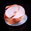
If the are is a visible area and you can't get in there with big files and such then use some solder wick,

s-l1600.jpg
liberally soak the area in flux, place the wick on the blob of solder and place a hot iron on top of that, once the wick is hot enough it'll whip up any solder on the surface. I then tend to use the iron as a mop with a towel on the end kind of effect and shove the wick around the area to mop any solder.

Remove the iron and wick together or else the wick will stick to your model :p

Done correctly you'll be left with a thin smear or witness stain of solder, which can easily be removed with a fibre brush.

A word of caution, the wick is 'very' good at conducting heat, you will get your second burnt finger very quickly if you hold onto it for too long ;) In time you'll find the best way to hold, adapt and use the wick, everyone has different techniques.
 
Top