I was asked by the owner of these fine looking GW Engines if I would have a look at one to see if I could put it right. This resulted in a succession of engines that required surgical treatment.
Summing this up, my main requirements for an engine that performs as it should are:
1. Compensation to give a 3 point suspension, thus ensuring that all the driving wheels were able to carry the weight of the loco where it mattered and provide maximum traction.
2. Current collection: In the past I have tried forms of pick ups ranging from bronze wire springs rubbing on the back of the wheels to spring load plunger pickups doing the same thing. I have found they are notorious for collecting dust which accumulates under the pickup point and eventually lifting the collector away from the wheel. The result ! interrupted current flow and uneven running or not starting at all .As a result of these experiences I decided to adopt a system put forward by some notable modellers from the past and tried using split axles and insulated bearings for the pickups. The differencewas remarkable and I have now used this method for the last 30 odd years.
With my friend (King John) we have improved our manufacturing techniques and developed jigs to standardise production of the axles and axle boxes to suit our requirements.
With the prospect of building a SR Merchant Navy rebuilt and no acceptable cast iron wheels to use I looked at Slaters wheels and decided to use them and try and modify them to suit my way of chassis building as previously described.
The first thing I tried was making a connection from the wheel rim to the brass centre using a very fine section of adhesive copper foil. Then I tried a fine wire to do the same and cutting a small groove down the length of a spoke to contain the wire. This may have worked if I had been able to make a satisfactory solder connection between the rim and hub but I found the heat was affecting the plastic body of the wheel, so I abandoned that Idea and put my thinking cap on and went to bed.
I woke up the next morning with an Idea to try and make the wheel behave as an all metal wheel. This involved a drastic modification to the wheel ( I was only using one wheel at this stage because I was not certain it would work).
The wheel was set up in an aluminium collet chuck which I use to grip the wheel by the tread and then the back of the plastic part was machinedaway to a suitable depth to allow a tinplate disk to be pressed into it. The hub of the wheel was bored out and a new brass hub to be inserted. This was then bored out to allow a split axle to be inserted. I checked the electrical resistance between the rim and the axle and found it to be very good. I was halfway to a metal wheel. The wheel was also very true running, another important point.
I made a jig to turn the disks I needed and also enable the holes to be drilled to accurately line up with those of the wheel and the disks were then soldered to the new hubs and then pressed into the machined Slater’s wheels. The crank pin holes were bored out to suit new steel crankpins and secured with a CS screw from the back of the wheel to ensure they would also carry current.
The wheels were then quartered ( I know the loco has 3 cylinders but mine has only two hence they are 90degs apart)
I am very pleased how they turned out and with the S7 etchings fitted they really look the part and test on the chassis worked very well.
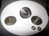
I have attached a photo to show the jig for making the back plate and also the plate before drilling and also the hub soldered on.
Another article will follow on the axle boxes and current collection.