simond
Western Thunderer
Quite a while ago, I impulse-purchased a very basis CNC milling machine to see if I could use it to make bits of model, and, as an aside, to help my understanding of G-Code, which is (in various dialects) pretty much the standard “language” by which commands are passed to the baby machine’s big brothers & sisters in industry.
The machine is very similar to this one; https://www.amazon.co.uk/VEVOR-Engraver-Engraving-160X100X40mm-Material/dp/B07VTZXW6D/ref=sr_1_11?crid=36T994MK8NQWL&dchild=1&keywords=vevor+engraving+machine&qid=1601733261&sprefix=VEVOr+engra,aps,147&sr=8-11
And cost around £140 from memory, it appears that they are still similarly priced, and it was cheaper than buying an adaptor kit, steppers, controller, etc., for my baby Proxxon Miller. For a few quid more you can now get a solid state laser that fits on the same gantry to interchange with the motor. (There are a couple of DIY laser threads on RMWeb if anybody’s interested. I’d not be running any kind of laser without some guarding!)
The miller comprises a fairly chunky 12V motor mounted in a 3-D printed holder, which forms part of the Z (vertical) axis. This slides on the X (side to side) axis which comprise a pair of 10mm ground steel rods mounted on the frame. The table on mine is 100 x 160mm. It is an aluminium extrusion, mounted on well made 3D printed bearing carriers, with sealed bearings, again on 10mm steel rods, which are also mounted to the chassis frame. The table moved fore & aft, giving the Y axis.
As supplied, there are 3 steppers and an Arduino based control board. It needs a decent 12V supply, and a usb connection to a laptop running any of the freeware control programs. There were no limit switches included, so I made my own. Optional, but difficult to use without.
Does it work?
well, yes, undoubtedly, it does what the Amazon advert says, but it has some weaknesses, which probably, nay undoubtedly, go with the price.
It cuts plastic quite well, and I guess would also cut wood, though I’ve not tried.
It seems pretty repeatable, but there is no position feedback, so if you overload an axis, it won’t necessarily stop and could lose steps, thus it’s position.
The motor mount is not rigid enough and mine cracked when I got ambitious tightening it. It now sports an old G cramp stopping the motor moving relative to its cradle, until I can make something better.
Cutting brass requires some patience. The whole structure needs stiffening and I have a cunning plan...
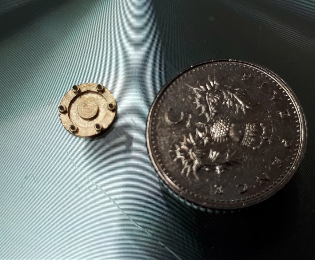
I have finally convinced it to make some buffer spacing plates for my Garratt, and it is cutting at around 0.2 mm/ sec, with a depth of cut of around 0.17mm, on 1.1mm thick brass.
The plates are 7mm square so I turned some washers with a 4mm hole and 10.7mm OD to the required thickness, and mounted each one on a post as the photo shows. The G-code I wrote is also attached, it goes to the centre of the post, switches to incremental control, offsets to beyond the corner of the plate, then executes a “square spiral” with radiussed corners to produce the plate. It takes 26minutes and 20 seconds to run. I have no doubt whatsoever that squaring up a bit of bar in my milling machine, and then turning it in the 4-jaw would have been quicker and far less hassle, but I’d not have had all the fun (or learning).

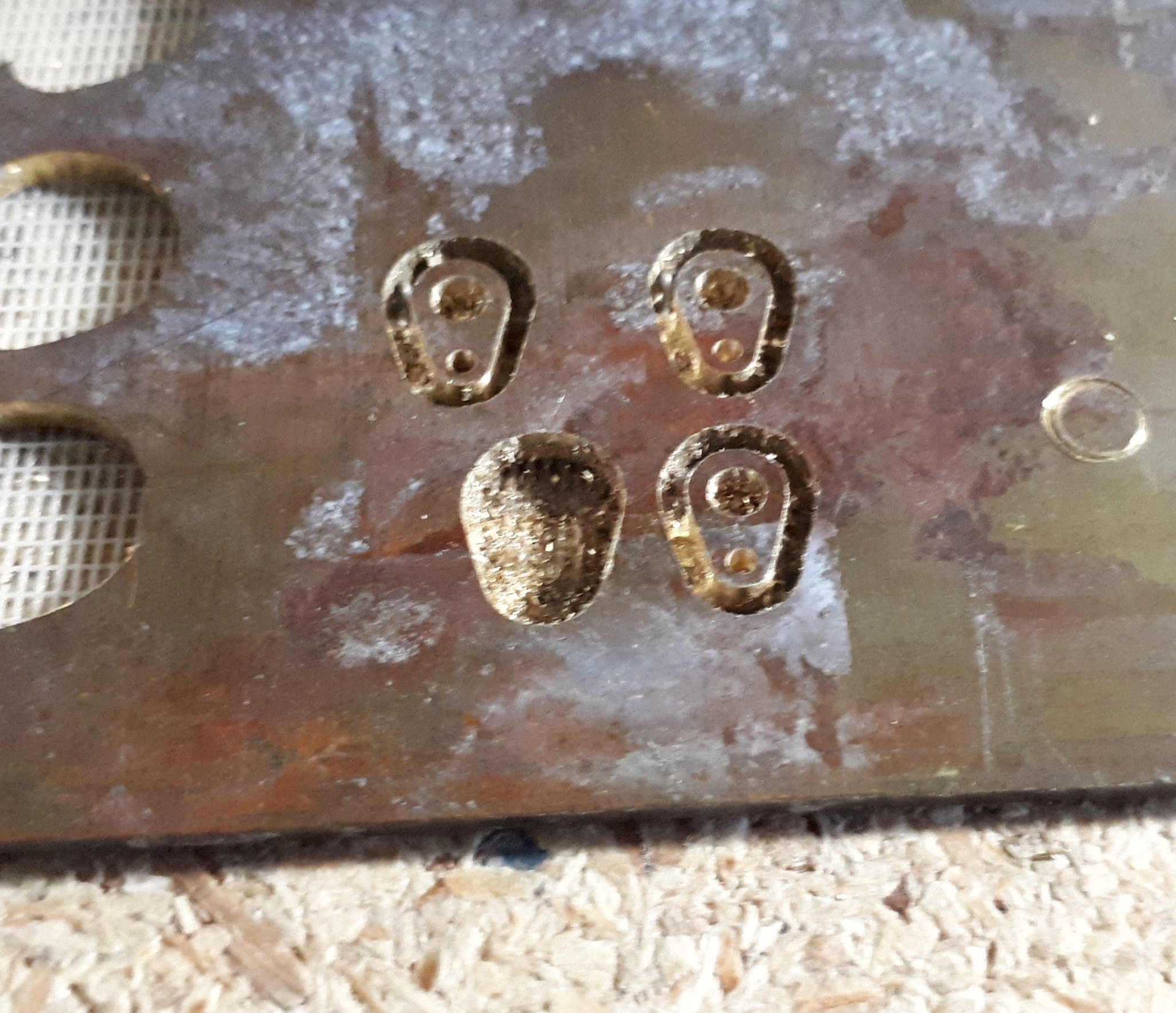
And here are some I made earlier, bad, and good...

Robin / Boy Blunder & I had a pm-chat a couple of months ago on the subject, and he purchased a newer version, so I hope he will add his experiences to the thread. If anyone else has a micro CNC mill or is pondering, please also join in.
Couple of other thoughts, I’m currently using “grblControl” to drive the machine, I tend to generate 2D cad on TurboCad because I’ve got it and have used it for at least 30 years. If / when I get into 3D milling, I’ll use Solidworks, which we have at work, and which I can remote-desktop to when required. There are lots of DXF - to - Gcode programs available which I have started to investigate. You can write & edit Gcode in notepad, or any other text editor, and there are lots of guides online.
Gcode - main commands are
G0 (that’s a zero) followed by an X, Y, and/or Z coordinate - the tool will go by the shortest route from current coordinates to those specified.
G1 as above but at a specified feed rate
G2 as above with extra coordinates will give a clockwise radius
G3 as G2 but anti-clockwise
F and a value for feed rate
M3 clockwise spindle (can also specify speed)
M5 spindle stop
loads more - Wikipedia provides a good list to start with.
Atb
Simon
The machine is very similar to this one; https://www.amazon.co.uk/VEVOR-Engraver-Engraving-160X100X40mm-Material/dp/B07VTZXW6D/ref=sr_1_11?crid=36T994MK8NQWL&dchild=1&keywords=vevor+engraving+machine&qid=1601733261&sprefix=VEVOr+engra,aps,147&sr=8-11
And cost around £140 from memory, it appears that they are still similarly priced, and it was cheaper than buying an adaptor kit, steppers, controller, etc., for my baby Proxxon Miller. For a few quid more you can now get a solid state laser that fits on the same gantry to interchange with the motor. (There are a couple of DIY laser threads on RMWeb if anybody’s interested. I’d not be running any kind of laser without some guarding!)
The miller comprises a fairly chunky 12V motor mounted in a 3-D printed holder, which forms part of the Z (vertical) axis. This slides on the X (side to side) axis which comprise a pair of 10mm ground steel rods mounted on the frame. The table on mine is 100 x 160mm. It is an aluminium extrusion, mounted on well made 3D printed bearing carriers, with sealed bearings, again on 10mm steel rods, which are also mounted to the chassis frame. The table moved fore & aft, giving the Y axis.
As supplied, there are 3 steppers and an Arduino based control board. It needs a decent 12V supply, and a usb connection to a laptop running any of the freeware control programs. There were no limit switches included, so I made my own. Optional, but difficult to use without.
Does it work?
well, yes, undoubtedly, it does what the Amazon advert says, but it has some weaknesses, which probably, nay undoubtedly, go with the price.
It cuts plastic quite well, and I guess would also cut wood, though I’ve not tried.
It seems pretty repeatable, but there is no position feedback, so if you overload an axis, it won’t necessarily stop and could lose steps, thus it’s position.
The motor mount is not rigid enough and mine cracked when I got ambitious tightening it. It now sports an old G cramp stopping the motor moving relative to its cradle, until I can make something better.
Cutting brass requires some patience. The whole structure needs stiffening and I have a cunning plan...
I have finally convinced it to make some buffer spacing plates for my Garratt, and it is cutting at around 0.2 mm/ sec, with a depth of cut of around 0.17mm, on 1.1mm thick brass.
The plates are 7mm square so I turned some washers with a 4mm hole and 10.7mm OD to the required thickness, and mounted each one on a post as the photo shows. The G-code I wrote is also attached, it goes to the centre of the post, switches to incremental control, offsets to beyond the corner of the plate, then executes a “square spiral” with radiussed corners to produce the plate. It takes 26minutes and 20 seconds to run. I have no doubt whatsoever that squaring up a bit of bar in my milling machine, and then turning it in the 4-jaw would have been quicker and far less hassle, but I’d not have had all the fun (or learning).
And here are some I made earlier, bad, and good...
Robin / Boy Blunder & I had a pm-chat a couple of months ago on the subject, and he purchased a newer version, so I hope he will add his experiences to the thread. If anyone else has a micro CNC mill or is pondering, please also join in.
Couple of other thoughts, I’m currently using “grblControl” to drive the machine, I tend to generate 2D cad on TurboCad because I’ve got it and have used it for at least 30 years. If / when I get into 3D milling, I’ll use Solidworks, which we have at work, and which I can remote-desktop to when required. There are lots of DXF - to - Gcode programs available which I have started to investigate. You can write & edit Gcode in notepad, or any other text editor, and there are lots of guides online.
Gcode - main commands are
G0 (that’s a zero) followed by an X, Y, and/or Z coordinate - the tool will go by the shortest route from current coordinates to those specified.
G1 as above but at a specified feed rate
G2 as above with extra coordinates will give a clockwise radius
G3 as G2 but anti-clockwise
F and a value for feed rate
M3 clockwise spindle (can also specify speed)
M5 spindle stop
loads more - Wikipedia provides a good list to start with.
Atb
Simon
Last edited:
 CNC cylinder end cover


 2020-10-05_04-58-56
 2020-10-05_04-56-38


