Nick Dunhill's workbench CR 0-4-4T Wrexham Tanks

Nick Dunhill

Western Thunderer
....a big week with the Wrexhams, I've been working on all the mundane bits and pieces that are often overlooked.


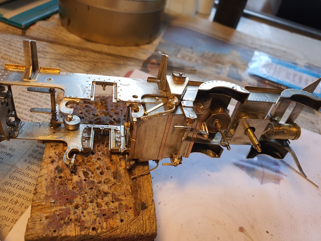
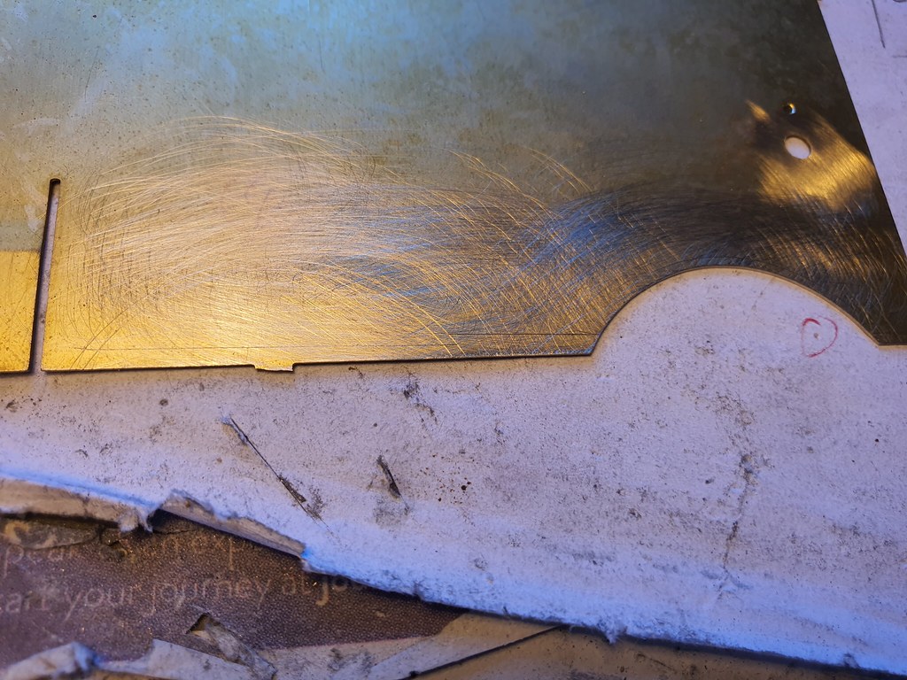
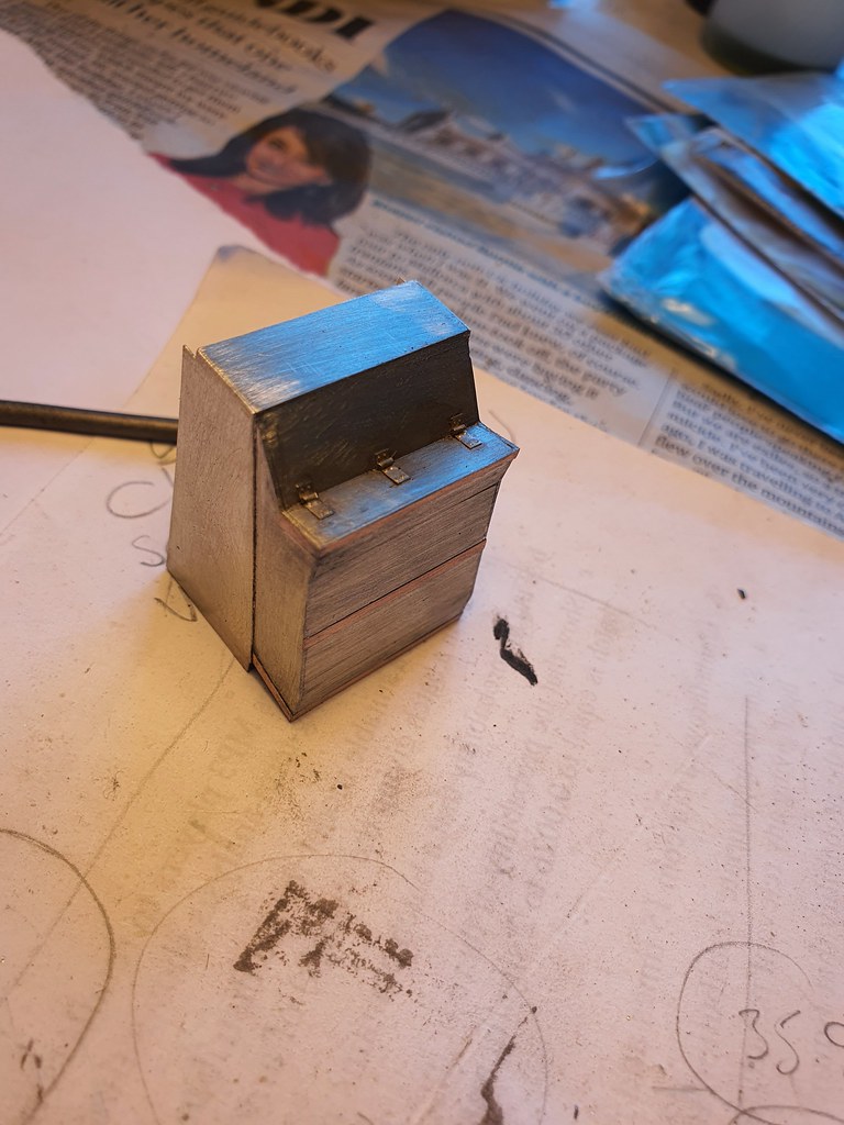
First I completed a bit more work on the firebox bottom and ashpan. The damper doors were detailed with straps and hinges. The rest of the detail will be added when they are installed.


49951275698_7fff5f967d_b.jpg


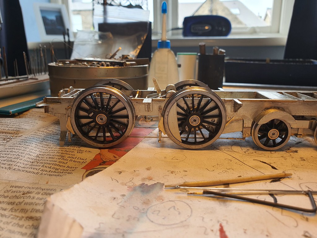
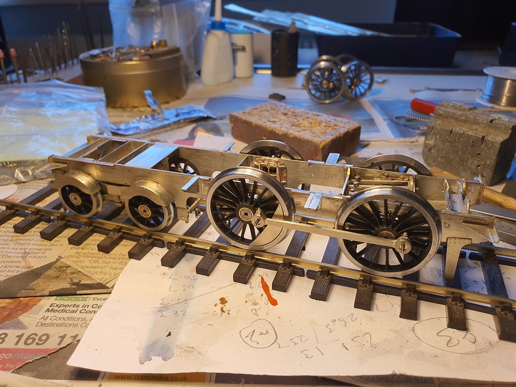
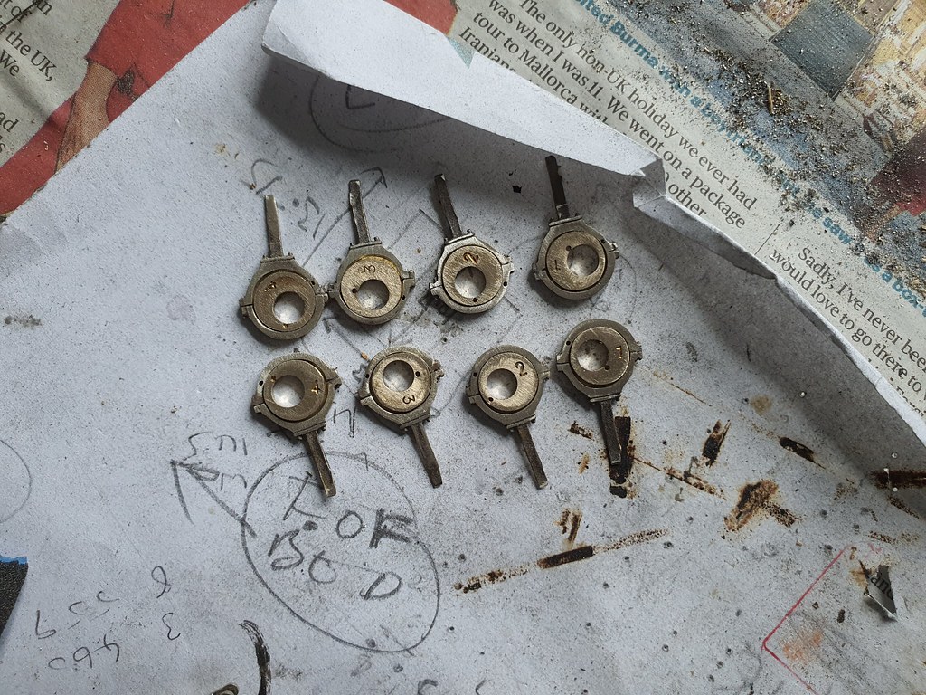
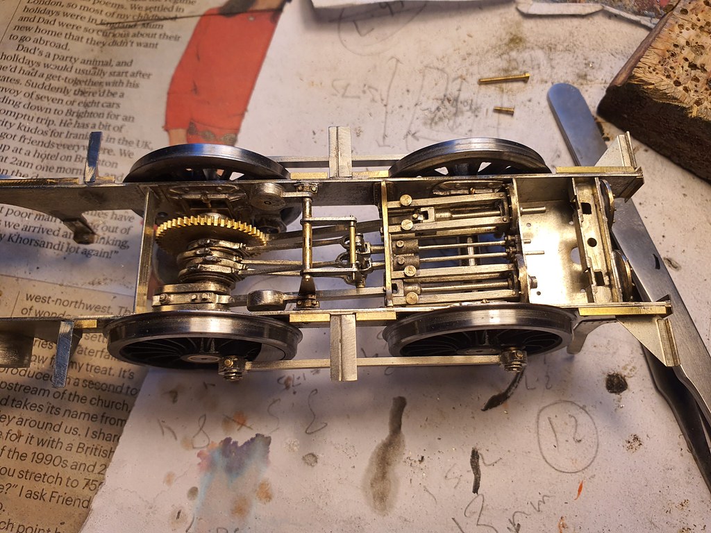
Then I moved on to the hornguides. I couldn't find any commercially available cast ones. They're all the wrong pattern or too large to fit between the slidebars and frame, or the crank webs and frame. I considered scratchbuilding some but in the end opted for some Gresley etchings from the Finney7 Coop. They have the wedge adjusters so are handed as prototype, and could be modified relatively easily. The horncheeks are much reduced in height and I added wedges from 1 mm square rod and all the webs.


49951776746_1e5469de0f_b.jpg


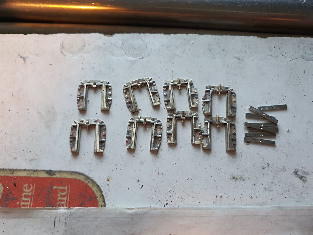
I added some 14BA screws and nuts as height adjusters. They're brass items which can be soldered up when all is level.


I like self contained buffers as the fixing screws don't interfere with the gusset structures that support the buffer beams from behind. The semi tapered GWR Dean (?) buffers were an excellent match, and I bought sets of them from Haywood Models. The GWR version of the buffers have a tread on the stocks which my locos don't, but being white metal they are easy to file off.


49951275773_4d5609e6c0_b.jpg


The fixing studs and nuts are represented by a cast pip that's just a bit lame! I filed them off and will add some fake fastners from GHW-Modelbauversand in Germany. They're cheaper than the ones from Scale Hardware in Florida as we don't have to pay import duty or VAT on them for the time being (thanks Brexiteers!)


My plan was to drill out the buffer bodies all the way through and cut off the unnecessary housing on the rear. The stocks were already partly drilled out to 2 mm, so I just continued on through. The buffer heads have a shank that is much less than 2 mm at the head. I decided to sleeve the shanks out to stop the heads rattling about in them. The sleeve conveniently holds the buffer spring captive inside the stock. I made some guide/stops for the inside of the stocks, and glued them in place using a drill and tape repurposed as a locating tool.


49951276068_4ae0af09a6_b.jpg


49951941886_4784d9321f_b.jpg


49951777586_3b409c4912_b.jpg


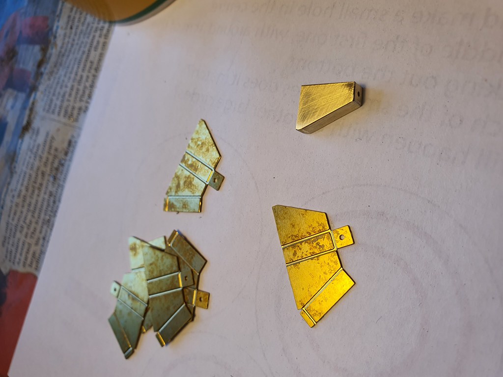
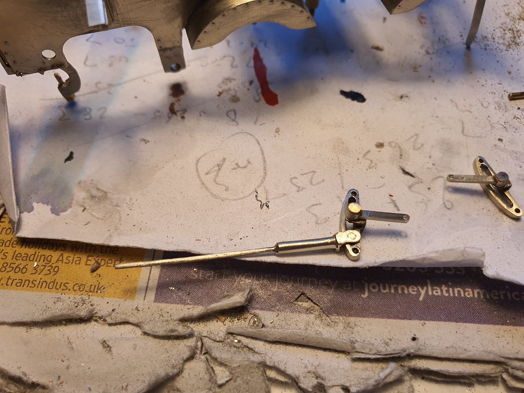
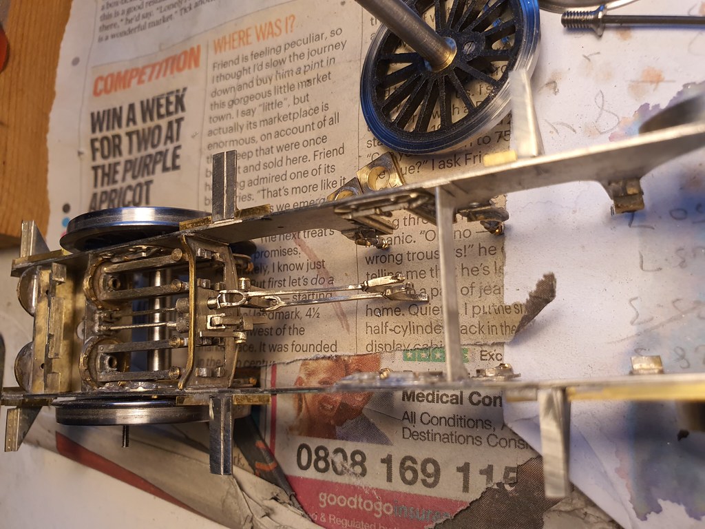
I went on to make some spring hangers next, 16 of them and handed. The photo shows how I did it.


49951277023_02a9c056e3_b.jpg


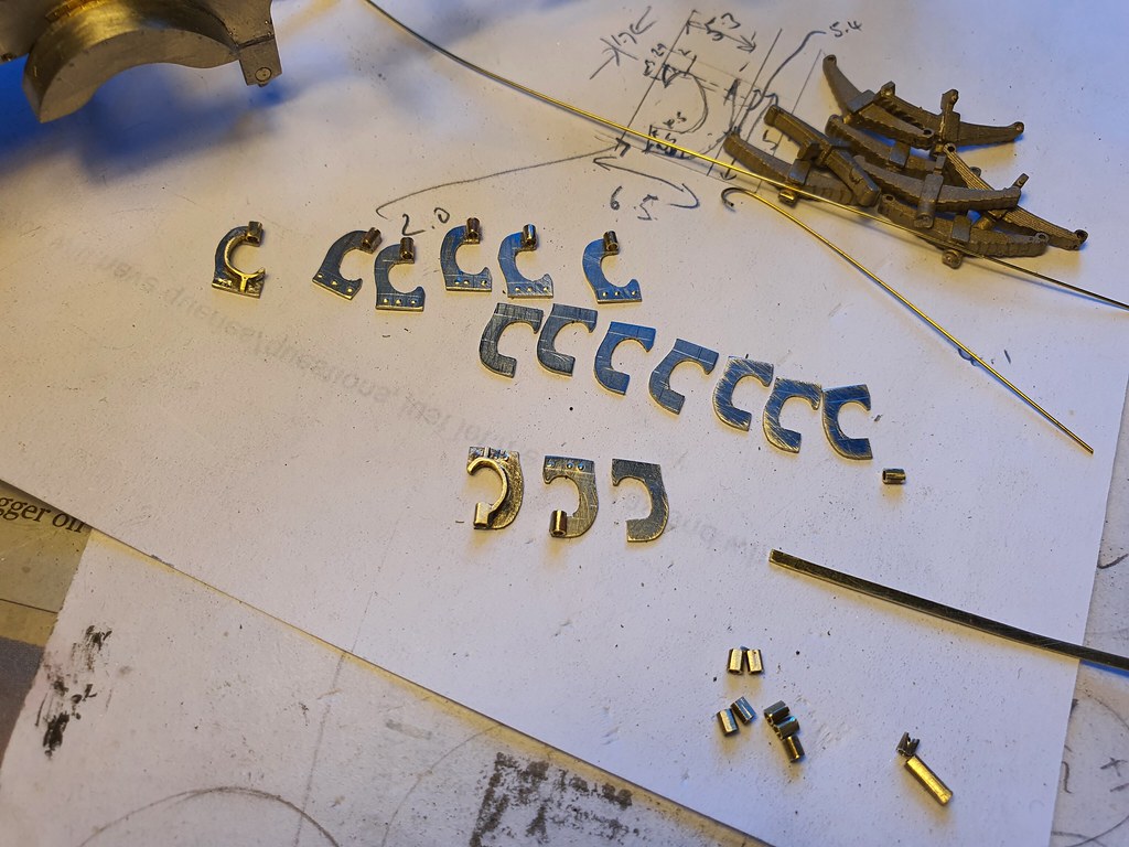
They were a lot of effort but will look good on the model. They are on show through the spokes too.....


49951277193_32cee4dc9f_b.jpg


Hopefully next week I can finish the springs, build some coupling rods and instal everything else......
 

paulc

Western Thunderer
Hi Nick , i have just caught up with this build , lovely stuff . Ref you question about compression springs , i get mine from the local locksmith and are the detent springs used in the barrel where your key slides in . They usually come in plastic sleeves of 10 .
Cheers Paul
 

ICH60

Western Thunderer
"fake fastners from GHW-Modelbauversand in Germany"

Thanks for the site, well worth the look.
 

Nick Dunhill

Western Thunderer
...so after making up bits and bobs last week I could get on and assemble them this week!

49974150881_3f178a40b2_b.jpg


First up the spring hangers, quickly followed by the front horn guides.

49974411472_99500dd61e_b.jpg


As you can see I quickly added mounting rods and adjusters. The springs are mounted on the keeper plates, and will be added once painted. I used my trusty jury axles and the coupling rods to locate the rear horn guides to ensure a smooth running chassis.

49974152551_7300301cc0_b.jpg


49974411257_5587a276d8_b.jpg


The etchings for the rods turned up this week too, great just-in-time delivery.

49974152911_afa25a6d05_b.jpg


After a bit of faffing about I had a nicely running chassis. The bogie works well and doesn't short out on the mud guards. As a belt and braces measure I lined the inside of the mudguards with insulation tape and turned 0.5 mm off the diameter of the bogie wheel flanges. The side to side motion of the bogie was restricted to a minimum and the side control turned out to be more than adequate.

49973635083_b857d2b286_b.jpg


49974154341_6a3557e686_b.jpg


49974413112_03312be155_b.jpg


So there we have a couple of running chassis with footplates and buffers (the fake nuts and bolts turned up from Germany.) Next I'll either build the rest of the brake system or the inside motion, depends how I feel on monday morning. Enjoy the weekend........
 

Nick Dunhill

Western Thunderer
...so inside motion it was. I've built a few LGM sets of inside motion and they're pretty comprehensive. Laurie mixes and matches castings fffrom his rage for you to get the most appropriate stuff. Because of their universal nature they do need a fair bit of fiddling and fettling to get them to fit. The eccentric straps are now cast in two halves, but they still have an ID when assembled that's less than the OD of the eccentric sheaves. When the straps are assembled mine had some distortion from the casting process, so weren't round either. It took a lot of grinding and filing to make the eccentrics fit the straps, but I got there in the end.


49998953317_2ffc944ca1_b.jpg


Similarly the big end eyes of the connecting rods are a much smaller diameter than the cast crankpins on the cranks, file, file, file etc. And just as my patience and finger ends are getting a but frayed I found the crank webs aren't parallel, or anything like square. A cup of tea and sit down later and I tried tweaking a crank casting before packing them up and sending them off for replacement. They aligned pretty well after some prying in a vise, success.


49998953117_6639ab6d49_b.jpg


I made a jig for attaching the eccentric rods to the straps (measurements taken from GA.)


49998181483_6f2ed3747c_b.jpg


The eccentric rods have to be cut to length and scarfed to the strap casting. The rod castings are pretty badly cast too. They're wobbly and not of constant thickness, but never the less with a bit of care I got a decent set of rods.


49998953577_2e0e2bfb9a_b.jpg


So on to assembly, first I pinned the valve rods to the expansion links and then the eccentric rods.


49998953902_18ced7006d_b.jpg


49998702431_e66ca9e582_b.jpg


Next the weighshaft and lifting links.


49998702886_72c288bb73_b.jpg


And finally I assembled the crank axle and cut the axle from between the webs.


49998955902_6d4203a224_b.jpg


I just solder them. I did get a very nice running chassis though, although no video until I rig up the layshaft and motor.


49998955767_f5b3676a06_b.jpg


Brakes next week........
 

Nick Dunhill

Western Thunderer
Some of it. But the alternative would be a gearbox and gears. But really it's all hidden by the water tanks, including all my fine rods and eccentrics......
 

Steph Dale

Western Thunderer
One of the effects you get with some locos (including LSWR M7s) as they run is down to being able to see the crank behind the frame. I'm conscious that your locos have very deeper frames than most - that's why I was asking. It's also been the challenge and reason for building the driven-crankaxle gearboxes I've been working on.

Looking good so far :thumbs::)

Steph
 

Scale7JB

Western Thunderer
Having the eccentric straps in two halves is not such a bad idea, more work but less likely to solder everything solid by mistake which I think I did do once.

Looking nice and shiny though :thumbs:

JB.
 

Nick Dunhill

Western Thunderer
.....I have moved on to the brake rigging. The shoes and hangers were an amalgam of some etched hangers on the original Mick Davies derived fret and the shoes from the Redcraft etch. The pull rods and spreaders were also in the MD panel but were modified a lot. Anyway I ended up with lots of small parts.


50023136251_d490260b14_b.jpg


They assembled up into the brake arrangement shown here. The rigging is detachable so the crank axle can be removed for painting.


50022594148_3a37faa7dd_b.jpg


50023136646_87e7731c25_b.jpg


50023136731_d2840e3e0c_b.jpg


Next I made the sand hoppers from the Redcraft etches. They had sloping filler covers which had to be scratchbuilt.


50023136651_d2ef2d0bf6_b.jpg


50023137031_72b61e3922_b.jpg


The hoppers were attached to the chassis and augmented with some cast pipes and fittings from Laurie Griffin.


50023137186_bc966476fe_b.jpg


50023393897_21d93ab3bf_b.jpg


I need to attach the steam pipes to the sanders and also attach cylinder drain cocks. I'm not sure whether the drain cocks are steam or mechanically operated, anyone know?.......
 

Nick Dunhill

Western Thunderer
.....Well here's a picture of the completed cylinder drain cocks and all the plumbing, including that to the sanders.

50047042043_2967db9eb4_b.jpg


I found a pack of 4 mm Alan Gibson plunger pick ups in an old, old box from my OO days. They looked small and discrete so I decided to fit them. I decided plunger pick ups would disappear in the cylinder block and ashpan, but I didn't want them to interfere with the layshaft gearbox. So next I made the layshaft gearbox.

50047042848_8d230daf8e_b.jpg


It is quite a simple assembly, but it does allow the gears to mesh very nicely.


The gears stay in mesh as the compensation moves the crank axle and gear up and down slightly. Engineers comment here; ________

Sorry about R4!

Oh, and here's the Gibson pick ups installed


Next I did a test fit of everything to make sure there were no conflicts of parts.


Next it was time to tackle the body, so I made some splashers. 16 crescent shaped front plus 4 for the coupling rod bosses. The front driving wheel splashers have brass beading so...


So here we are at the close of play today.


Next I'll make splashers for the rear drivers and start the bodywork..........
 
Last edited:
Top