You are using an out of date browser. It may not display this or other websites correctly.
You should upgrade or use an alternative browser.
You should upgrade or use an alternative browser.
Nick Dunhill's workshop NGG16 Garratt
- Thread starter Nick Dunhill
- Start date
Nick Dunhill
Western Thunderer
Thanks Pete, they're scribed, but don't get too close!
Nick Dunhill
Western Thunderer
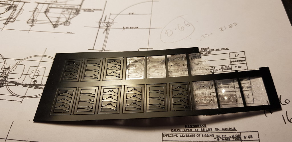
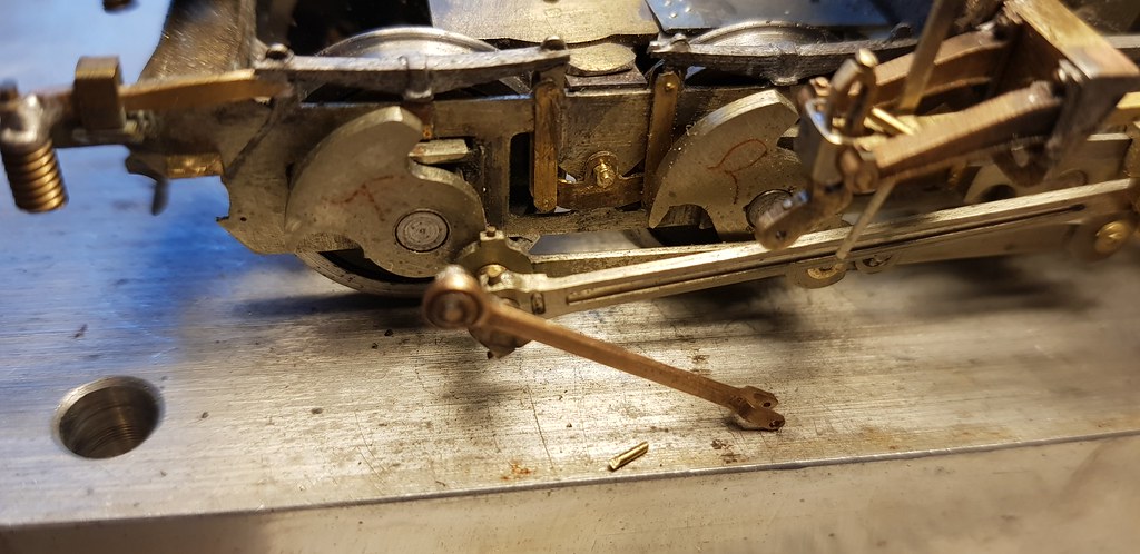
...having completed the motion, the logical thing is to dismantle it, clean it up and do a final assembly test with the correct pins etc and have a test run. I thought that this would also be a good time to fit the brake gear, so I have set about making it. Adrian of this parish has kindly lazer cut me some plastic brake blocks. Now this was an amazing gesture, so thanks very much Adrian, they were very successful. The 3 layers are stuck together with MEK, allowed to dry and pinned to some hangers cut from scrap nickel-silver strip.
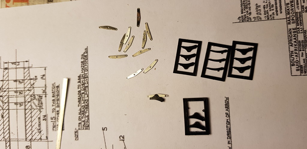
I have made some cross beams, also from scrap, and they are now fitted to the brake hangers.
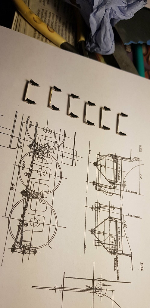
Brake linkages next...........
I have made some cross beams, also from scrap, and they are now fitted to the brake hangers.
Brake linkages next...........
Nick Dunhill
Western Thunderer
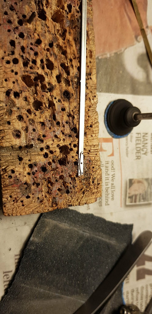
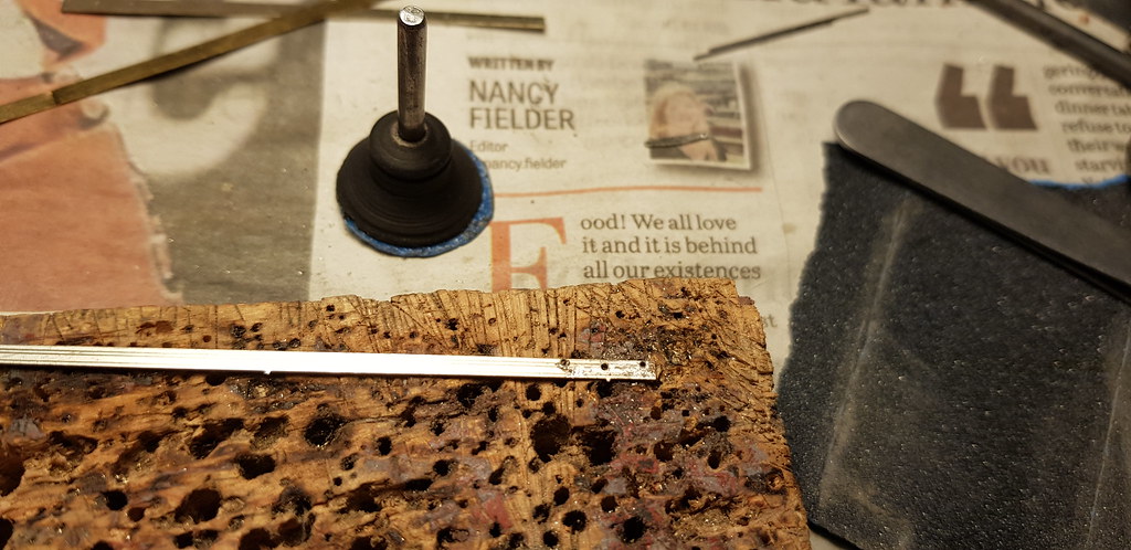
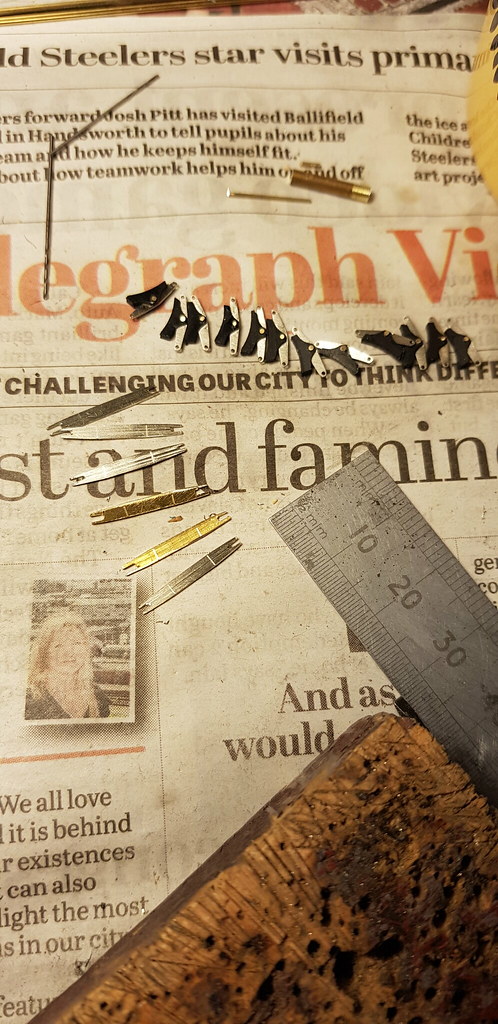
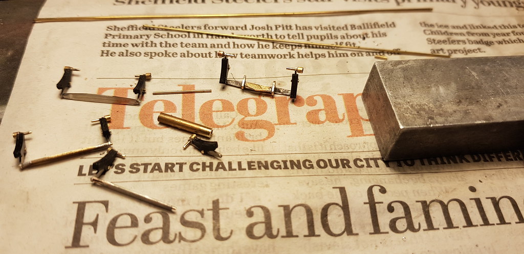
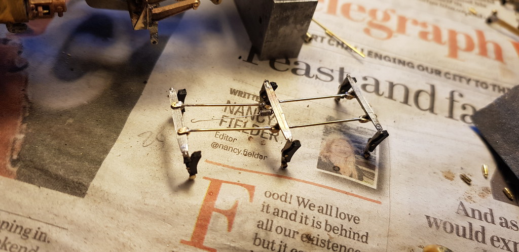
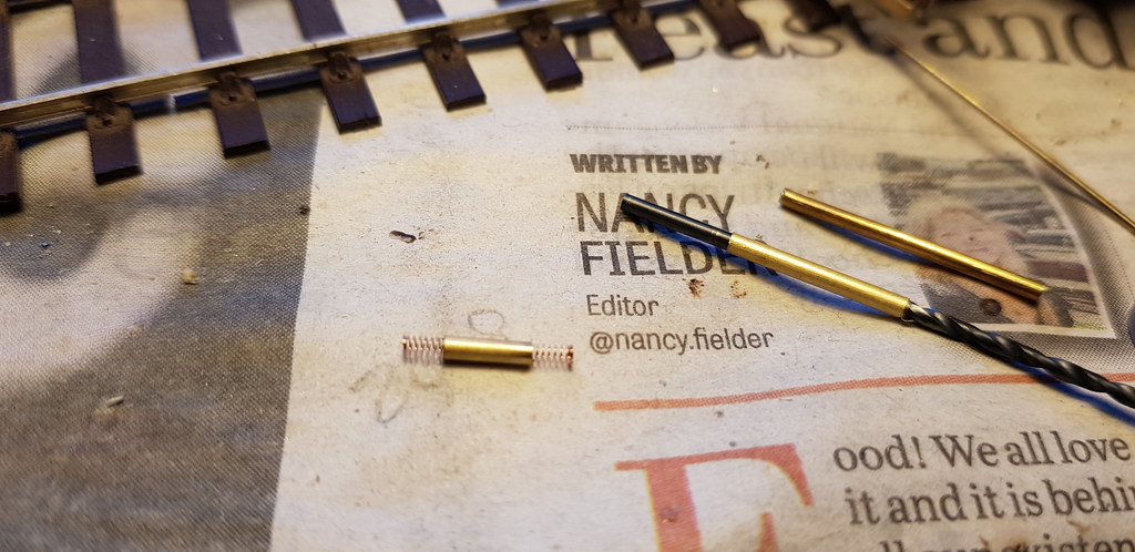
....the next stage was turning this pile of tiny bits of rod, spacers and other assorted tube into some usable brakes and cross beams.
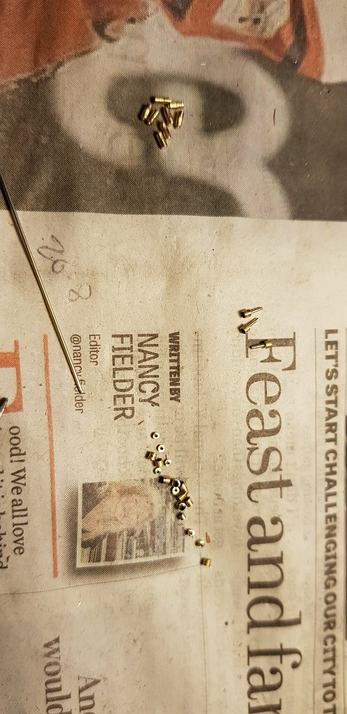
The parts were telescoped together and attached to the brake hangers.
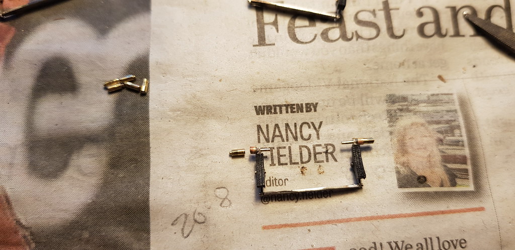
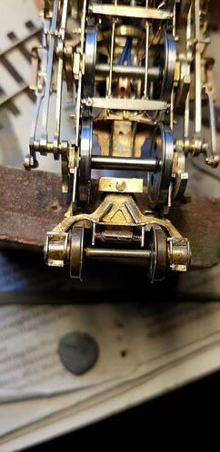
The idea is that I will slot the final assembly (when all the rigging has been attached) up into the chassis from the bottom, and pin it all in place with some locating dowels, pushed from the outside of the chassis frames. The hollow locating dowels have a hex formed on the end, and a 0.6 mm rod down the middle to represent the fixing bolt, showing on the outside of the chassis. As can be seen on this picture the locating dowels for the brake hangers double up as pivot bolts for the suspension equalising beams, just as on the real thing.
The cross beams have some shackles fitted for the rigging and an interesting pull-beam at the rear. I think this allows the brake rigging pull rods to pivot as the cradle and unit move in relation to each other.
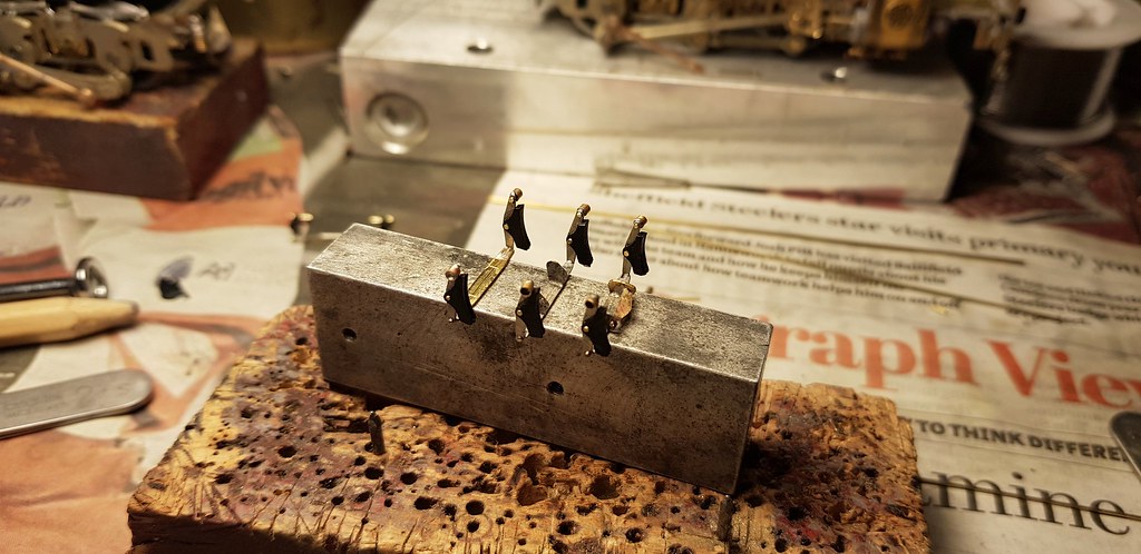
I'm sorry about the over complication the build is becoming the 'Project Binky' of loco chassis (see You Tube.) Next a million pull rods..........
The parts were telescoped together and attached to the brake hangers.
The idea is that I will slot the final assembly (when all the rigging has been attached) up into the chassis from the bottom, and pin it all in place with some locating dowels, pushed from the outside of the chassis frames. The hollow locating dowels have a hex formed on the end, and a 0.6 mm rod down the middle to represent the fixing bolt, showing on the outside of the chassis. As can be seen on this picture the locating dowels for the brake hangers double up as pivot bolts for the suspension equalising beams, just as on the real thing.
The cross beams have some shackles fitted for the rigging and an interesting pull-beam at the rear. I think this allows the brake rigging pull rods to pivot as the cradle and unit move in relation to each other.
I'm sorry about the over complication the build is becoming the 'Project Binky' of loco chassis (see You Tube.) Next a million pull rods..........
Nick Dunhill
Western Thunderer
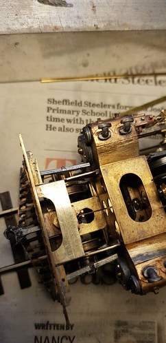
....I have mounted the brake assemblies in the chassis and joined them up with pull rods to make one complete removable brake assembly.
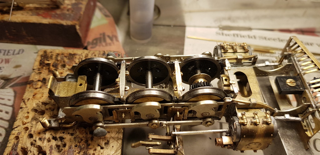
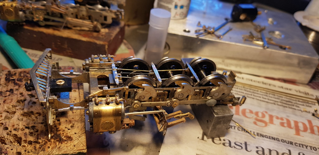
These are pinned into the chassis using the method outlined in the previous post. Since then the chassis have been fitted with pick ups and then stripped and cleaned.
Next will be the addition of the upper sections of the slide bars and connecting rod safety straps.........
These are pinned into the chassis using the method outlined in the previous post. Since then the chassis have been fitted with pick ups and then stripped and cleaned.
Next will be the addition of the upper sections of the slide bars and connecting rod safety straps.........
Nick Dunhill
Western Thunderer
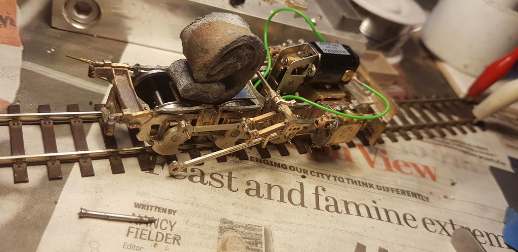
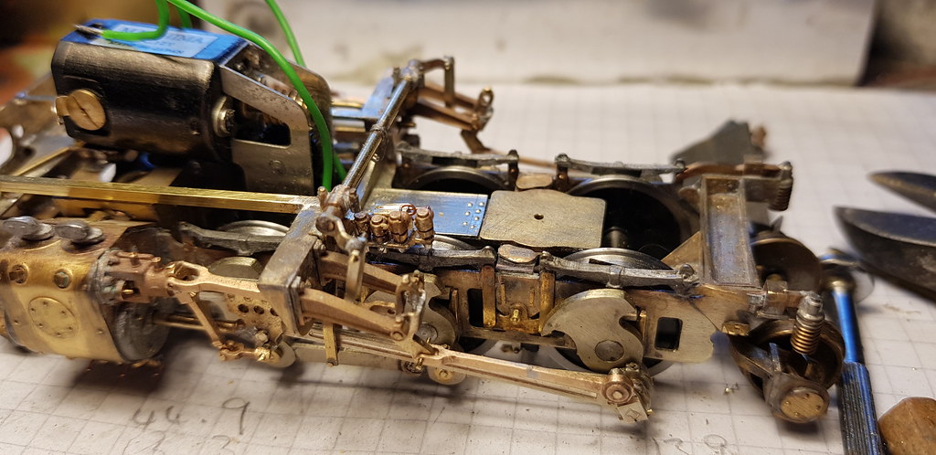
...The slide bar uppers have been added as has the con rod safety bracket.
The motion has been carefully assembled so it doesn't bind and I had a problem with a short that needed rectifying. After a couple of hours pulling out hair I discovered the short was on the front bogie. Over zealous shimming, the brass shims were replaced with fibre ones and all was well. I added side control to the front and rear bogies and did a test run. Both bogies were cockling over to one side while being pushed. You think there'a a lot of rail to flange slop in 7 mm, 4 mm is much worse!
Next I catch the other bogie up.....
Nick Dunhill
Western Thunderer
....assembling the hind unit and I've not had to resort to using my nail-gun yet!
Last edited:
Peter Cross
Western Thunderer
There's a lot of rotating mass on those frames.
Nick Dunhill
Western Thunderer
....Ha ha ha boom boom...
Nick Dunhill
Western Thunderer
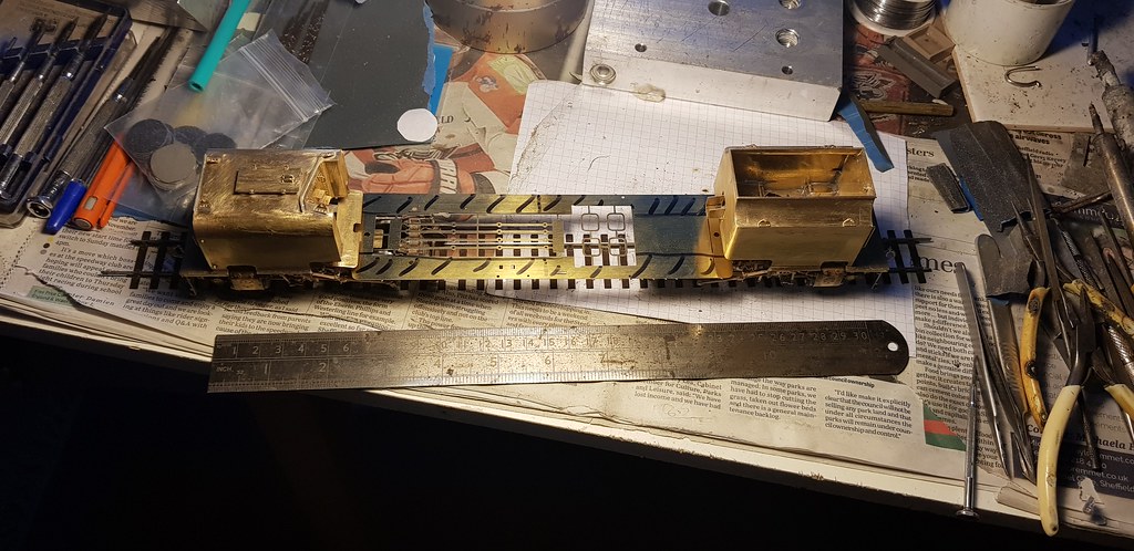
...big catch up. I added some vacuum pipes to both units and a representation of the steam and exhaust pipes to the cylinder blocks.
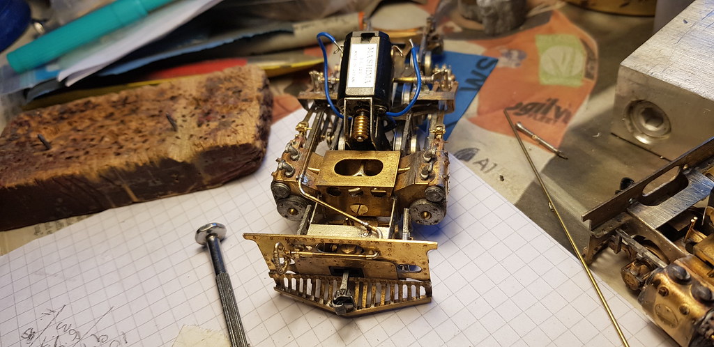

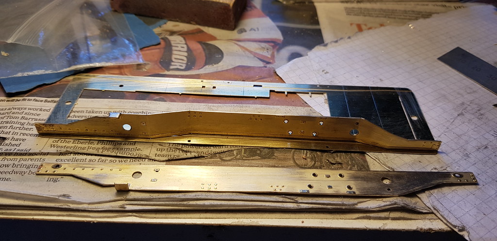
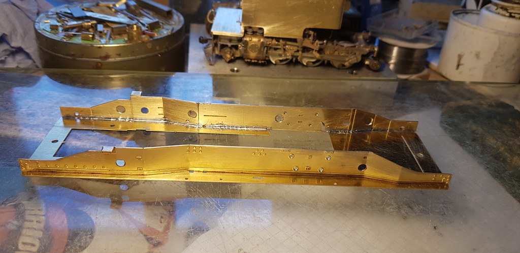
The chassis were then largely finished, so work on the superstructure began in haste. The footplates in the kit had lots of holes in the wrong place and the cut-outs for the cylinders didn't match the ones made by the WHR, so new ones were cut out.
Similarly the water tank built by the WHR is significantly different from the one in the kit, both in terms of rivets and dimensions. I used the basic dimensions from the etchings supplied to cut out pieces to make a new tank.
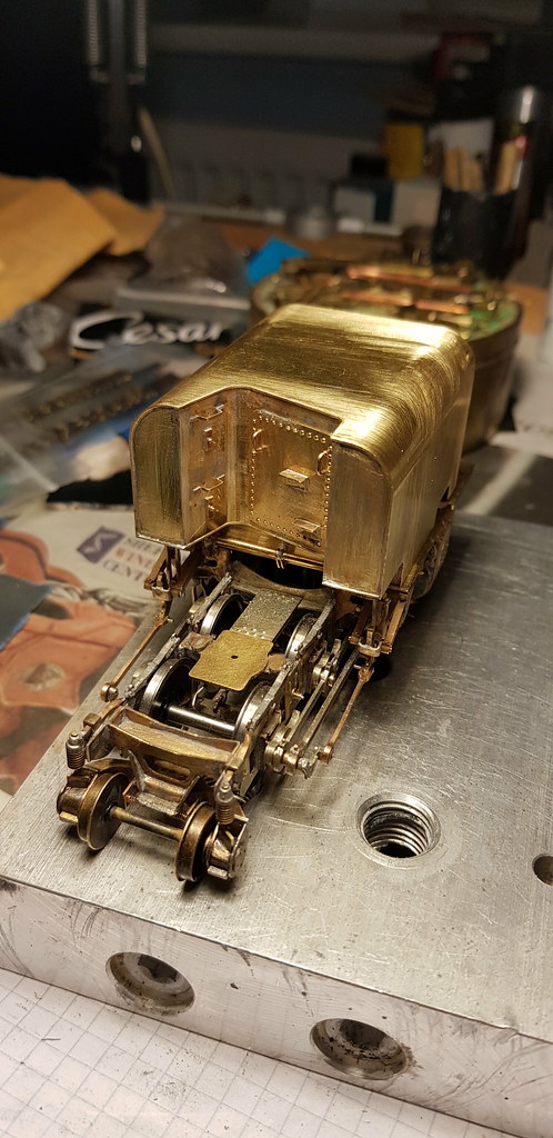
Looks more like an O gauge loco now! More detail tomorrow......
The chassis were then largely finished, so work on the superstructure began in haste. The footplates in the kit had lots of holes in the wrong place and the cut-outs for the cylinders didn't match the ones made by the WHR, so new ones were cut out.
Similarly the water tank built by the WHR is significantly different from the one in the kit, both in terms of rivets and dimensions. I used the basic dimensions from the etchings supplied to cut out pieces to make a new tank.
Looks more like an O gauge loco now! More detail tomorrow......
adrian
Flying Squad
Which one are you basing it on then? #87 in your first posting does have the riveted tanks - does this mean you are looking at #138 or #143 with a welded tank. Curiously Wikipedia says NG128 was the first with welded tanks but then the photo they have of #128 has riveted tanks!!Similarly the water tank built by the WHR is significantly different from the one in the kit, both in terms of rivets and dimensions. I used the basic dimensions from the etchings supplied to cut out pieces to make a new tank.
Nick Dunhill
Western Thunderer
Yes sorry that's a bit misleading Adrian. I started intending to do 87 but then some SAR modellers on another forum pointed out that 87 is more like a NGG12.5, and that the kit the boiler/cab etches are more like 138/143 (despite having to scratchbuild tank and bunker.) None of the G16s are like the kit!
So 138 it is.
So 138 it is.
Nick Dunhill
Western Thunderer
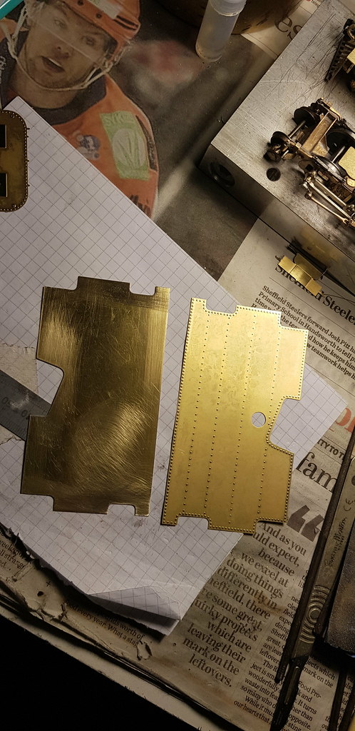
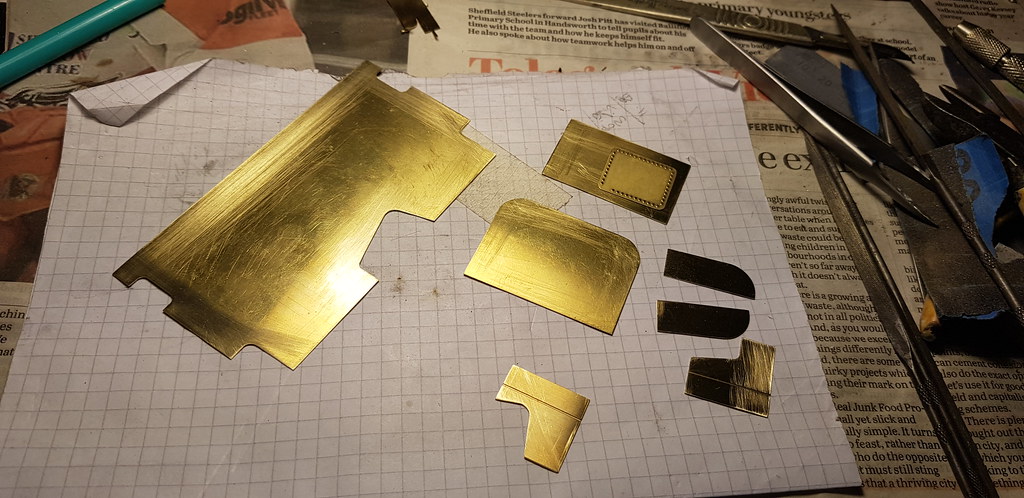
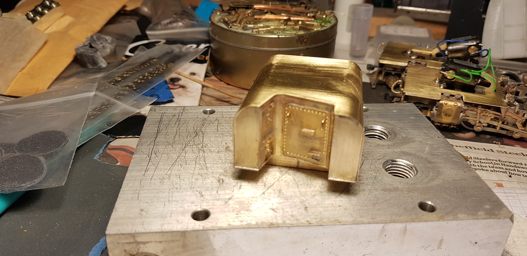
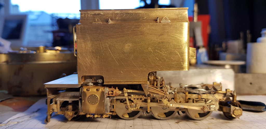
...well I tarted up the top of the water tank and moved on to the bunker. As with the water tank there are significant differences between the kit parts and the WHR modifications. The most significant being the lack of rivets, so it was out with the piercing saw.
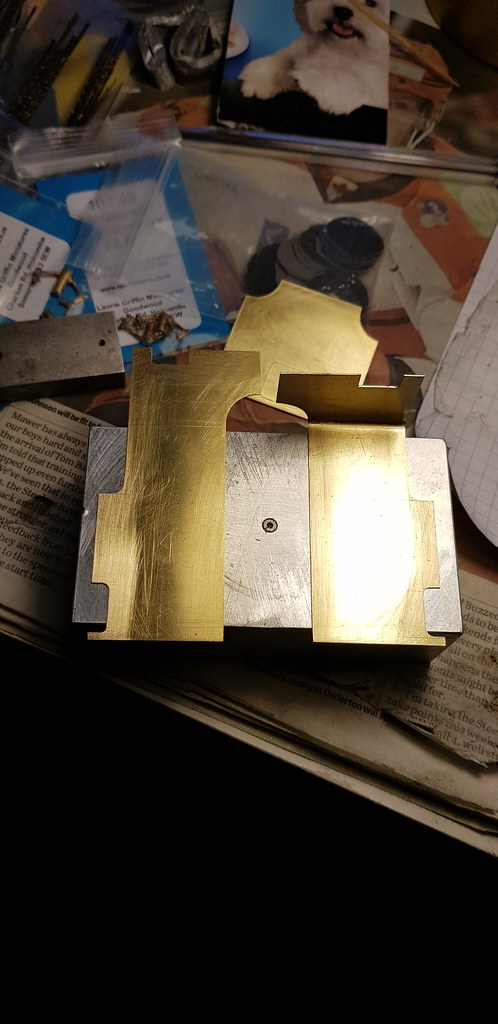
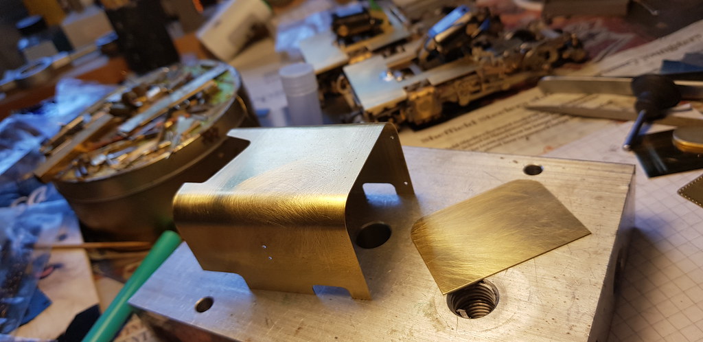
The kit parts were modified until they fitted and were as required. They were then flattened out and used as a template for the new parts cut from 0.4 mm sheet. The curve in the front corners of the side sheets were formed round the handle of a needle file, and the structure taped together as a test fit. All was well and the structure was soldered up and fettled.
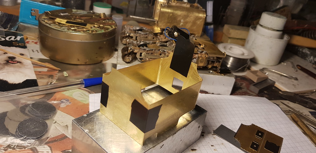
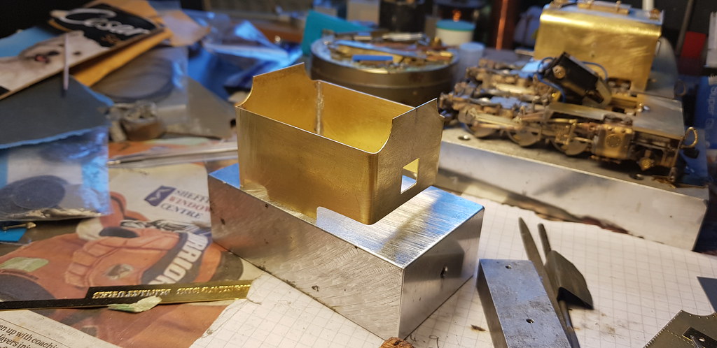
The kit parts for the curved bits on the bunker side did fit, but annoyingly they are half etched on the rear to aid curving. This produces a three-penny bit pattern on the front that looks awful, so they were discarded and new ones cut out. They were formed round a suitably sized bar and added.
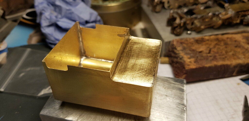
A floor was made and soldered in, and I went to lie down.
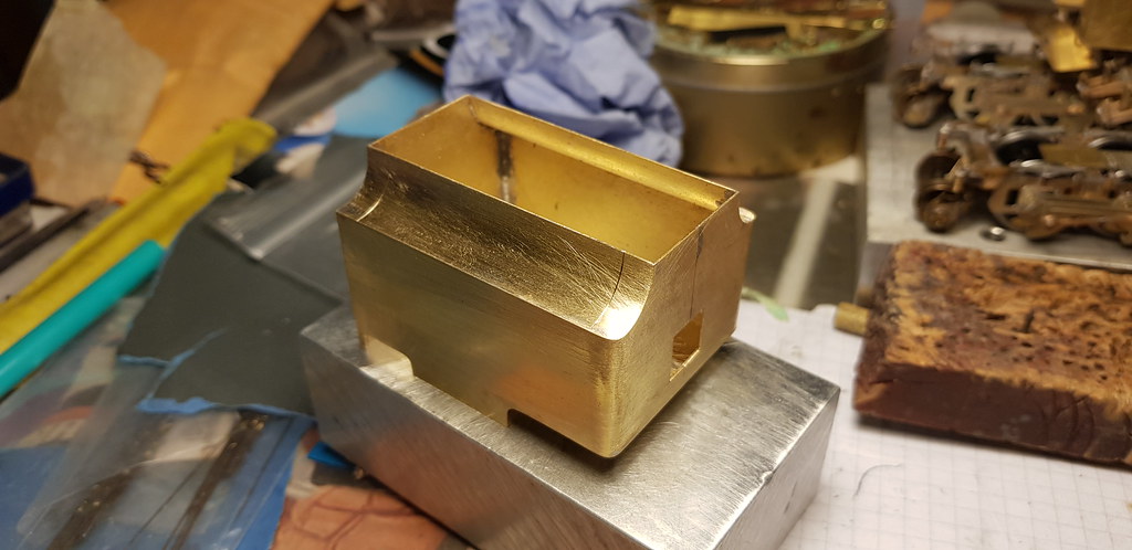
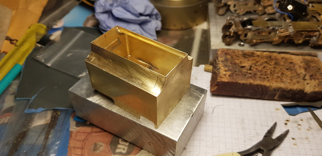
More detail tomorrow....
The kit parts were modified until they fitted and were as required. They were then flattened out and used as a template for the new parts cut from 0.4 mm sheet. The curve in the front corners of the side sheets were formed round the handle of a needle file, and the structure taped together as a test fit. All was well and the structure was soldered up and fettled.
The kit parts for the curved bits on the bunker side did fit, but annoyingly they are half etched on the rear to aid curving. This produces a three-penny bit pattern on the front that looks awful, so they were discarded and new ones cut out. They were formed round a suitably sized bar and added.
A floor was made and soldered in, and I went to lie down.
More detail tomorrow....
Nick Dunhill
Western Thunderer
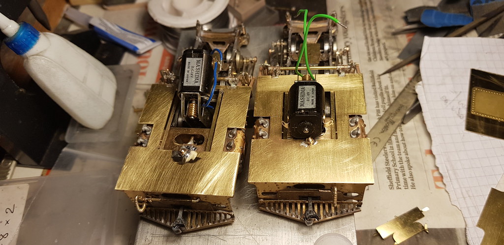
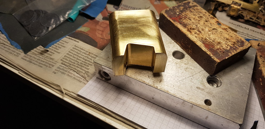
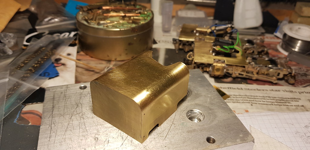
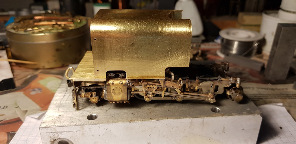
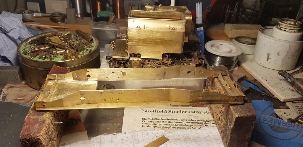
....moving swiftly on the bunker has been fully detailed and attached to the footplate.
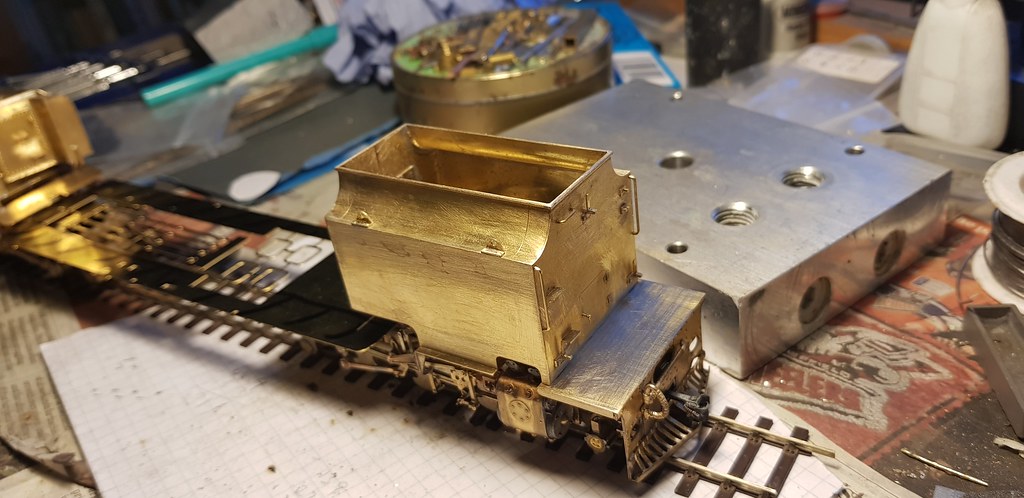

And as you can see I've mocked up the full length of the finished loco.
I've made up some lubricators that fit behind the motion bracket, and the units are finished for now pending delivery of some etchings from OZ.
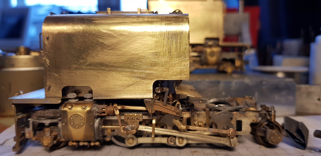
Tomorrow we begin the cradle, and initial investigations show that that part will need drastic surgery too. Oh Joy........
And as you can see I've mocked up the full length of the finished loco.
I've made up some lubricators that fit behind the motion bracket, and the units are finished for now pending delivery of some etchings from OZ.
Tomorrow we begin the cradle, and initial investigations show that that part will need drastic surgery too. Oh Joy........
Nick Dunhill
Western Thunderer
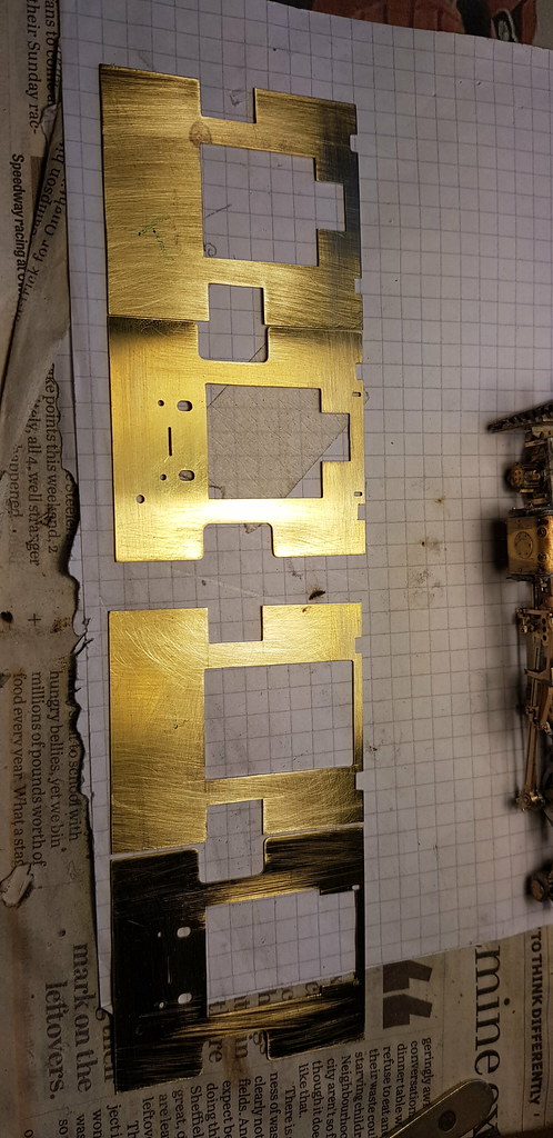
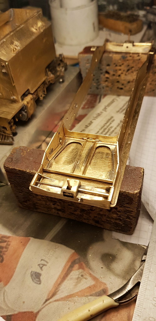
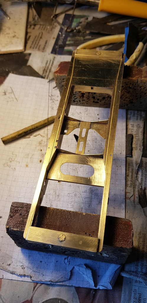
...and so on to the cradle. The platform etch is nothing like the real platform on 138. The frames (and their overlays) are actually quite accurate although the fold lines half etched into them are in the wrong place, also therefore the half etched lines in the bottom of the footplate are also wrong. I chatted online with a SAR modeller in Australia who offered to send some correct pattern chequer plate etched overlay for the top of the platform, so I decided to use etch upside down and modify it. The half etched lines would be hidden by the chequer plate overlay. I laminated the side frames and cut new fold lines in them in the correct place.
There was very little in the way of cradle frame stretchers in the kit and, like most garratts, they're on view! The kit etch for the footplate is too narrow on the inside. It extends too far towards the boiler and hides the fact that the kit has nothing between the frames. Below is a kind of step by step potter through everything I had to scratchbuild to make a decent representation of the cradle. (A bit annoying when you've spent a fair bit on a kit, but hey-ho it's fun...)
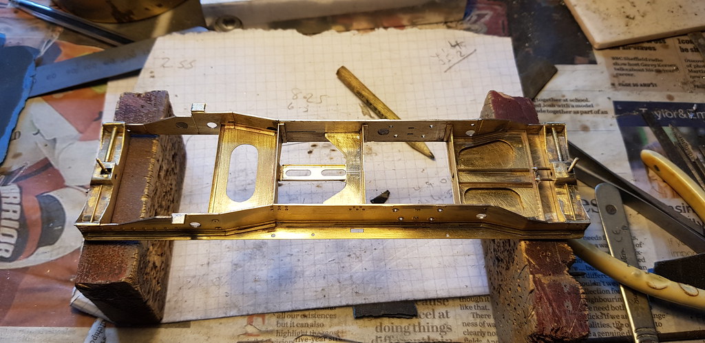
And lastly a bit of detail is attached. If you look very closely at the top pic on this post you'll see that the reversing rod linkage is half etched onto the frame plate. What were they thinking? We're not having that!
More details next...............
There was very little in the way of cradle frame stretchers in the kit and, like most garratts, they're on view! The kit etch for the footplate is too narrow on the inside. It extends too far towards the boiler and hides the fact that the kit has nothing between the frames. Below is a kind of step by step potter through everything I had to scratchbuild to make a decent representation of the cradle. (A bit annoying when you've spent a fair bit on a kit, but hey-ho it's fun...)
And lastly a bit of detail is attached. If you look very closely at the top pic on this post you'll see that the reversing rod linkage is half etched onto the frame plate. What were they thinking? We're not having that!
More details next...............
Nick Dunhill
Western Thunderer
...Quick update
Nick Dunhill
Western Thunderer
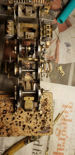
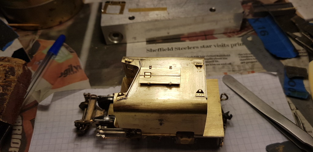
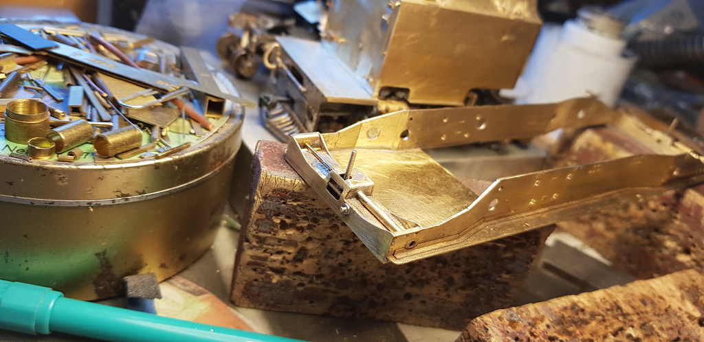
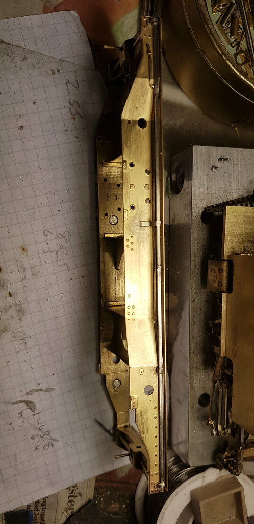
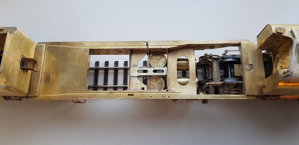
....I finally got round to finishing the plumbing for the injectors on the sides of the cradle and turned my attention to the brakes. I spent a day making small components for the brake system. I copied a picture of a garratt stripped down at Dinas and the 3rd pic is where I ended up.

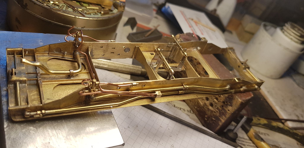
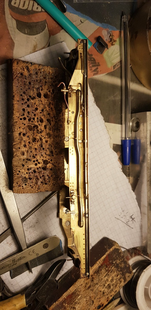
As you do, when flicking through lots of pics of 138 in action, I realised the original pic I had copied was of 87 and it had been modified and fitted with what looks like modern air brakes. To my dismay all the pics I was looking at of 138 had good old fashioned vacuum brakes. The next day I dismantled it all and rearranged it in the correct combinations for my chosen prototype, D'oh. How the days fly by. So here's the proper set up, brake system and hand brake mechanism. The brake cylinders are modified Griffin castings I think.
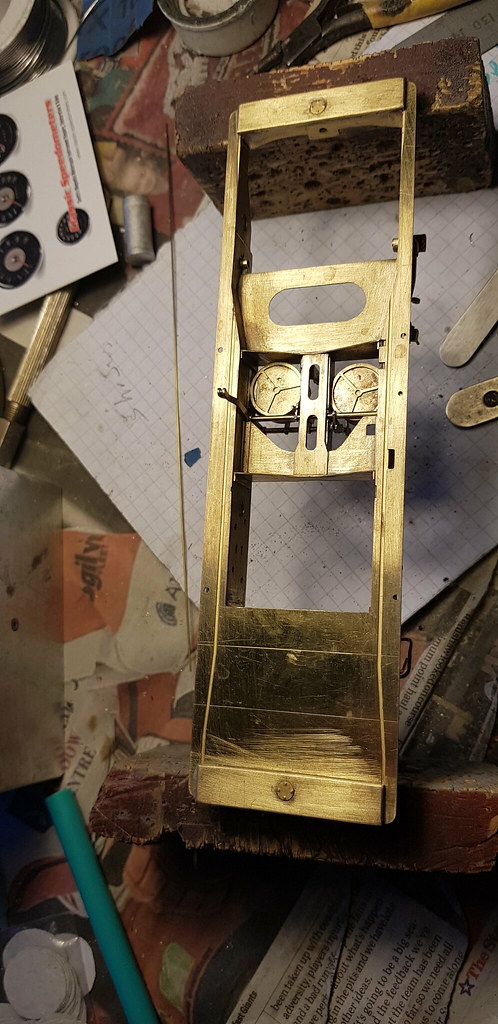
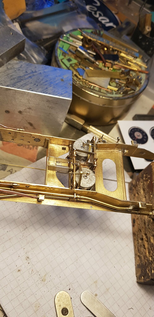
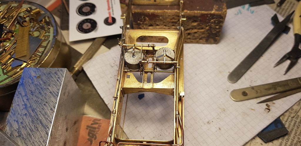
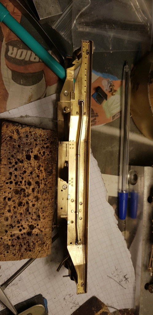
The assembly has now been cleaned up by scrubbing it with Viakal, some say I should do this step BEFORE taking pictures. Next I amuse myself by making air tanks from tube and plate and it takes hours, instead of the minutes it would have taken to make them from solid if I had a lathe.........
As you do, when flicking through lots of pics of 138 in action, I realised the original pic I had copied was of 87 and it had been modified and fitted with what looks like modern air brakes. To my dismay all the pics I was looking at of 138 had good old fashioned vacuum brakes. The next day I dismantled it all and rearranged it in the correct combinations for my chosen prototype, D'oh. How the days fly by. So here's the proper set up, brake system and hand brake mechanism. The brake cylinders are modified Griffin castings I think.
The assembly has now been cleaned up by scrubbing it with Viakal, some say I should do this step BEFORE taking pictures. Next I amuse myself by making air tanks from tube and plate and it takes hours, instead of the minutes it would have taken to make them from solid if I had a lathe.........
Nick Dunhill
Western Thunderer
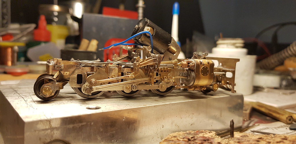
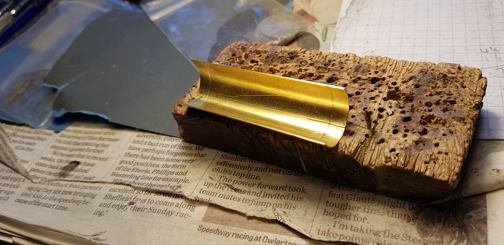
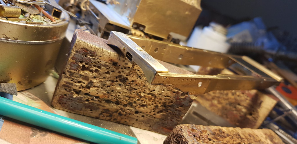
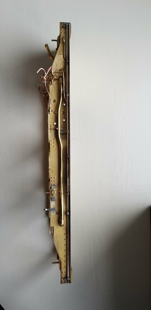
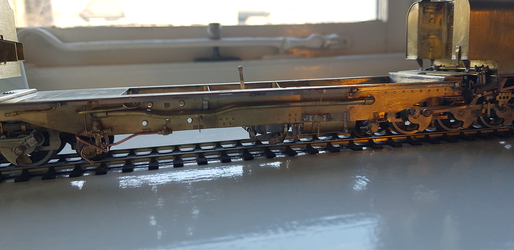
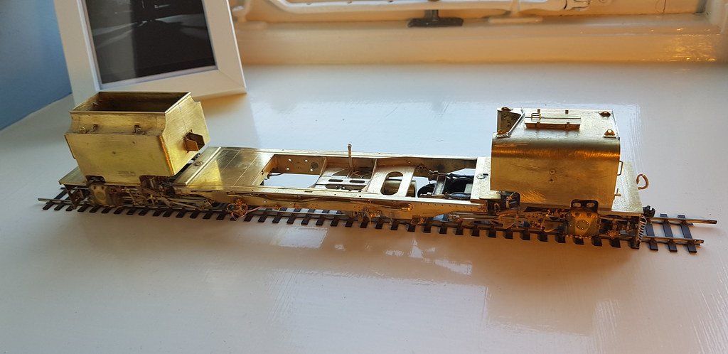
....a quick update, I made some vacuum reservoir tanks (thanks Paul!) from brass tube and sheet. It did take a while, but not as long as the fixing straps and saddles to mount them. Antway I'm on holiday at the moment so can't post any pictures of them, but you can see them suspended under the cradle in these pictures I took last week.
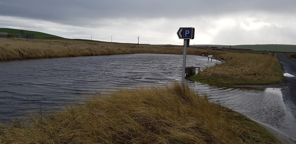
Had a bit of trouble parking at Skaill Beach today.
Next, loads of pipework......
Had a bit of trouble parking at Skaill Beach today.
Next, loads of pipework......