MS Programmes were never designed for large bitmaps, which is essentially what I was doing. As the file grew so did the speed at which the programme worked. A look at the activity on my pc assured me there was loads of spare memory and even processing power available but the programme was running so slowly it became almost impossible to use. Back to the drawing board.
I have now purchased from Tool Station 50m of galvanised steel banding. 1mm thick, 20 mm wide. This is slowly being cut up and laid down as the magnetic sub-base for the track, which will hopefully mean that any engine with magnets will be able to manage the SDJR gradients. At £27 for the reel this was a lot cheaper than DCC components metal sections. Plans have also been made, on Templot, for all the visible point work on the SDJR line.
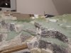
In December I promised my sons that the branch would be wired up and running for their delight at Christmas. Well I nearly made it, and then a baseboard joint that I was working on remodelling collapsed. (Some hidden additional track work meant that further holes needed to be made in the scenic profile board. At some point I removed the bolts and forgot to put them back. I did get as far as laying all the storage yards for my son, but had not cut through the track at the baseboard joint. I was just leaving for a cuppa as one board dropped. Rhubarb I muttered, or something like it..) The damage to the track and points was considerable.
I have now purchased from Tool Station 50m of galvanised steel banding. 1mm thick, 20 mm wide. This is slowly being cut up and laid down as the magnetic sub-base for the track, which will hopefully mean that any engine with magnets will be able to manage the SDJR gradients. At £27 for the reel this was a lot cheaper than DCC components metal sections. Plans have also been made, on Templot, for all the visible point work on the SDJR line.
In December I promised my sons that the branch would be wired up and running for their delight at Christmas. Well I nearly made it, and then a baseboard joint that I was working on remodelling collapsed. (Some hidden additional track work meant that further holes needed to be made in the scenic profile board. At some point I removed the bolts and forgot to put them back. I did get as far as laying all the storage yards for my son, but had not cut through the track at the baseboard joint. I was just leaving for a cuppa as one board dropped. Rhubarb I muttered, or something like it..) The damage to the track and points was considerable.