Hi,
A pair of Boilers
As I have built a boiler works there was a need to have some boilers - so I built a pair, using the empty 'energy drink' cans as a former for them.
The cans that I have used are 3.5 scale feet in diameter, and about 9 to10 scale feet long – perfect! Lager cans are much larger and could also be used. The youths, having drunk the contents, discard the now empty can onto the ground and thus they are everywhere, and a worthwhile number that I was going to use for my purpose, were checked to verify that they were are unmarked – I did not want bent or bashed ones! These were brought home, washed out and put to one side whilst I worked out what to do with them.
Another source of a tube of this approximate size, is the one used for the cartridge guns containing filler etc. They will need some extra end discs to close of the ends however., and are a bit thicker in thickness.
My boilers are described as ‘stationary boilers’ they generally, on the full size ones, have the three pieces of rolled boiler plate, the centre one is the inner one, with the end portions lapping over the edges of the centre part; all are riveted together. Locomotive style boilers were also used: these have a (very small) taper as the sections with the smallest diameter boiler sheet at the front and the other two lapped onto the top of the one in front. That will give a small taper; the largest diameter portion is therefore over the firebox, with its vertical sides. This style of boiler was used a lot for ‘portable’ engines which were the forerunners of the Traction Engine. Stationary boilers provided steam for machinery (don’t forget that I model before electricity was being used industrially). These boilers are generally fitted inside brick support walls, and above the area for the fire, the smoke from which ran through the tubes to heat the water, sometimes with a return (doubled back) flue..
Back to my boiler – the ‘energy drink’ cans that form the boiler are generally made from 4 thou aluminum sheet, which dents easily; so one can is cut apart (using a slitting saw or a cutting disc, and please protect your eyes when using these) the ends are discarded, and the tube cut down its length; I made a couple of discs from 3mm thick PVC solid foam; political or such signs are a good source for this thinner material) glue to the ends of the whole can: measure the can and its new ends, and divide it into three. Add a small amount to that and in the centre of the can add a wrapper; from the tube from the ‘cut apart can(s) ’ measure two more pieces to one third length, of the whole can, and cut them apart from the wrappers (for the can, now a tube, with a vertical slit down its length, using your modeling scissors. Before adding the wrappers to the ends I filled the depressions between the ends and the body of the can with filler – I used up some window frame sealant but anything will do; to assist in keeping it there I add a layer of glue and add the filler over it. Smooth off the filler when dry, and then the wrappers can be added, these are then glued over a still whole can). These measures make the can much stronger; it now has a centre wrapper – add to that another wrapper; with the first one I made this from heavy paper – it needed more work and some filler to smooth off the step that was the overlap for the supposed boiler wrapper; in Mark 2 I will use some .010 plasticard, and double the overlap with the rear edge being smoothed off when dry.
When dry the couple of pieces precut to 1/3rd of the can, plus ends, length can be added. These are glued to the ends of the can you already have, and make the end section quite strong, they go over the PVC ends and are flush with them, covering the filler. I used Evo-stik as a contact cement, letting it almost dry as the instructions, and then adding the two sections; there will be a small section left this should be at the bottom and can be filled with a small piece from another can. There will be a narrow section left – this can be filled with another small strip; make sure that this is at the bottom of the unit, and if required smooth off any rough edges.
Now for the difficult bits! The outer sections need covering with plasticard sheet – I used heavy paper for the centre one, as above – and had to do more work as a result; next time it will be 10 thou plasticard sheet in the centre; the ends are covered in pre-curved 20 thou sheet held on with Evo-stik epoxy glue with an overlap of about 8 – 9 mm it is not critical. The overlap can be glued to the under sheet with styrene glue. To ensure the overlap is well glued I lightly secure it in a vice holding down the overlap for about 1 hour, whilst the glue dries. Ignore the ends for now. My miniature rolling mills for the sheets are my fingers – start off against the edge of a table, and continue it with your fingers to sharpen the roll. Glue them in position, getting both ends even and with the overlap in the same position and on the opposite side from the centre wrapper – use a ruler to ensure all is correct, and that all are fixed the same way – I managed to do it wrong so some had to stripped off and done again!
Boilers have lots of rivets! Cambrian Models, who amongst other things make plastic rivet heads (no stalk – in cross section they are triangular, the ref number is NA7 and each sprue holds about 230 rivets; (link
http://cambrianmodels.co.uk/16intropage2.html) they can be glued down with plastic cement, they also make some plastic nuts and bolt heads. This quite small boiler has in excess of 300 on the horizontal seams these being double riveted – there could be up to 4 lines, on the larger and higher pressure boilers, on the seams between the plates – round the circumference they are a single line. The double lines are 4mm apart on each line with the upper ones stepped sideways by 2mm; the single lines are 3mm apart. Each rivet is lifted from the desk surface by a liquid cement charged brush after wiping some liquid cement where they are going – the (tiny) rivet will then in position ‘drop off’ the brush into its intended location. Do not take a lot off their sprue: about 10 or so at once is OK – they do have a habit of hiding or worse still flying off into the ‘wide blue yonder’, be careful cutting them off the sprue too heavily– I use a curved blade scalpel, with a gentle pressure, pulling the blade down the length of the sprue taking two or three at a time, and keep a couple of my fingers above them hopefully ensure they stay on the desk.
These boilers had 4 heavy fixing lugs; I made these from 1.5mm plasticard; one part curved to the boiler curve and another under the lower edge; a small brace fits on top and in the centre, each one has twelve fixing bolts made from 30 thou cubes. They are fitted just above the centerline of the boiler. These are what held the boiler to the brick walls that they would normally be fitted into; the walls were double brick (at least with the inner ones at a height that these lugs would fit onto; I am not sure how they fitted, as naturally boilers expand and contract, so there must have been some leeway in the fixings.
What about the ends? After the marathon ‘riveting’ of the sides (I am impressed by the work that the boilersmith’s did after the above, even more so as I can well imagine the noise produced, no wonder Boilersmith’s became deaf) I ‘chickened out’ on drilling the ends for tubes or just the ends (so holes) of them – I also did not trust myself to drill the holes close enough together with the material ripping between holes, and I was not going to make the ends in brass). So I decided that the ends had sunken tubeplates, and these needed some protection, that meant that the ends could have some (scrap) plank covers on them; the planks are from 1.5mm (approx. 1 scale inch) thick plasticard, with a couple of vertical pieces to hold them together; they are supposedly held in the tubes by bolts with an expanding nut and (soft) washer – they would not have any purpose other than protecting the ends; and they make locating the boiler, on its wagon ( flat car for rail transport) easier as well!
I originally fitted a central casting, which needless to say is plasticard and a bit of scrap tube, for a steam take off point. That was later moved to one end, and in the centre I fitted a small (made from a piece of scrap tube), steam dome, this is 17mm diameter and 17mmm high, there is a .020 plasticard base, and a doubled .020 plasticard top with another piece on top of that – supposedly for the steam take-off, or fitting safety valves – the original now is supposed to be for either a safety valve or water feed. Around the base and top are a couple of .015 plasticard (it was easier to curve than .020) strips, pre-curved and cemented in location these have tiny cubes of .030 square plasticard to replicate bolts. On one side there is a vertical line of rivets indicating the join, the total number of pieces in the steam dome is 53!
My first (yes I will make some more, of different sizes – this one is a small one), boiler is 5.5 inches long (say 9 feet scale) and just over 2 inches diameter say 3.5 scale feet.
The second one was started being mark2; this one does use an (empty) Red Bull can; the centre had a wrapper of .010 plasticard, with a doubled overlap, add an extra overlap piece to make the thickness up to .020 the same as the outer ones, where the rivets will fit. This is quite thin and Evo-stik can make the plasticard partially melt so spread the glue, and leave it to be almost dry as the instructions. Make sure that you have them both the same way – I didn’t and it had to come off!
This boiler is just under 6.5 inches long and a scale length of 10.75 feet, with virtually the same diameter. The basic construction is as Mark 1 with more rivets as it is larger, and it has a much larger steam dome – its new owners must use a lot of steam. The planks on the ends are slightly higher, I added and extra and smaller plank. I have painted this boiler a darker colour for some variety; the colour is listed as ‘Indian Red’.
The domes could have the steam outlet on the side of the dome, and the safety valves fitted to the top. My steam dome is a part of a menthol crystals container; cut to length and roughly shaped at the bottom with a sanding drum, finished off with pulling it backwards and forwards over a piece of sandpaper wrapped round the boiler, this is quite a deep section of a circle as the boiler is a small diameter so it will take a time. The top of the steam dome is a layer of 3mm PVC with the edge rounded off, it will then have some .020 discs of access points to the dome, and a larger disc for the base and the strips top and bottom as the previous one. These have the rivets made from tiny cubes of .030 square rod, again applied with the point of a liquid cement charged brush, onto the plasticard which has another layer of the glue – that makes the cubes ‘sit down’ and come off the brush tip.
The water inlet location is towards one end of the boiler, and the other end has a ‘manhole’ – this one is quite small (as is the boiler) and allows access to the interior of the boiler (I presume by a hose?). The outer shape is an ellipse and the fixing arch is made from a piece of .060 plasticard with a couple of bits of rod as well, more .030 cubes for rivet heads are fitted around the ellipse. Two much smaller mud holes have been fitted which are where the mud and scale would be flushed out. The shape for both ellipses’ came from a template I have from my drawing days, and that was a long time ago!
Mark 2 has a different style of fixings for the boiler; these are the style that has the boiler hanging from wrought iron rods that are descending from cross beams above it. The boiler fixings are made from a couple of pieces of .060 with a couple of .020 washers where the bolts to the ends of the rods (forged double pieces at the lower end of the rod, these slot over the piece on the boiler) fit; the upper end has a couple of large nuts with a large washer/plate beneath them – they rest in the slot between two ‘U’ shaped beams fixed with a slot between them. When dry they were drilled with a drill 1.6 diameter – first use a smaller one then enlarge it by hand, the rivets on the bedplate are again .030 cubes.
The collection of planks on the ends are painted various shades of brown over a stone colour undercoat, to indicate the ‘scrap’ assembly of them, being for a temporary purpose,
When painted a pencil is run along the joins to enhance the edges and cover up any overpainting that has gone too far! Finally add the fixing nails, to the vertical pieces of ‘wood’ – small dots added with a pen, and to blend everything together and kill the metallic shine on those pencil lines, varnish the ends. I have added some placards with the name of my boiler shop indicating them as the builders – these were also varnished over when dry, for protection and to ensure the stay in position, they were glued on but the varnish will keep the edges down.
I also made a new flatcar for them, and also a horse drawn boiler wagon.
Here are some photos -

Mark one boiler in progress

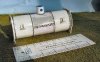
Mark one boiler almost ready for painting, with lots of the Cambrian rivets!

Mark 2 in the same condition.

painted and on the flatcar, with some crates for the ancillaries.

One of the boilers on the scratch built boiler wagon for alternative transport. The labels on the side are the work of the computer. There are a couple of horses with a mule in front; mules are much better animals for leading as horses can be 'spooked'.

A close up of the boiler wagon which is basically an enlargement of the drop centre dray wagon for carrying barrels.
Yours Peter