Bottom Works Sidings - An industrial what if.

ChrisM

Active Member
Hello everybody,

Hopefully you don’t mind me jumping straight in here, rather than heading through the new members section, but it made sense to keep everything in one place... so by way of an introduction, I’m Chris, half of the double act that put together the various bodgings that appear on otcm.wordpress.com

Despite never having previously posted on WT, I’ve been a lurker for a couple of years and wanted to share progress on my cameo competition entry through the forum, it feeling the best and easiest place to get feedback and take other people’s ideas on board to hopefully improve the final outcome. I planned on making the first post in November last year so am running a little late on the initial update - I’ve actually been trying to maximise time on the layout with some ‘little and often modelling’ rather than looking at forums hence not getting round to it...

I’ve spent the last 5 or so years in a bit of a layout drought, not having actually produced something single handedly since my mid teens - looking to move out my parents house and not knowing what space would be available for a layout essentially put layouts on the back burner although I spent plenty of time working on rolling stock. Myself and Oly then built Stoating Bank in a bit of a rush, and took it out to a few shows, but since then, despite now knowing what space I have and several false starts nothing has really appeared. The announcement of this competition, complete with deadline, seemed the ideal opportunity to get myself in gear and actually build something!

Now, onto the layout - from the outset I wanted the layout to be a little different, portraying a run down industrial scene in an early 1970’s winter. If possible the industrial railway would be supplemented by some BR action, but only if it didn’t result in things looking too cramped or too much compromise. This concept developed into an early plan for a small set of interchange sidings half way along an industrial line, with a couple of sidings serving various steel works buildings. A scale plan of this proved it fitted although somewhat cramped, into the 5ft space I had given myself to work in.

The only flaw with this was that upon measuring the car just prior to constructing the boards, it became obvious only a 4ft 6in board would fit, and as such the baseboard was built to this size - I certainly didn’t want to go down the van hire route for something no more than 10ft in total length, and this seemed to undermine the cameo concept somehow. Putting the plan onto the shortened board did not work at all, and it was back to the drawing board for a rethink.

Several ideas, geographical locations and plans later I finally found something I was happy with and seemed to offer sufficient operating potential. This is key to me getting any enjoyment out of operating, every movement must have a purpose and be carried out in a prototypical manner - you can’t run a ‘coal train’, but you can run 8M27, the 13.27 loaded coal from A to B.

The original plan had gone under the working title of ‘Bottom Works’, representing the lower half of a steelworks complex, and identifying the layout, hopefully, as being set in Yorkshire. I was keen to keep this name going but as the new plan no longer featured any works buildings (a cameo sized baseboard fills pretty quickly when steelworks buildings are on the agenda!) I added sidings to the name, what is modelled supposedly being the one time junction for a line serving a plant at a lower level.

I think the finished plan is a bit of a cross between a layout in its own right and a ‘bitsa’ - while it doesn’t try to portray a small part of a larger scene, it is totally reliant on the imaginary scene around it to work, so what am I modelling?

Towards the rear of the layout there is a freight only branch running from a set of exchange sidings to a small steel processing plant (the exact specification of this and the traffic it creates is still TBC...) This is maintained and operated by BR, with BSC movements having running powers. Mid way along the layout this connects with a BSC internal railway system serving a secondary entrance to a coking plant (assumed to have originally been part of the steel companies property portfolio) and there are a couple of loops for the interchange and holding of traffic. There are then a couple of sidings and a lifted line, formerly heading off to the previously mentioned Bottom Works (another area of the former steelworks). The whole concept is heavily inspired by the Stocksbridge Railway. Hopefully this overhead shot from before too much had happened gives an idea of the plan:

image3.jpeg


There is nothing special about the construction methods, the boards are a mixture of 6mm and 9mm ply - I’m certainly not a carpenter and as such the boards are a long way from perfect, but will hopefully do the job. (I didn’t want to end up restricted by the constraints of an off the shelf kit board, and was keen to follow the advice of Iain in the book with all the board components built in from the start.) In hindsight I wish there was a bit more 9mm in it for some added strength, but it is nice and lightweight... the lighting pelmet is removable at present to ease construction but is intended to be semi permanently attached upon completion - at present, my initial experiments with LED lighting haven’t convinced me this is the way to go and I may install a fluorescent tube if I don’t have any more luck, but we will see.

A nice cold day for Oly and myself in November was spent putting this together...
image1.jpeg


image2.jpeg


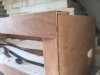
A bit more work and the front facia cut to shape - someone stole a chunk out of the front!!

image4.jpeg


Experiments with the lighting...
image5.jpeg

image6.jpeg


To provide a little vertical relief below rail level, I added a raised trackbed from ply, which has also helped strengthen the board a bit (too much 6mm ply remember!) and 5mm foamboard, then removed a small section of the solid top to create room for a minor stream to appear out of a culvert. This also means there is a minor but noticeable variation in height between the sidings at the front and rear, which makes a big difference in my opinion.

I’ve built the pointwork up from copperclad and code 75 BH Rail - I wanted to ensure the trackplan flowed through the layout and there were no lines running in straight lines parallel to the board edge. It’s intended that the left hand fiddle Yard will be cassettes whereas the right hand end will be a small loco release traverser.

image9.jpeg
image8.jpeg
image7.jpeg


Thats about as far as things have got so far, I'll soon be setting too on the topography with plenty of papier mache or filler, and have already started putting a few scenic features in place, such as this groove where a stream will descend a set of steps to reach the culvert that will pass under all lines.
image11.jpeg


I’ll leave it at that for now, in a future post I’ll cover the lines historical and geographical context in more detail (it's far too long to fit here!) as well as posting up plenty of progress updates.

I wonder if this will be the last cameo layout to appear out of the woodwork on here...!


Cheers
Chris
 

Attachments

  • image10.jpeg
    image10.jpeg
    87.1 KB · Views: 350

ChrisM

Active Member
Evening all,

A good days progress today has seen a number of jobs done and a start on track laying - although the boring things took longer than I initially anticipated, it feels like I've made a big step forward...

First up I finished the points by adding tie bars, I had utilised a couple of spare half hours in the week to get the sleepers gapped, so just some filling to go.

The tie bars are a bit coarse but should hopefully be robust. In future on a 'mainline' layout I'll look into moving the tie bar under the baseboard I think, but here they will be pretty buried among the muck at track level

image3.jpeg


Next up, and keeping the soldering iron warm it was out with the wire to start adding droppers to the underside of the rail prior to installation. Nothing complex here, the layout will be DCC operated so a wire to every rail and one to the point V's (in a noticeably different colour to pass my idiots guide to wiring things up the wrong way) is all that is needed...

image1.jpeg


image2.jpeg


With the two main points in place, it was onto the plain track which is C&L flexi. I have however modified this by removing the webbing, hopefully worth the effort, especially since the ballast is intended to be less than perfect in the yard. I can now spend the next couple of months recovering small bits of black plastic which have fired into every corner of the loft room!!

So far I've only managed to get the three main sidings down, held in place with a thin layer of Tommy Walsh's finest quality Poundland PVA (which is actually pretty decent I find). This will obviously be strengthened when ballasting commences.

image6.jpeg


image4.jpeg


As there was some track on the layout it seemed excusable to pose one of the locos intended for this project; she is just waiting on couplings and some Laserglaze to bring her up to the same standards as her sister, number 35:

image7.jpeg


Cheers.
Chris.
 

ChrisM

Active Member
Well there hasn't been a huge amount of progress since the last update, a busy couple of weeks have got in the way - we are also having a new boiler fitted which has meant moving the layout from its usual home to make space for this to happen.

I did however get an opportunity to sit in the garden and do a bit of weathering on some of the rather lovely new Accurascale 24.5T hoppers, which will ultimately end up on the layout bringing in raw materials.

image4.jpeg


There are some more photos and a more detailed write up/review over on the blog:

Thank You, Accurascale

Cheers
Chris
 

ChrisM

Active Member
Apologies for the fact I’ve been a bit slap dash with providing any updates over the last couple of weeks… A pretty hectic schedule has meant that what spare time I have had has been spent modelling rather than writing updates to go online!


When I first built the baseboards, I went for a very lightweight design, and followed the Rice ‘monocoque’ principles touched on in the book with the front, end and rear boards forming part of the frame and therefore being integral to the baseboard, rather than being added onto a self-contained board. However, I’m definitely not overly skilled when it comes to woodwork and with much of the board being made from 6mm ply I had decided that things were a bit too flexible and wanted to add some strengthening before going much further – in future I’ll use much more 9mm from the outset to minimise the amount of extra framing required, but this was a good opportunity to experiment on a self-contained baseboard and see how light things could be.


Anyway, last weekend I had the first opportunity in ages to get the baseboard outside and do the necessary woodwork to sort things out. As it turned out to be a lovely sunny day this also involved getting sunburnt but I guess that is all part of the experience! BWS now sports some additional diagonal framing between the already diagonal cross members to offer some more support, and the facia has been improved upon with some new woodwork to the rear ensuring all is held together tightly. While I was at it, I got the hole saw out and went a bit mad chopping bits out of the framework, deciding that I should keep weight to a minimum – I think this was a worthwhile exercise, and it has made it look vaguely professional underneath… (looking and being are both very different things!)

image2.jpeg

image3.jpeg

New front strengtheners being added...

image4.jpeg

That vulnerable bit of polystyrene has been protected

image6.jpeg

image7.jpeg

New undersides in place!

image5.jpeg

Mega weight saving!


Track laying has continued on the front sidings, with now just the kickback to install – this will be laid in code 55 flat bottom rail as it is supposedly the stub of a long since lifted line, and to create a bit of a talking point.


I’ve also had a chance to get some papier-mache onto the polystyrene formers for the landscape, which I didn’t find particularly satisfying – in future I will revert to a layer of filler as I have always used before I think, but, as I said earlier this is a good opportunity to experiment with 'new' (well since primary school!) techniques. While I was doing this I was struggling to get things to look natural and as a result the stream running across the layout has been filled in as it did not work with the flow of the landscape, I am much more comfortable with how it looks now although a little further work with mocking up some landscape is required I think before things are finished off.

image8.jpeg


Finally, while the layout was outside, I took the opportunity to get a first layer of black paint on the frame – this will need a second coat to finish it at the end but I have found it makes a massive difference to the appearance of things and should help to be able to visualise how things will look as the scenery is installed.

image10.jpeg


That’s about it for now, I don’t expect many huge strides forward progress wise over the next couple of weeks due to a busy diary but now have everything in stock to get on with the wiring so this will inevitably be the next job on the list, as well as getting a backscene in place.

Cheers
Chris
 

ChrisM

Active Member
I had been planning on using LED strips to light the layout, and to this end had purchased both blue and cold white strips to experiment with. However I’ve not been able to get a balance I am happy with, most giving a lighting tone far too intense for what I want to represent a cold overcast winters morning in Yorkshire...

Therefore, in a slightly retro step, I’ve invested in one of these:
745F111D-E940-4D29-963A-CE208009FFFD.jpeg

Which is now fitted behind the pelmet and wired up - being a low wattage this gives a far more balanced light over the layout and I feel much more comfortable with the results.... here are the old LED’s being pulled out in favour of the new strip light:

DFB8E3B2-3CAA-4D98-8F0C-BC75C151421A.jpeg


In other news, I’ve not been entirely convinced with the landscape on the layout as it stands, things don’t look entirely natural in my mind. Last weekend I tied down a prototype location that worked operationally, theoretically and geographically for which some of the existing scenery doesn’t really fit - as a result I am looking at making some amendments to the look of the layout and flattening it out a bit, which will hopefully be for the better - a small step backwards but hopefully a major leap forward!
 

Alan

Western Thunderer
Interesting comment about LED strips, I am hoping to use them on Louville Lane. To be fair it is meant to be summer at the lane done in the South West, so hopefully a more intense light will look more natural.
I hope your amendments to scenery go well.
 

ChrisM

Active Member
Hi Alan,

The lighting I achieved when using them was quite harsh and would have been perfect for a snowy day, but I have quite a clear picture in my head of how I want it to look and somehow it wasn't quite 'right'. I could have tried some warm white LED's but decided to go for a strip instead on the basis it's tried and tested!

I will however experiment with using a blue strip tucked up behind the fluorescent strip to see if this has the potential to add some interesting lighting effects.

I've seen a combination of warm and cold white LED's used very successfully for bright summers days so reckon you'll be just fine!

Chris
 

76043

Western Thunderer
Hi Chris, On LED diffusion, it is possible to make a diffuser with tracing paper or similar, mounted on a frame at a distance from the LEDs that provides the diffusion you require. I would think a distance of 1-3 cm would be enough.
Best regards
Tony
 

Simpas

Western Thunderer
Alan, I'm contemplating some form of diffuser using greaseproof paper from her ladyship's kitchen because it's there and I can get my hands on it. One layout I saw in Perth at a 2mm 'do' had such a diffuser simply sellotaped over the LEDs. Did the job.

Mick S.
 

ChrisM

Active Member
Thanks for the suggestion Tony and Mick, I'd not thought of something so simple as a solution, although thinking about it now it makes complete sense. I may have a play with this at some point even round the softer light from the strip if I think things need toning down a bit more...!

I'll have to keep an eye out at shows for anyone else using his technique, I've not some across it yet!
 

ChrisM

Active Member
I should probably apologise for the lack of an update in the last month and a bit, I have however been cracking on with layout construction integration spare time I've had, and managed to make significant progress in my mind from the last set of photos...

I left the last post with a comment I was proposing to amend the scenery and remove some of the hills... so it was that one evening I attacked my nice landscaping and removed most of it! Do I regret this rash decision? Not one bit! The look of the layout has been transformed and looks far more natural in my mind, representing a landscape that is completely unremarkable, and that will hopefully fit in much better with my proposed semi industrial scenery.

image2.jpeg


As part of this, I've added a roadway to the rear of the layout, which has principally been made from MRJ envelope cardboard - a frame being built up as a set of foundations and then the road bed being added on top as suggested by Gordon Gravett. Although I intend this to be no more than a loose ash road, I took care to add a slight camber and then spend a considerable amount of time smoothing the curves and gradient changes out with filler, the end result I am pleased with so far.

image4.jpeg

image3.jpeg

image9.jpeg

image10.jpeg


I intend this road to serve a small crew room alongside the loops, and with an assumed fairly gentle pace of life on the line this will provide some extra movements as the loco runs over and sits outside while the crew have a brew... an idea pinched straight from Hywel Thomas' Morfa Bank Sidings!

You can probably also see from the above the back scene has appeared, this will however be changing colour shortly as I am not satisfied with the shade!

image5.jpeg

image6.jpeg


At the front of the layout there is a coal yard going in where once there was a Hill - now an effect of making things a lot flatter is the difficulty in blocking view lines to the holes in the backscene. I think through a combination of a building, a stack of coal, a wagon and a couple of bits of industrial detritus I have managed to cover the left hand end, but we need to get a bit further to confirm things....

image8.jpeg


The siding that serves this coal yard is planned to be little used, is steeply graded and in a pretty poor state of repair, the sleepers buried in muck. To help this impression on its way, I've layed the siding in code 55 FB rail which will hopefully be quite effective.

image11.jpeg

image12.jpeg


All the scenery is now covered in a hard shell with a base coat of paint and things are starting to look a lot more complete. Now that the weather in the south east has cooled down a bit, the next job is to get everything wired up and working, then carry out some thorough testing. The thought of a session in the loft with a soldering iron in the recent heatwave was a bit off putting hence the progress above ground level! I have however done a very rough and ready test piece which has been deemed a success and the technique will be developed in practice somewhat more neatly!

image1.jpeg


Cheers
Chris
 

Simpas

Western Thunderer
Chris,

Quick update re the diffuser.
Just prior to going to Wells (i.e. the night before) I installed the greaseproof paper but it diffused the light too much so I abandoned it. Also because my little effort has a mere 1/2 inch (12mm) depth to the top of the 'arch' it is still possible to see the individual LEDs through the paper. I'm not saying don't do it but use more LEDs and have a greater distance between where they are mounted and the diffuser.

Mick S.
 

ChrisM

Active Member
Thanks Mick - I've got the strip light in place now with its diffuser fitted but to be honest there is probably potential for it to be diffused a bit further in my eyes... it might be worth a go, the worst that can happen is that I don't like it and take it back off again!

Cheers
Chris
 

ChrisM

Active Member
Hi All,

There hasn’t been a huge amount of visible progress above the baseboards since my last post – things are now at the stage where I can’t really go any further until I’ve finished wiring and been able to give the layout a full shakedown and simulated exhibition operating session to try and identify any issues that need ironing out before I set the track permanently in place.

I have, therefore, been busy with the soldering iron and glue gun under the baseboard wiring things up – so far I have put the main bus wire in, which uses sections of copperclad strip glued to the underside of the board in appropriate places linked together and to the controller, and am running wires to the switches that have now been mounted in the left hand facia panel.

image1.jpeg


image5.jpeg


image2.jpeg


Point control will be by way of servos, I was going to go with Tortoise motors but as I has a selection of bases and servos already in stock that had been intended for a previous project it seemed a logical way to go, especially as I’d need the control board for signals anyway. The bases came from the States a few years ago (back before servo control had taken off here), I think they were from Motrak Models, and are lovely and simple!

image4.jpeg


A Megapoints controller has also been purchased and I am in the process of mounting and wiring this.

image3.jpeg


I’m hopeful I will get all the wiring in place and the layout up and running in the next couple of weeks, it will be good to get some trains running at last!

As a side project I've started work on one of the ancient Dapol JCB kits - this is something ideal for me to work on when I'm not in the loft but still layout related! The plan is that this will be super detailed and work in the coal yard at the front left of the layout... looking at some prototype photos I've got a fair amount of work to do to get it to the standard I envisage! In my eyes this is still a better starting point than the new Oxford offering, the fully poseable features on the latter somewhat detracting from the overall model in my eyes...

image4.jpeg

image5.jpeg


Cheers

Chris
 

ChrisM

Active Member
Hi All,

Probably about time for a bit of an update!

Although not much has changed on the scenic section (and as such there hasn’t been much exciting stuff to write about) I’ve been doing a bit here and there under the baseboards, the end result of which is that the wiring is now essentially complete and the layout is working! Servos are also mounted for point control so I’ve been setting this up, which I think I now more or less have the hang of... under the boards therefore now look like this:

364BEF83-0DE1-4E61-98A3-544CA343B412.jpeg


9DB5464E-2DAC-4CCE-9CF3-BB1ABD9C67B5.jpeg


The servo cables not connected to anything at present are in place ready to be hooked up to the signals, which Mark Tatlow very kindly volunteered himself to build (before realising what I wanted!) - having seen some photos though they will be the best bit of the whole layout...

At the weekend I finally got the opportunity to get the stoarage yards at each end sorted, a job I’ve been putting off for ages. Inspired by my friend Andy Jones’ solution to supporting the pelmet on his ‘Tarring Neville’ layout, and Mr Rice’s comments in the book, I thought I’d try a suspension method rather than a leg for support, therefore providing more flexibility with display height, as the scenic section sits on adjustable legs.

I’ve used a metal wire kit which comes with everything required, and mounted it so that the stoarage yard hooks onto the top of the layout structure. The hook is adjustable so once in place can be tightened to the correct tension.

0AFA4959-8976-4814-9199-DCD732401D33.jpeg


The left hand storage yard seen above is a very simple affair. No wiring is in place as this will be cassettes and they overlap onto the main board, again as per the suggestions in the book. I need to do a little more sanding across the board joint and build some cassettes but otherwise that was a nice quick win!

C4E35864-E80B-4E2D-A459-E0F67EC3F205.jpeg


At the other end things are a little more complex, with the 3 loops on the scenic section ending in a sector plate for loco release. Now that the board is mounted to the scenic section I now need to paint the yards before I can start work on laying the track here, then I’ll be in a position to have a proper shakedown operationally prior to starting any scenic work that goes near the track!
D7539805-09F4-4443-8BD8-EE315EC7BE78.jpeg
7537068B-0354-4972-92BF-7562EA21F465.jpeg


Cheers
Chris
 

Simpas

Western Thunderer
Chris,

Everything is looking nice and neat. I like the simplicity of the suspension fiddle but not had the opportunity to try it in 2mil yet...!

Mick S.
 

ChrisM

Active Member
Thanks Mick, I expect for a small size 2mm layout, you'd barely need any form of suspension, but it would probably work quite well for a medium sized layout!

Not sure how long you could realistically make the suspended board while keeping the anchor point within the layouts main structure - I think if you went much more than 3ft you'd need to start looking at quite a complicated and ungainly setup...

Chris
 

ChrisM

Active Member
I think I've said before that I feel a plausible back history is key to the development of a layout, allowing the development of likely train formations and operations. So, with apologies for the wordy post, here we go:

Small scale iron working had been taking place in the area surrounding Elsecar and Wombwell, to the South of Barnsley, throughout the first half of the 19th century. These works were supported by numerous local coal mines, and were able to increase production with the opening of the Dearne and Dove Canal in 1804, its branch to Elsecar opening up vital trade routes. Development of the rail network in the area started in 1840 with the opening of the North Midland Railway’s line to Barnsley, followed by the South Yorkshire Railway’s route to the same town via the Dearne Valley, running alongside the canal. 1850 saw the opening of the SYR’s Elsecar branch, serving many of the same pits as the canal branch, further enhancing the areas industrial output.


Amongst the most important players in the area’s iron working business were Messrs Broadholme and Tait, who owned Beech House Ironworks situated on the banks of the Elsecar Canal just South of Wombwell. Their enterprise had expanded considerably with the opening of the canal, dispatching finished products over a significant area. These gentlemen were quick to identify the benefits the railway could bring and as such were frustrated when the North Midland Railway passed their works closely but significantly higher up the valley. Plans were filed with parliament to build a new rope worked incline from sidings alongside the North Midland at Wombwell station, down the hill and into the works, but before any work was commenced the South Yorkshire Railway was under construction and an easier level route to the new line was instead chosen, allowing the use of locomotives rather than rope haulage, thus significantly simplifying the export of goods to points Eastwards, including Doncaster and the River Trent at Keadby for onwards transport. The SYR opened their own branch to Elsecar shortly after this, running along the opposite bank of the canal branch, serving a number of local collieries which were also able to significantly expand.


The opening of the route West from Barnsley to Penistone opened up considerable new traffic potential to Manchester via Woodhead, and the works grew rapidly, soon filling the available site. With the availability of stronger locomotives, Tait (Broadholme had passed away by this point) oversaw the construction of the originally proposed line to Wombwell station on what was now the Midland Railway, only on a slightly different alignment, removing the need for rope working, and putting the company in a better position to haggle down haulage prices between the Midland and Manchester, Sheffield and Lincoln Railway as the SYR had now become.


As the works had expanded and production had increased, the need for coke had exceeded the capacity that could be constructed on site, and increasing amounts were being brought in from other coking works in the area, particularly that at Manvers Main. Tait, unhappy with this situation was keen to develop his own coking facilities, but, constrained by the site, was forced to build his works at a separate site alongside the MSLR at Wombwell, connected to the works by his branch line. At around the same time, in a drive to improve the efficiency of operation, agreement was reached for the MSLR to purchase the branch line from the main line to the sidings at the works gate, and a basic workman’s service was introduced to serve the works. Arrangements were, however, put in place to allow works trains to run over the line from the coke works on internal moves, the MSLR handling import and export traffic only.


The works enjoyed a healthy existence through the early years of the 20th century, the Great War putting unprecedented demand on its output. 1920 saw the closure of the canal branch to Elsecar and Tait’s son, who had by now taken over the running of the world from his father, was quick to take advantage, a new branch line being opened across the former canal into Cortonwood Colliery allowing direct delivery of high grade coking coal to the coking plant for the first time. This had previously been blocked by the Canal company, meaning the MSLR had to be used to get the coal to the works.


The 1930’s saw the works amalgamate and ownership change to the United Steel Company’s, along with a number of other works in the South Yorkshire area. Following nationalisation of the steel industry, this became part of British Steel and in the mid 1960’s a program of investment and rationalisation saw the installation of a new electric arc furnace at the works, replacing the blast furnace that was approaching life expiry. Production from this was supplemented by billets transported to site from other steelworks by British Railways, much coming from Rotherham and Scunthorpe via the former SYR Route. British Steel kept the coking plant open, supplying coke for other sites in the area, as this was still deemed to have a considerable life expectancy.


Further rationalisation of the industry saw the coke ovens shut down in the late 1970’s, followed by the removal of the furnace in 1980 as the Thatcher administration started to make its presence felt on South Yorkshire’s heavy industry. Closure of the route west via Woodhead in 1981 left what remained as a difficult to access inefficient rolling mill and the recession of the early 1980’s, coupled with a slump in world steel prices signed the final death warrant for the works, production ending in 1983, just one year before many of the local collieries wound their last coal. This brought to an end over a century of heavy industry in the area, most of the cleared sites sitting dormant for years before redevelopment as offices and shopping centres in the new millennium.

As part of this I've drawn the line onto a period map, to give an accurate idea as to the location:
image2.jpeg

The line curving across the lower left of the map is the Midland line through Wombwell station, Hill that diagonally crossing the top of the map is the GCR line through Wombwell Central station.

image3.jpeg

A close up of the coke works section of the map, with the small section portrayed on the layout hopefully visible.

Finally, I've been busy this weekend working on the fiddleyard, and have got the track down, next up is wiring!

image1.jpeg


Cheers
Chris
 
Top