4mm Brassmasters Rebuilt Royal Scot, 46109

Dave Holt

Western Thunderer
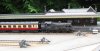
The inner chassis has been rebuilt to face the correct way round and proof of the effectiveness of the rebuild is shown in the photo below.
More crucially, it shows that the Lanarkshire Models inner chassis has been successfully married up to the Brassmasters footplate and outer chassis. This was the main issue to resolve in the whole tender construction. The LMS inner chassis is really designed to fit the Bachmann RTR Stanier tender, where it fits directly under the tender footplate. The Brassmasters tender has the body, outer chassis and inner chassis as three separate units, held together with screws through three layers. To accommodate the LMS inner chassis, the top of the outer chassis has had to be cut away at each end, to allow the inner chassis to pass through, and will be soldered to the underside of the footplate, in effect becoming a permanent part of the body.
One new fixing screw position has had to be made in the footplate and a couple of dowel pins accurately locate the inner chassis relative to the footplate.
Scot_204.JPG
I can now either complete the LMS inner chassis or assemble the inner body of the Brassmasters kit. Choices, choices!
Dave.
 

Dave Holt

Western Thunderer
In the end, I opted to complete the inner chassis before thinking about the body.
Unless I've missed something, the inner chassis is now finished, ready for painting. Here it is from two viewpoints. I've just noticed that I've fed one of the CSB spring wires through the wrong hole in the LH middle axlebox tail, so that wheel is riding high. Easily corrected but it just shows how careful one needs to be on final assembly.
Scot_205.JPG

Scot_206.JPG

Here, the footplate has been attached and the outer chassis frames loosely placed. At the moment, it has a slight tendency to lift away from the footplate, hence holding the front end in the following shot.
Scot_207.JPG
Dave.
 

Dave Holt

Western Thunderer
Just seen Mickoo's latest update which has reminded me that there are still the train vacuum and steam heating pipes to make and fit to the inner chassis - after the hoses/stand pipe have been fixed to the rear buffer beam.
Dave.
 

Dave Holt

Western Thunderer
Progress has slowed recently as I've been advised that sitting hunched over the workbench for long periods is exacerbating a lower back and hip problem that has developed in the last month or so.
Nevertheless, some progress has been made on the tender since the last posting. The rivetted overlays and much of the body detail has been completed leaving some further work on the front platform and the axlebox/springs to add to the outer frames. The following photos show the current state.
Side view:
Scot_211.JPG
Rear: I had an internal debate about the arrangement of data plates on the back and concluded that the tender allocated to 46109 in my period of interest probably had three plates covering number, building works and capacity. Some Stanier tenders only had two plates.
Scot_212.JPG

Front: Again I've made an educated(?) guess at the arrangements for the front platform. Scots had a higher cab footplate than many Stanier locos and their tenders had to have a higher platform, to suit. Some tenders, including those with the two preserved locos, were built with a high platform, but others, including mine, were modified from standard tenders by adding an extension to the platform. In side views, the original platform top plate can be clearly seen with the added part above. What I haven't been able to determine is whether the original top plate was left in tact or if the central portion was cut away. Arbitrarily, I decided to build the original platform and add a new portion on top, complete with intermediate support gussets, directly above the original ones below the original platform. Right or wrong, that's how in now is.
Scot_213.JPG

Dave.
 

Dave Holt

Western Thunderer
A trial set up behind the loco (which I know is sitting a bit low on its springs) showed the raised tender platform to be too high. Scaling from a good, side on photo, confirmed that the extension was too tall compared with the original platform height.
Luckily, it proved not to be too difficult to un-solder and reduce the height of the extension part.
The lowered platform has now been re-attached and so I'm back where I was 24 hours ago, but with a better representation.
Scot_214.JPG
Dave.
 

Dave Holt

Western Thunderer
OK, some of us (me) are more easily distracted than others (I'm sure there are some out there). Anyway, instead of completing the tender front platform, I decided to dabble with the drawbar and intermediate buffing arrangements. The drawbar pin has been made from two shorted 2 mm pinpoint bearings - the upper fixed to the chassis, with a deduced diameter 14 BA nut soldered in and the lower loose with a 14 BA countersunk screw to hold it in place. The intermediate rubbing block had been filed up from 1.5 mm thick brass strip and has been fixed to the front drag beam above the drawbar. This, together with its matching part on the loco rear drag beam sets the loco to tender spacing of a slightly over scale 3 mm. Probably should be about 2.67 mm but we do tend to use rather tight curves on our layouts.
Here's a view of loco and tender pushed together. I notice that the two rubbing blocks are not quite touching, so the gap between loco and tender will be very slightly less on final assembly. Draw bar still to do.
Scot_215.JPG
The front hole for the cast axlebox has been opened up to accommodate the Comet items I'm fitting in place of the Brassmasters original items.
Dave.
 

Len Cattley

Western Thunderer
It's looking very good Dave. I like the work you have done to the loco to bring it up to look like the real thing.

Len
 

Dave Holt

Western Thunderer
Thanks for your kind comments, Len.
Apart from the vacuum brake and steam heat pipes under the chassis, the tender is now complete. The finishing touches were the chequer plate on the front platform and the axlebox/spring castings on the outer frames. The former has been spliced up from the spare loco fall plate etches and a section of the front platform etch from the tender kit. This etch, and the support, were too narrow to fit properly between the turned-in body sides and had to be split and the centre gap filled with spare etch. Luckily, I had used the alternate style of fall plates on the loco and the chequer pattern of the spares matched that of the platform. The joints are visible but will not be noticeable after painting and coupled to the loco. The kit provides separate axleboxes and springs. The former, in particular, were nor well cast and so I have replaced the lot with combined items from Comet. I found these to be easier to fit and align than the separate parts I've used on some previous kits.
A front three quarters shot showing the spliced chequer plate platform and the short, vertical wire guides that keep the cab doors close to the side turn-ins.
Scot_216.JPG

And a side view showing the replacement axlebox/springs fitted.
Scot_217.JPG

Still got the draw bar to complete.
Dave.
 

Dave Holt

Western Thunderer
Nothing to show, but the intermediate draw bar is now made. Sadly, it claimed the life of my trusty, long serving 14 BA tap. It got partially jammed whilst tapping the bore of the tender half of the coupling and, in trying to free it, I must have inadvertently applied a bending action and it snapped off, flush with the end of the tube. By sawing through the tube wall, about 1 mm in, I was able to extract the broken piece of tap. The thread was deepened, very carefully, using the broken tap, now effectively a plug tap and the tender end of the drawbar was completed. It screws into the loco end, thus allowing the length of the bar to be adjusted in half thread pitch increments, leaving minimal free plat whilst allowing loco and tender to freely swing past each other.
Here we see the loco and tender coupled together after I reduced the thickness of the tender rubbing block, so bringing the loco and tender closer together and near to scale spacing.
Scot_218.JPG
In this rather cruel enlargement, the adjusting screw of the drawbar can just be made out. It looks like the tender platform is still too high, despite my reducing it. The loco is sitting a bit low at the rear end, so the mismatch won't be quite so bad after adjustment. The cab doors only just reach the tender sides, so some guide wires will be added to the rear of the doors to engage with the guides on the tender on curves.
Scot_219.JPG
Dave.
 

Dave Holt

Western Thunderer
The vacuum and steam heat pipes have been fitted to the tender chassis. Unfortunately, I had to compromise the pipe runs to miss the centre axle horns - not a problem on the real thing of course.
Scot_220.JPG
Haven't decided what to do about the intermediate buffers, yet. There are two holes in the tender drag beam but no buffers shown in the instructions or parts list. Not only that, but the holes align perfectly with the inner frames, so it is not possible to have any projection behind the drag beam. Sprung buffers appear to be out, so any representation would need to be retracted to allow clearance on curves. I'm not sure that would look any better than not having them at all?
Dave.
 

22045

Member
The vacuum and steam heat pipes have been fitted to the tender chassis. Unfortunately, I had to compromise the pipe runs to miss the centre axle horns - not a problem on the real thing of course.
View attachment 147364
Haven't decided what to do about the intermediate buffers, yet. There are two holes in the tender drag beam but no buffers shown in the instructions or parts list. Not only that, but the holes align perfectly with the inner frames, so it is not possible to have any projection behind the drag beam. Sprung buffers appear to be out, so any representation would need to be retracted to allow clearance on curves. I'm not sure that would look any better than not having them at all?
Dave.
 

Dave Holt

Western Thunderer
Thanks for the kind comments, Ian.

Not much progress recently, due partly to being on holiday and partly because being hunched over my work bench does not help with my back problems, although I'm pleased to say that appears to be diminishing day-by-day.
Anyway, I decided to send 46109 on its holidays and posed it on a section of my embryonic layout, Holt, out in the garden.
Here we see the loco after arrival with a returning Wakes Week holiday excursion - possibly from Scarborough, routed via Stalybridge, Guide Bridge, Ashton and Oldham; the loco being attached at Leeds.
Holt_trains_002.JPG
Holt_trains_003.JPG
Holt_trains_004.JPG
After the Scot had pushed back, run round its train and departed, empty stock, one of the regular push-pull trains arrived behind BR Standard Class 2 tank, 84012. The train is made up of a converted LMS Period II open third and an ex-LNWR driving trailer to diagram M15.
Holt_trains_006.JPG
Holt_trains_007.JPG
Holt_trains_008.JPG
All the coaches (except the LMS Period II - built by me and painted by Larry) seen were built and painted by Larry Goddard, the station platform, building and goods shed were made by Peter Leyland. The locos by me (84012 painted, lined and weathered by David Clarke).

Dave.
 

Attachments

  • Holt_trains_001.JPG
    Holt_trains_001.JPG
    124.3 KB · Views: 5
  • Holt_trains_005.JPG
    Holt_trains_005.JPG
    140.2 KB · Views: 5
Last edited:

LarryG

Western Thunderer
That LNWR M49 open saloon drving trailer must have been one of my very earliest productions of around 2001 judging by the BSL clip-on roof.

Good to see Delph. The LNWR built the Delph branch so heavily engineered that it would take 'Scots'. It puts GWR lines into perspective.
 

Dave Holt

Western Thunderer
Larry,
The driving trailer in the photos is M15, number M15846. On the underside of the floor pan, it's inscribed "LGoddard03" and "M15". That said, it is very similar to the M49, the main difference appears to be the arrangement of wide and narrow windows, as shown below.
Holt_trains_009.JPG
M15 upper, M49 lower.
The M49 is also dated "03" and bears the number "No16".
Dave.
 
Last edited:

Ian_C

Western Thunderer
Just come across this thread. Quite remarkable. Congratulations. I know it's a Brassmasters Scot...but...are you SURE you're not working in 7mm?
 

Dave Holt

Western Thunderer
Thanks, Ian. Yes, definitely 4 mm scale.
This morning, I spotted a mistake in the routeing of the train vacuum pipe below the cab. The marvellous Wild Swan profile book does not include the end views on the pipe & rod drawing, so I had made an assumption based on other late LMS locos and run the vertical leg of the pipe just inboard of the footplate valence - a very prominent position, as seen below.
Original arrangement:
Scot_221.JPG
However, I realised that, on Scots, this pipe is not as prominent in photos and actually runs inboard of the injector delivery pipe. In fact, the correct location for the pipe is just about indicated on the external end view drawing, now that I've looked more carefully. A modified version of the pipe was bent up from 0.8 mm brass wire and used to replace part of the original, as seen below.
Revised pipe arrangement:
Scot_222.JPG
Still putting off the smoke deflectors!
Dave.
 

Mike Garwood

Western Thunderer
Come on Dave, what's happening with this beautiful build? Can't keep the good folks in the dark.

Hope you're keeping well, just to rub salt into an open wound; I have Bonamassa tickets for Feb next year! Hope to see you before then.

Mike
 
Top