Crymlyn A Shop Techniques. Agenoria 10/7 Avonside 2195 CWM MAWR

davey4270

Western Thunderer
I had the dubious pleasure of assisting Marillion’s road crew at a gig in Bedford College of Higher Education, in, I’d guess 1982. The gig was good, not so sure about the co-workers...
Steve Hogarth replaced Fish when he left and when a band lose their front man they usually struggle but not so with Steve.
 

davey4270

Western Thunderer
51. Pickups and Rusty Ashpans.

This is about exactly what’s stated in the title.


IMG_2541.jpg
I used 0.45mm brass wire supplied with the kit for the pickups. I know there’s a debate about electrical conductivity with different metals but I’ve never had any problems with brass, the thin wire is quite springy and if adjusted correctly will give light contact with the wheels offering little friction/resistance and good conductivity. For the leading and central wheels I cut a piece of wire slightly longer than their wheelbase and shaped to a shallow curve. I cut a short piece of wire insulation (PECO layout wire I think) and slipped it over one end before before making a “V” shape on each end which will make contact with the wheel tread allowing it to slide easily in both directions. The tricky part is to hold it in place on the copper clad mount with a tweezers and apply a dot of solder from a hot soldering iron. If you have a spare small tip here’s a good place to use it. Once the pickup is in place slide the small piece of insulation to where the wire passes through the slide bar support to prevent shorting.
The rear wheel pickups are a single wiper running towards the rear from the repositioned copper clad. A short piece of the Peco wire is lightly soldered to bridge the 2 copper clad mounts. Be very careful and quick here removing the soldering iron instantly when the solder starts to melt. Any longer and the wiper pickups will move.


IMG_2542.jpg
I soldered wire from the motor terminals to the rear copper clad. I was fortunate to have made the cut out in the frames for the repositioned copper clad to wide and there was just enough space for the wires to be fed through without having to drill holes for it. If your locomotive runs the opposite way to your other models you need to reverse the wires but if you’re not a gambling man you could test it before soldering the wires!
1f914
The picture shows the yellow “bridging” wire above the central wheel and the trailing wheel’s wiper pickup. This is tucked up underneath the footplate behind the valance and with some black paint will be invisible.
I had forgotten to paint the rusty ash pan fitted early in the build which is visible through a hole in the frames. This would obviously have been much easier to paint before assembling the wheels but I managed to do it with a very small brush. The picture looks like there’s a dab on the rear brake hanger but it’s actually showing through the gap between the hanger and the wheel.
 

davey4270

Western Thunderer
52. The Conrods and Dai the Paints Christmas Grotto.

I spent some time cleaning up the previously assembled conrods. I like to leave the excess solder on the rods until I have finished reaming the bosses to a suitable size for the bearings. As I have previously mentioned, the rods can delaminate with the pressure of the reamer and as the layers have “belled” around the hole it will not be possible to flatten this until the “bell” has been filed flat meaning dissembling and starting again. I believe the excess solder gives extra strength but still work slowly and gently here.
Dai the Paint’s “studio” has been commandeered by Crymlyn A Shop’s Irish Char lady, Orla Board, for the Boyos Christmas Grotto. Unfortunately this means that no painting can be done until after the holidays.
As always, more comments with the pictures:


IMG_2546.jpg
A sharp , clean edge can be obtained to the bottom and top of the rods by ”draw” filing. This is done by placing the rods in a vice, holding the file by its tip and handle in 2 hands and “drawing” the file along the job. That’s from top to bottom and back in the picture.


IMG_2545.jpg
I was quite pleased with the replacement etched brass bearings for the conrods after I had wasted 2 of the supplied etches on the centre coupling rod bearings. I must learn to read the instructions. Doh! The prepared conrods are seen here with a spare pair of Slater’s bearings. Extra bearings aren’t supplied with the wheels but are available in a pack from Slater’s containing a pair of bearings, 2 longer screws for the crank pins and extra washers.


image (1).PNG
The packaging of the wheels had a low price, showing their age, and all the screws were of the longer version which I exchanged with those in some other unmade kits.
 

davey4270

Western Thunderer
53. Fitting the Crossheads.

The first job is to reduce the thickness of the Slater’s crank pin bushes to suit the width of the conrod bosses. I’ve described this earlier when fitting the coupling rods. I’ve found, more by luck than judgement, that 10 thou play works well so I place the bearing flange down. A piece of 10 thou plasticard with a hole to just clear the bearing is placed on top and the conrod, face down, on top of the plasticard. The excess bearing is then filed flush to the conrod, the back taking any marks not the front. The 10 thou plasticard packing will give you the necessary clearance on the bearing.
For the small end/cross head I tap a 12 BA thread and fit a brass 12 BA screw. Snip the head off the back and solder the screw in the conrod, filing the remains flush with the back of the conrod. After cleaning up the recess for the conrod, slide the cross head into place. Fit the screw/small end through the cross head and place the nut tightening just a couple of threads so that it will all flop about. Remove the nut and washer from the centre wheel and fit the shortened bearing. Slip the conrod over the bearing and refit the washer and nut. Tighten the wheel nut and tighten the cross head nut but slacken only this nut by 1 flat. Test run the assembly to see where it may need adjustment. You may need to dismantle and reassemble this several times to make adjustments. I often find the conrod needs to be bent out slightly from the wheel, balancing this the other way behind the cross head and a small amount of slide bar may need to be removed between the slide bar supports to clear the rod at 12 and 6 o’clock. Remember that this assembly does absolutely nothing for the performance of the model and is purely decorative so there should be ZERO resistance! On final assembly place a small amount of oil on the conrod screw to lubricate the small end.
When you are satisfied with the adjustments, remove the small end nut and place a small piece of paper with a slit to withdraw it around the thread. Apply a minute amount of thread lock with a cocktail stick on the thread and replace the nut, tighten the nut until it touches the paper. Remove the paper which hopefully has stopped any thread lock getting onto the cross head. Tighten the nut and slacken by 1 flat. Leave for an hour for the thread lock to dry. When the assembly runs the nut should pivot very slightly with the conrod. Don’t forget to oil the big end on the wheel, slide bars and the piston rod where it passes through the cylinder. Just like the real thing, with apologies to Pete Waterman.


IMG_2551.jpg
The L/H side was assembled first then the R/H side was started. The same method was used but problems were encountered gaining clearance behind the vacuum pump. I made a substantial bend to the conrod approximately half way along instead of at the boss and packed the small end inwards by fitting a 12 BA washer between the conrod and the cross head. I still needed to remove about 1mm from the inside lower rear of the vacuum pump.


IMG_2552.jpg
The cross head vacuum pump piston rod bracket, now that’s a mouthful, needs to be fitted and permanent fixture will prevent the cross head from being removed at any time in the future. The method I used on 29 which proved to be successful is to attach it to the cross head with thread lock. When you’re happy with any adjustments, place a few dots of thread lock on the face of the cross head and slip the bracket over the thread and tighten the nut to hold it in place. Leave an hour to cure then remove the nut and repeat the process with the paper mask. If the assembly ever needs to be dismantled, a scalpel blade should separate them.


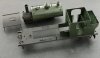
2195 CWM MAWR newly assembled motion. - YouTube

A short video of the motion.
The only thing to complete the build is the vacuum pump piston rod. Hopefully!
1f91e
 

davey4270

Western Thunderer
55. CWM MAWR, the Primer.

Some of the Crymlyn A Shop Boyos have been hard at work.


IMG_2597.jpg
Dai the Paint has evicted Orla Board, Crymlyn A Shop’s Irish tea lady, from his “studio” and after removing all traces or her Christmas Grotto can at last start preparing CWM MAWR for painting. Percy Veerance has been hard at work cleaning all the bodywork while Owen the Spanners has been adding a few missing rivets.


IMG_2599.jpg
The body was dismantled with some difficulty as I had forgotten to trim the shunter’s front step handrail where it extended beneath the footplate. This was trimmed to a few millimetres beneath the footplate and unfortunately now prevents the smoke box from sitting evenly anywhere where there isn’t a locating hole for it as on the footplate. Some care will be needed here with handling as it tends to roll over easily. The components were soaked for 24 hours in a bath of baking soda solution to neutralise any residual acidic flux then given a good scrub with an old toothbrush, “Shiny Sinks” and warm water.
I know people say about not using detergents but I then fill a washing up bowl with fresh warm water and add literally 1 drop of washing up liquid. The components are then immersed and given another good scrub before yet another scrub in fresh warm water. They were left in a warm place for an hour or so to dry but this can be accelerated with a hair dryer. Be careful with heat as any low melt solder can come adrift. Water can hide inside the boiler so be careful here. I have found that if the detergent is missed out the water leaves stains on the brass.
The missing rivets were added by applying dots of superglue with a needle in the appropriate places, ie around the rear bunker corners and one I missed at the front of the tank wrapper???
The picture shows the clean and ready for painting components on a black background from the top and clockwise: the cab/footplate assembly, the tank/boiler, cab roof, sand boxes, reverser reach rod and the firebox.


IMG_2600.jpg
The components were given a light coat of Upol 8 obtained from Halfords. This is an acid based primer that etches itself into the brass. Ordinary primer doesn’t stick to brass and will flake off at any opportunity especially on edges ruining your paintwork. The finish of the Upol appears to be identical to Halfords ordinary primer but perhaps an expert out there can tell us different? I remember using Precision acid etch primer and the instructions stated that the metal could be seen through the primer and this was ok so I didn’t overdo the Upol as it only needs a thin coat to cover the metal.
 

davey4270

Western Thunderer
56. Green Paint and Lifting Rings.

The model has had its green paint applied and while waiting a few days for it to harden I fitted the tank lifting rings.


IMG_2613.jpg

I had previously made 4 lifting rings for my models as they were required but a few kits back I made a dozen or so. That saves this job for a few more kits. I wind several turns of 0.7mm brass wire tightly around a 2.0mm drill bit and cut along the drill bit with a razor saw which separates them into rings as shown in the picture. I immediately place them in a small poly bag for safekeeping. Pick one out and tie a piece of white cotton to it which will retard it’s momentum when it makes a break for freedom and give you a sporting change to relocate it before the carpet monster eats it! Dress the cut edges with a file, place a small piece of paper around the anchor plate and hook it through the loop. Very carefully with 2 small pliers or strong tweezers close the loop.


IMG_2614.jpg

I had previously sprayed the model’s components that required green paint. Even though I just dusted the parts with the spray paint (Railmatch GWR loco green) it refused to take and ran into corners and rivet detail. Ignoring palpitations I quickly washed it off with white spirit and a soft brush. Luckily the primer had been on for 2 days and had hardened somewhat so the white spirit didn’t remove any of it although it did soften it a bit. Some streaky stains of the green paint were visible on the grey primer but I wasn’t worried about this as it disappeared under the next green coat of paint. The model was then given an even lighter dust coat and this time it didn’t run. Whether it was because I used even less paint or because the white spirit softened the primer, I don’t know! Anyway, each coat was given 30 minutes to set in a heated room before applying the next coat, about 6 light coats being necessary. I still had shadows where the paint didn’t totally cover around the rear lamp irons, base of the dome etc which I touched in with a very fine brush from a jar of the same Railmatch paint. This has proved to be invisible when dry. The picture shows the 4 lifting rings with their paper shields. “SUSIE WONG” lurks in the background.


IMG_2615.jpg

I’ll give the paint another week to harden as masking tape will be used to cover all the green areas so that the black can be applied. I placed a small blob of Blutac to hold the lifting rings so that the join was uppermost. The smallest spot of flux was wiped into the joint and a atomic sized particle of solder applied to it with a small, hot soldering iron. The solder should be sucked into the joint making the lifting ring a permanent, free to move fixture. Carefully wipe any trace of the flux off with a damp sponge, I use the piece of sponge on the soldering iron stand, and if necessary file off any excess solder. The piece of paper should protect the paintwork from any damage. Paint half of the lifting ring and leave for 48 hours before turning the ring to paint the other half. I did this while the paint on the main components is hardening to save some time later on. The picture shows a half painted ring on the front of the tank. The smoke box to its left will be painted black.
 

davey4270

Western Thunderer
57. The Black or Dai the Paint’s Overtime.

After waiting a week for the green paint to fully harden it was time to mask off the parts on the cab and tank components that were to remain green.

IMG_2638.jpg

Masking off is a time consuming affair cutting various shapes to cover protrudances like lamp irons, fire iron racks etc and an unfortunate side effect of “low tack” tape is that it doesn’t stick very well. Anyway, Percy Veerance won in the end and the components were handed over to Dai the Paint. The black has far superior coverage than the green and is a pleasure to use.


IMG_2638.jpg

Dai the Paint is happy with his overtime work and after waiting a few hours for the paint to dry the masking tape was carefully removed and the components will be left for a few days to harden.
 

Attachments

  • IMG_2639.jpg
    IMG_2639.jpg
    175.9 KB · Views: 5

davey4270

Western Thunderer
58. A Start on reassembly.

There’s a lot of painting to be done on small details. Wood for the cab floor, red for the buffer planks, cab controls, reverser reach lever etc, but today I just made a start on reassembling some of the body components.


IMG_2646.jpg

I used superglue gel to fix the green sandboxes to the footplate. I had previously soldered a piece of brass wire into a hole drilled underneath the sandboxes and another hole had been drilled through the footplate to position them. It was just a matter of holding a short rule against the front of the sandbox to set it parallel with the footplate and allowing the glue to set. I did this before fitting the tank/boiler assembly for ease of access.


IMG_2656.jpg

A bit of jiggery pokery was needed to fit the injector pipe work through the holes in the cab front, tuck the water feed pipes/valves into the holes underneath the tank, tuck the tab in the boiler bottom into the slot in the front of the firebox, tuck the handrail on the front shunter’s step into its hole in the footplate and locate the tab on the lower smoke box into its slot in the footplate. More by luck than judgement it all came together and the 4 small screws underneath the smoke box and inside the cab front were located and tightened.
 

davey4270

Western Thunderer
59. The Red Bits.

Dai the paint is only giving Cwm Mawr his attention every few days as time is needed for the paintwork to dry.


IMG_2689.jpg

Several days ago I made a start on some of the red bits. Red paint unfortunately has poor coverage qualities and here is a good example of where an undercoat needs to be used. Apparently pink or flesh make good undercoats but can affect the final shade. I only have a tin of flesh paint so this was used on the relevant bits, i.e., hand brake, reverser lever, regulator, reverser reach rod, buffer planks and vacuum stand pipes. I had previously painted the red on the hand brake lever, reverser, reverser reach rod and the regulator so I carefully threaded the reach rod behind the injectors and through the slot in the cab front securing it underneath the footplate with a dot of superglue.
The Guilplates cab side plates were probably as old as the kit and the half etched surrounds to the plates were cut straight and still intact so I stuck the plates on a piece of double sided tape and painted the surround green. The tape was carefully preened back to the width of the plate first by cutting the tape close to the plate then dragging a scalpel blade draw file fashion along the edge of the plate to remove excess tape. Using a suitably sized straight piece of Plasticard to centralise the plate they were carefully placed in position and and gently pressed for a few moments to stick them firmly. In about 15 years of using double sided tape, I’ve never had a plate fall off and they can be easily removed if necessary.


IMG_2690.jpg

I have a few pictures of the prototype working on the Weymouth tramway and the locomotive is absolutely spotless and polished to within an inch of its life! No doubt locomotives used for this purpose were kept in this condition to promote the GWR. A scruffy, knackered specimen would do little to impress future customers! Clearly seen in the pictures is a well polished copper chimney cap which unfortunately the kit doesn’t have so it was time to dig out my old tin of copper paint. The paint appears to be a clear lacquer with minute particles of copper. With apologies to Shania Twain “A single coat don’t impress me much”, but a few days later another coat looked tremendously better! There is so fine a “ridge” on the casting representing the copper that it was difficult to see when painting but I guess this is correct as the copper would be almost flush with the tube of the chimney. As an aside, when I built my ex CM&DPLRly pannier rebuild I had a problem obtaining the correct chimney and the one I used was cast brass, which I shortened, with a separate cast copper top to slip over it. Now that copper polished up would have looked superb but unfortunately the prototype didn’t have a copper cap so I had to paint over it. Typical!!!
Anyway, the buffer planks have had a single coat of red but I’ll check it in a few days to see if another coat is required. It was a bit of a chore trying to avoid the pipes around the buffer planks and the bunker behind the vacuum stand pipes but scraps of paper as masks helped. I’ll give the hoses a coat of matt black later. Although the pipes were sprayed matt black along with the footplate, there is the slightest sheen pickup by the camera.
 

davey4270

Western Thunderer
60. Piston Rods and Coal.

A few minor jobs today while the paint is hardening.


IMG_2691.jpg

A job I’d previously deferred was fitting a vacuum pump piston rod to the cross head bracket. The bracket had been attached to the cross head with thread lock as if it ever needed dismantling, a scalpel slid underneath would free it allowing the cross head to be withdrawn. After clearing the previously drilled 0.8mm hole of paint I cut a short piece of 0.7mm nickel silver wire long enough to touch the back of the vacuum pump and protrude a few millimetres past the cross head at its rearmost position. I carefully aligned it with a few tweaks to the cross head bracket and holding it parallel to the slide bars with a lump of Blutac. I pulled the rod forwards about 3mm to clear the end of the vacuum pump when the cross head is in this position. I decided to solder the rod to the bracket and smeared the smallest amount of flux on the rod where it touched the bracket and carrying a minute bit of solder on the iron, touched the rods and the joint was made. I snipped off the excess bit of rod and gave the cross heads a coat of a metallic steel paint. This is strange stuff which seems to firm a skin and will peel off unless fully dry. It’s a bit shiny at present but will soon be toned down other than the piston rods.


IMG_2693.jpg

The bunker coal was added by gently stuffing some scraps of black tissue paper into the bunker and roughly forming it into a shape looking like coal was falling in the middle but higher at the edges. I know that the lurching about of the locomotive tends to help level it so I also pulled the smallest bit of tissue through the bunker coal door. I soaked the tissue with diluted PVA and literally one drop of washing up liquid then poured some coal on top with more of the PVA solution on top of the coal. A small amount of coal was also spread by the bunker door on the cab floor to represent spillage and the whole kit left to dry.
 

davey4270

Western Thunderer
61. Couplings and Buffers.


IMG_2694.jpg

I chemically blackened the buffer heads with Carr’s steel blackening solution. The prototype buffer heads would have been dirty steel with a blob of black grease in the middle. It might be possible to replicate this but I feel that shiny steel should only be for crack express locomotives and black buffers look better on everything else but this is my personal preference. I’m not sure but I presume the buffers would stand 1’-9” proud of the buffer plank so I adjusted the retaining nuts to give this (12.25mm), but 12mm is near enough. I made a simple template to set them out of card, simply cutting out a 12mm square and placed the base on the buffer plank. Adjust the buffer retaining nuts to allow the heads to just touch the top of the cutout. I secured the nuts with a blob of black paint on the threads and as the nuts are visible underneath the narrow footplate I painted the nuts as well. I have shortened the tiny springs previously to reduce the compression strength but as these only just touched my template they were left in peace.
I had opened up the coupling hook slot earlier in the build to suit the Dapol screw couplings the shanks of which are quite wide. I’m not a fan of these as they readily fall apart and have a rigid tommy bar. I much preferred the earlier Lionheart version which were much finer with a hinged tommy bar. Unfortunately these are no longer available but if anyone reading this has some, I’ll be pleased to take them off you. Anyway, the hooks are good and as there is no room to fit a sprung version I modified them to suit. The shank was pushed fully into the buffer plank and I scribed a line on them hard against the inside of the buffer plank. Remove the coupling and drill a 0.5mm hole half a millimetre from the line away from the hook. Cut off excess shank and reinsert into the buffer plank. A dot of thread lock on a cocktail stick will run into the slot and a small length of 0.45mm brass wire acts as a retaining pin. Put some of the thread lock on the pin as well. Hopefully the picture shows this.


IMG_2698.jpg

After fitting the body I tried to fit the copper pipe running underneath the tank to the hole in the side of the smoke box. I then discovered that I’d forgotten to make an extra hole in the cab front to accommodate this. With some care and jiggery pokery I managed to drill an extra hole and thread some copper wire from the cab to the smoke box. I’m uncertain of it’s purpose as in early pictures of the prototype it appears to be some kind of lubricator but in later pictures it is much heavier suggesting maybe an ejector.

CWM MAWR First Run. - YouTube

A bonus here as 2195 makes its first run with the painted body attached. With apologies to Budgie.
 

davey4270

Western Thunderer
62. Bells and Buckets.


IMG_2704.jpg

Final details are being added, I had hoped to complete the build by the end of this month (January) which would have been 2 months building and another month to paint and detail the model. Unfortunately the new crew have not been passed out by the Crymlyn A Shop foreman and Dai Larfin, the store’s person, is still waiting for a delivery of lamps. The buffer plank numbers are in the stores but the Boyos don’t have any gloss varnish or Johnson’s Kleer to make an undercoat on the buffer plank so that the water slide transfers won’t show a silver surround. This will be matt varnished when dry.
The bell supplied with the kit was white metal and fractionally larger than the cast brass bell supplied with the new Agenoria kits now available from Andy Beaton of Ragstone Models. Andy kindly supplied me with a new brass bell which I polished and found it to be a perfect match for the bracket supplied with the kit. This sits on the L/H footplate just in front of the cab. The bell supplied was also found to be too big to fit in the bracket so thank you again Andy. It is suspended by a couple of black cotton loops secured by a blob of thread lock where they pass through a hole in the top of the support bracket. Unfortunately I have run out of superglue.
The CWM MAWR nameplates had their edges cleaned up with a fine needle file and polished. As the mounting surface is a shallow curve and not flat I was concerned that the double sided tape might not adhere sufficiently so I stuck the plates to a double thickness of tape and hopefully it will compress and swell sufficiently to do the job. Time will tell.


IMG_2703.jpg

I had forgotten to paint the toolbox and although it literally took seconds, it needed time between coats to dry. Anyway, I had drilled a small hole underneath and stuck a cocktail stick in it to ease handling and also stuck 2 this strips of black plasticard from front to back to raise it slightly off the footplate. I have seen this done on prototypes and it is probably to allow the underneath of the toolbox and the footplate to dry and prevent corrosion. The toolbox was once again attached with thread lock.
A piece of 0.45mm wire was formed into a fire iron by bending a loop at one end and an “L” shaped hook at the other end. Flatten this end in a pliers inline with the iron. Paint this rust colour and allow to dry. As for the length of the fire iron, imagine you are the fireman and would it be too long to rake the fire considering the proximity of the rear cab sheet? When the fire irons were stowed in the rack, the loop at one end had to be hooked over one of the brackets to prevent the iron from sliding along the rack and striking passing objects! So, hook the loop over the L/H bracket and also add a bucket. Galvanised buckets are available from the Minerva Engineering Company but be careful you’re not palmed off with plastic items! I understand that it was a requirement for steam locomotives to carry a bucket and hopefully Martin Wood will elaborate on this. On the prototype there was a length of chain to wrap around the irons to help secure them but I knotted some black cotton around them on the L/H and centre brackets. Perhaps silver cotton would look like a piece of chain.
There we have it, the model is as complete as I can make it until the crew are passed out, lamps arrive at the stores along with some gloss varnish. Work continues on a Barry Railway “F” class on a parallel blog.
 

Longbow

Western Thunderer

davey4270

Western Thunderer
Very nice indeed. As a old Weymouth man I'm encouraged to have a crack myself as Cwm Mayr was of course a regular at the Quay during its GWR days. On which topic, if you are looking to depict it at that location, you would want to add a fly shunting cable dangled along the footplate - viz:

GWR Great Western Railway Steam Locomotive Class Avonside Engine Co. 0-6-0ST. Ex- Burry Port & Gwendraeth Valley Railway No. 4. 2194 at Weymouth Quay in 1935 - 01/07/1935 - Neville Stead Collection

Yes, I modelled it as a Weymouth engine. I have 2 pictures at this location and am wondering how to depict the rope. It appears to have 3 folds back and fore across the footplate in front of the smoke box. It also seems to have a loop woven into it at either end. I have some fine string from a clothing tag that might offer some possibilities. I have a picture of 679 also on the tramway similarity attired.
I’m not sure if I’ve mentioned it in the blog but to any non Welsh speakers out there, CWM MAWR translates to BIG VALLEY.
 
Last edited:

Longbow

Western Thunderer
I believe it was a steel hawser, not a rope. Gerry Beale in his book on the Weymouth Harbour Tramway says that this was a characteristic feature of tramway engines until the early 1950s, along with shunters poles and at least one loose point lever on the front footplate.
 
Last edited:

davey4270

Western Thunderer
I believe it was a steel hawser, not a rope. Gerry Beale in his book on the Weymouth Harbour Tramway says that this was a characteristic feature of tramway engines until the early 1950s, along with shunters poles and at least one loose point lever on the front footplate.

Interesting comment, I have found some fine cord which I will use to represent a shunting rope/hawser. I would guess that as the tramway ran through streets any upright point levers could present a significant hazard to other road users and they were removed at these locations. The locomotive would carry a spare which could be used to change the point then removed again.

img433.jpg

This picture shows 679 on similar duties at Weymouth with a better view of the hawser. This is attached to a coupling link at the visible end and also note the copious amounts of horse dung. Dog poo on our pavements is nothing new. At least when it was white it was easier to avoid it!
The tank water filler lid retaining clamp is towards the front.

img740.jpg

A few weeks later at Weymouth shed it has been turned to the rear! Soon after this the locomotive was sold on 9/1929 to C. Williams of Morriston eventually ending up at Hook Anthracite Colliery, Pembrokeshire. Under NCB ownership it was transferred to Trimaran Colliery in 1951.
Apologies for going off subject but I researched this for my earlier model of 679.

IMG_3053.JPG

IMG_4155.jpg
 

Tim Watson

Western Thunderer
A very elegant little engine. Have you considered a little yellow varnish over the cross head to help it match the colour of the rods?

Tim
 

davey4270

Western Thunderer
Hi Tim,
The pictures of 679 were taken 2 years ago at the ALSRM at Reading, and unfortunately the cast brass crossheads don't match the nickel silver rods. I have tried a steel paint on the crossheads with a light wash of black, as with CWM MAWR, but it looks too dirty. I have painted the rods steel on another model but it looks too bright without weathering down. This is something I must think about, any suggestions are welcome.
 
Top