IanB3174
Member
Having loitered on forums and in model shops for many years and instigated many a layout in many a scale I still haven't constructed a full, operating layout.
I love making handbuilt track and always thought that would be the beginnings of something brilliant. But I forgot that is only one part of the model railway picture. I still have no clue about electrics or locos for that matter, weathering is a mystery, never having got that far. I can do basic scratchbuilding and kit building and that's about it.
So after a discussion with my brother, who's an inverterate planner, doer and finisher, I decided (he decided for me) that I should knock together a layout and get it to work rather than be a theoretical modeller. He has a point.
I have recently joined the S Scale Society and enjoy building in 1/64, but my output, barring trackwork, is painfully slow. I know I lack some skills which is why I'm building a practice layout.
It's a simple shunting layout, in OO, with commercial track for the most part (i'll be building one turnout) and using tried and tested techniques to prevent me wasting time on dead end experiments. It'll be DCC, because I have a Roco Z21.
The board I'm using was part of an older, larger project and is 1200x460mm Celotex edged with 6mm ply. Quite robust as it hasn't sagged or twisted in the 4 years since I made it. Trackbed follows my standard method of 5mm foamboard base with track glued down. I'm using Peco Bullhead turnouts and track.
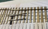
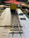
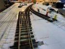
The two photos show the first two turnouts in place, joined with standard BH fishplates/joiners. This equates to 3 hours work so far.
They will be operated by linear servos and wire in tube. That's the plan. That's also an experiment, which I previously said I'd try to avoid. We'll see how the first one works before commiting to the others. They might just end up wire in tube with a manual lever. There's four turnouts plus one on the additional fiddle plank that I plan to add to the one end to form a runround.
There's no specific period or region at this point but it will likely be military/ex quarry/mine siding sort of thing. There's a lot of superb modelling on here that is both inspiring and seemingly unachievable. Time to learn more.
You can all watch in disbelief as I muddle myself into holes without a shovel.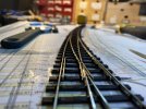
I love making handbuilt track and always thought that would be the beginnings of something brilliant. But I forgot that is only one part of the model railway picture. I still have no clue about electrics or locos for that matter, weathering is a mystery, never having got that far. I can do basic scratchbuilding and kit building and that's about it.
So after a discussion with my brother, who's an inverterate planner, doer and finisher, I decided (he decided for me) that I should knock together a layout and get it to work rather than be a theoretical modeller. He has a point.
I have recently joined the S Scale Society and enjoy building in 1/64, but my output, barring trackwork, is painfully slow. I know I lack some skills which is why I'm building a practice layout.
It's a simple shunting layout, in OO, with commercial track for the most part (i'll be building one turnout) and using tried and tested techniques to prevent me wasting time on dead end experiments. It'll be DCC, because I have a Roco Z21.
The board I'm using was part of an older, larger project and is 1200x460mm Celotex edged with 6mm ply. Quite robust as it hasn't sagged or twisted in the 4 years since I made it. Trackbed follows my standard method of 5mm foamboard base with track glued down. I'm using Peco Bullhead turnouts and track.
The two photos show the first two turnouts in place, joined with standard BH fishplates/joiners. This equates to 3 hours work so far.
They will be operated by linear servos and wire in tube. That's the plan. That's also an experiment, which I previously said I'd try to avoid. We'll see how the first one works before commiting to the others. They might just end up wire in tube with a manual lever. There's four turnouts plus one on the additional fiddle plank that I plan to add to the one end to form a runround.
There's no specific period or region at this point but it will likely be military/ex quarry/mine siding sort of thing. There's a lot of superb modelling on here that is both inspiring and seemingly unachievable. Time to learn more.
You can all watch in disbelief as I muddle myself into holes without a shovel.
Last edited: