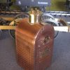
Enigma (Liverpool Lion)

geoff_nicholls

Western Thunderer
Jon, I've only just seen the photo of the coil spring and trailing axlebox from August. Is that how it still is? Could you follow Mike Williams' method of wagon springing, having the hole in the top of the axlebox sufficiently wide and deep to accommodate the spring when fully compressed?
 

Jon Nazareth

Western Thunderer
Geoff
I haven't done any more to the tailing axle but, I think that I will open up the top of the axle box and fit a spring inside which will be compressed by a sort of piston, a pin with a collar attached, that way only the pin will be visible.

Jon
 

Jon Nazareth

Western Thunderer
John
Yes, the fact that I'd made it a little too wide was a bit annoying. I managed to save the door and have fitted it to a new backhead. I've also made a new throat plate together with the boiler mounting ring. The wrapper is complete too. I need to make the square end nuts, that are actually the ends of the longitudinal stays, before I solder on the wrapper, and I can't see that happening this side of Christmas. The front and rear plates for the smokebox have been formed but, I need to make the opening and the doors before that can be soldered together.
So, there has been some progress but nothing solid just a box of parts waiting for further work.

Jon
 

Jon Nazareth

Western Thunderer
A step back in time when I first made this fire box, and made it too wide so, here is it's replacement complete with yokes that will support the Salter safety valves. The soldering came out better than the first as I decided to apply it to the inside of the fire box and to coax it along with the flame of my mini torch. The firehole door, I managed to salvage from the old one. The piece of angle below the door is as per prototype and is to support the floor. It will also help me to level the boiler et al with the frame as the top is level with the top of the frames and I shall bolt to it a separate piece of material long enough to span the left and right frame members. There are six boiler supports that are fixed to the firebox, boiler and smokebox and then to the frames. I'm not looking forward to attempting to make these but, they may go better than I'm imaging that they will at the moment.

Jon

IMG_3831.JPG IMG_3832.JPG
 

Jon Nazareth

Western Thunderer
IMG_3835.JPG IMG_3836.JPG

The first picture shows the ends of the longitudinal stays before I cleaned them up, which for me, were a b*&&%* to make. I needed six and ended up making fourteen. The first batch, made yesterday evening, were too short, I forgot to allow for the backing washer. The others I made this morning and came out a lot better.
The second picture shows them glued in with araldite. I got a bit ahead of myself as I wanted to rivet them on from the back but, with the wrapper in place, I couldn't fix them that way hence the glue.

Jon
 

Jon Nazareth

Western Thunderer
IMG_3838.JPG IMG_3839.JPG

I'm working on the steam turret at the moment and need to make the cotton reel looking fittings that take the arms from the safety valves. I can't think of a way to make the top flange with the piece that takes the rear of the arm, other than carrying out some very careful filing which I think is beyond me. Instead, I'm going to make the piece as a 'cotton reel', make a taller/longer clevice and fit it to the bottom flange. If anyone can think of an easy way to make/shape the top flange, I'd be pleased to hear it.

Jon


IMG_3838.JPG IMG_3839.JPG
 

Ian_T

Western Thunderer
If it's the part that I think Jon - then you could turn two 'filing buttons' (small cylinders centre drilled) to the required diameter - then bolt/clamp the part between them and use the buttons as a filing guide. The buttons don't need to be hardened - in fact I think it's unkind to your files to do so.

There are other methods of 'rounding' ends such as these (by milling) - either with a small rotary table or simply on a spigot but if you try this I'd suggest you attach the part to a larger (lever) part to keep your fingers clear. But filing buttons work very well and are simple to make.

Once filed to shape, the central slot can be machined with a slitting saw either in the lathe or mill.

Regards,

IanT
 

Jon Nazareth

Western Thunderer
Ian
Thanks for the reply but, I think you are talking about the forked end clevis pins whereas, I mean the two units that I describe as 'cotton reels' that sit on top of the steam turret. The top part in question is the flange that, in plan view, is like a tear drop. I'll try and find a picture.

Jon
 
Last edited:

Ian_T

Western Thunderer
OK, so assuming you are going to make the 'teardrop' as a separate part, then the simplest way is still probably filing buttons but to use a small jig-plate to get the straight sides right. As usual, it's probably easier to do than to explain. Mark out your part(s) and drill the 'bolting' holes the required distance apart. Make two sizes of buttons to match the required radii - with centre holes to match those in the part. Make a jig plate from scrap with two holes the same distance apart as those on the part. File the larger radius to approximate size before fitting the part to the plate. The larger hole in the parts could then be drilled to size. Thinking about it - it might be worth drilling the part blanks to final size from the start and turning one-piece combined button/pins to hold the parts on the jig plate. Anyway, hopefully you get the general idea.

You can also do this work with a rotary table & mill set-up - rotating the table to give the larger radius and a straight mill run for the sides. But if it's just two small parts - I think filing is probably easier & quicker...

PS Hope I've got the right bit this time!

Regards,

IanT
 

Jon Nazareth

Western Thunderer
IMG_3845.JPG IMG_3846.JPG IMG_3847.JPG

This is the body of the steam turret. I meant to take more pictures but, it slipped my mind. The body is a brass turning which has a square piece of nickel, silver soldered onto it as the skirt. The whole was held in soft jaws and the skirt was turned to diameter. I then marked out for the rivets which were to be pressed out. The problem was that I couldn't get the turret close enough to the anvil and therefore decided to drill out for actual rivets. Tomorrow, I'll make an aluminium anvil which will support and protect the heads. I will be using brass rivets and the ali being softer, the heads of the rivets should retain their form.
The curve of the turret was formed on a piece of abrasive paper double sided taped onto drum, held in the lathe. The turret was held against the drum and the seat formed in next to no time. I'll post a picture of the sanding drum tomorrow.

Jon
 

Jon Nazareth

Western Thunderer
IMG_3849.JPG IMG_3850 - Copy.JPG IMG_3851.JPG

The first picture shows the 'drum' mentioned in the previous post. The next two, the turret so far. It is a good fit on the firebox and I think that the 'gap' that can be seen between skirt and wrapper is just a shadow. I was going to soft solder the turret to the firebox,which is why I silver soldered the skirt to the body, but in the end, I drilled 8BA clearance holes in the skirt and the top of the wrapper. I then glued in with araldite a brass cheese head screw into the top of the firebox. The next item on the list are the two arms that pass from the top of the turret and connect to the Salter safety valves. I'm not looking forward to this as they don't look that easy to make/fabricate but, faint heart and all that sort of thing.

Jon
 

Mike W

Western Thunderer
I'm not looking forward to this as they don't look that easy to make/fabricate but, faint heart and all that sort of thing.

Sounds like you Jon, tackle a tricky job with little confidence and that most wouldn't attempt ... and end up with something quite exquisite! That whole firebox is just superb.

Mike
 

Spitfire2865

Western Thunderer
Save some talent for the rest of the loco!
For the safety valve arms, It seems a fairly plain arm on most examples of the era. What do you feel is challenging about them?
In the US at least, the arms all seemed to be nothing more than a tapered flat bar with a few holes drilled through. On my American, I ended up using a couple of Mikes wagon brake levers cut down and drilled as they already had the correct taper and near enough correct thickness.
 

Jon Nazareth

Western Thunderer
IMG_3854.JPG IMG_3855.JPG

Trevor
Here is the drawing of the safety valve arm. If it had been a straight/tapered arm then, probably quite doable. However, it has that slot which carries the plunger and that scales at, 0.069" x 0.024" so, not an easy thing to fabricate. Well, for me at least as I find that these small pieces are difficult to hold.

Jon
 
Top