FSIJ - 16mm narrow gauge

Greengiant

Western Thunderer
Track laying has started, first is board six.
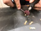
The plates were cleaned up with a mop in a wizzy disk.
43524882141_5d3bd4e75f_k.jpg

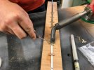
Clip positions were marked out, then they were soldered to the rail using a 150 watt iron to get enough heat in quickly. We made a simple jig by routing a groove in some plywood at the depth to hold the upturned rail and the clips in exactly the right plane.
43524889331_cc58b3c94e_k.jpg

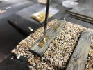
For rail end clips and some mid point clips we have some that have been drilled to accept small screws.
43524876811_9c7c5ce5e1_k.jpg

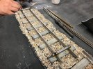
With end clips in place we used a rail bender to curve the rail until we got the flow we wanted.
42807679074_e2ba847356_k.jpg

Note that the plates are not always central on the sleeper width, this is not an error, that is how they appear on the actual railway.
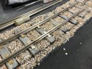
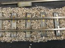
43524886531_405bece9f0_k.jpg

43524888141_2ed6fd2bed_k.jpg

One board getting there, still to do is fitting of the pandrol clips, blackening of the rail and final fixing to the sleepers.
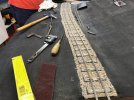
43524890731_1edd389e86_k.jpg

We got as far as board four with the track laying initial stage.
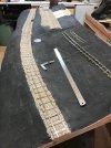
44027173122_3efcd7e36f_c.jpg

On the previous two boards the fishplates were soldered on using an RSU.
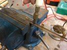
44027170962_76d1dbdea4_c.jpg

This photo shows that we cut the web and head of the rail to simulate rails joins.
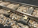
44027171972_a9f2845047_c.jpg

Martin
 

Greengiant

Western Thunderer
Back to the traverser, not a vast amount has been done other than the parts for the traverser have been made and trial fitted to the baseboard.
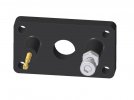
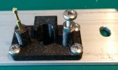
The units that hold the adjustable end stops and power supply plunger pins have now bee 3D printed.
27840221787_b6f190ecf3_c.jpg

Here seen mounted on one of the end plates but yet to have the power supply pins fitted.

44428408280_f0233caa8c_c.jpg

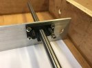
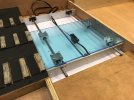
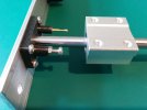
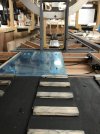
And here seen with the traverser perspex (with protective film still applied) and a linear bearing. The function of the adjustable end stop can be seen in this photo.

44428408320_ffcf087c6b_c.jpg

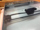
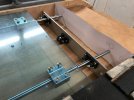
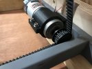
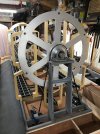
This photo shows how the drive belt will be attached to the traverser table, not at all clear in this picture is how the belt interacts with the mounting block, I will try and get a better picture to show how this works.

31306413117_403ae0e36b_c.jpg

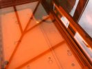
An overall view of where this will be sited, our intention is to have this fully on view and showing all the workings.

31306413607_faf1eddff1_c.jpg

I now have some close up photos of the parts we have 3D printed or CNC'd for the traverser.

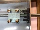
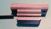
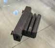
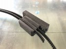
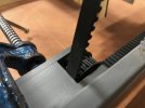
This part is the unit that transfers the drive movement from the belt to the table. The belt which we will cut to length just slides into the unit from the side, the teeth printed in the slot locate with the teeth in the belt, this gives us the ability to adjust belt length by one tooth which means final tightening will be minimal, plus we can buy any over length belt, no need to buy one the exact length.

44497507170_79c531b0f0_c.jpg

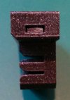
This is an end view, the lower slots are for the belt, what will not be obvious is the slot on the upper part. This slot is wide enough for a nut over the flats, which means we push in a nut which is now captive and will not rotate to receive a bolt from above through the traverser table to allow the fixing in place of this unit.

45590677824_87338a1f6c_c.jpg

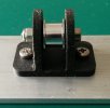
This is a 3D printed mount for the end belt pulley attached to the end of the traverser well upright.

44497506850_4e7911155b_c.jpg

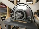
Here is the end wall of the well showing the belt pulley wheel and two 3D printed end stops which also house the plunger pick ups, only one plunger has been fitted at the moment.

45590677914_5c4aede235_c.jpg

One of the linear bearings mounted on a rail showing how the end stop and pick-ups will interact.

44497506960_2978065475_c.jpg

A close up of one of the stop units showing clearly a Pogo pin, you will see the head on the Pogo pin is made up of a series of points, the benefit of this type of pin is it is effectively self cleaning, it rotates in the housing giving a slight movement which should ensure any dirt on the contact surface is cleared.

44497507130_82bdefb27b_c.jpg

A very short video showing this end stop in action.


Martin
 

Greengiant

Western Thunderer
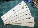
A small update, final fitment of the traverser is nearing completion, the well end panels were drawn up, printed out to test for accuracy, then cut from 3mm ply as three laminations on the laser. I had to do it this way because at the time I only had a 5 watt diode laser.

45995600305_c0e3ee30f0_c.jpg

45995599865_e6ce849f4c_c.jpg

39945334293_2f26944e75_c.jpg

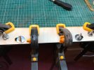
These were then glued up to give 9mm which will be deep enough to hold the M6 'T' nuts.

31969160617_4f4670935e_c.jpg

The workshop has now been rearranged so the four straight scenic boards can be left up permanently which will help with the track laying.

I have upgraded all of the fluorescent lights in the workshop to 6000K LED tubes, these have made a big difference to the lighting. Some were very straightforward to upgrade, they came with a special LED fuse starter, so just a straight swop. Some others were a little more involved, but basically meant removing the ballast and associated wiring, but nothing difficult. Added benefit of instant on and uses a lot less electricity.

Martin
 

Greengiant

Western Thunderer
We are now in February 2019 and getting nearer to assembling the RotaYard and traverser for testing the installation on the two baseboards.

Here are some close up shots of the 3D printed belt fixing/adjuster for the traverser drive belt.

39993253833_71906852da_c.jpg

33082340008_7b5506f703_c.jpg

We have the host of the podcast Model Rail Radio paying us a visit this week, so the workshop has had a bit if a tidy up, although it does not look like it has!

Some sections of The Yard and First Sunday in June have been erected so he can see first hand what we have been up to.

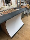
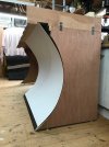
While doing this we took the opportunity to trial fit up one of the curved lower fascia panels and have a discussion as to how best to achieve the mounting of said panels. The dark coloured bar at the foot of the curved fascia will eventually be painted white, there will also be full height, shaped panels for each end of the layout.

A few shots of a lower fascia panel on one of the fiddle yard boards.

46233175114_fc9e654ed4_c.jpg

This view shows how the panel is flexed and then released to fit in the holding grooves.

46905739672_6d00f0df85_c.jpg

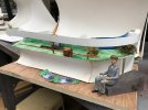
While getting things ready for the visit we dug out the original concept models which have taken a bit of a battering over time.

The first concept model.

46233504964_0b5cff19a0_c.jpg

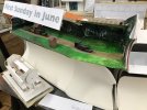
The second concept model and early RotaYard.

39993254643_e34ea7b9d9_c.jpg

Martin
 

Greengiant

Western Thunderer
We achieved a bit of a milestone this week, the first powered run of the RotaYard.

We temporarily wired up the drive motor...

46964860602_6d6a1bc358_k.jpg

...and clamped the belt tensioner in place...

40052184973_2710102d53_k.jpg

...a rough bit of packing for the end bearings.

46292661664_b822ee98e3_k.jpg

Traverser plate in position.

40052185163_859bc74db7_k.jpg

All ready and fingers crossed while we power up the motor.

46964861212_1475d06239_k.jpg

A short video of the very first powered run.


Martin
 

Greengiant

Western Thunderer
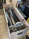
We have made a storage box for the RotaYard, this was a multi-part requirement:
1) Store it so it takes up less room than it's component parts spread all over the workshop
2) Protect and keep it clean
3) It can be easily moved for when it will shortly be off for the final fitment of the drive system and associated detectors and electronics.

48081254272_46bc6bf682_c.jpg

The combined box and RotaYard is a heavy old lump to carry, we shall probably make some form of trolley when the time comes to exhibit.

Martin
 

Greengiant

Western Thunderer
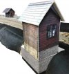
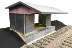
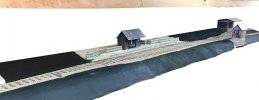
I have not been able to update the tread of late being busy with work, along with a couple of us get involved with our classic cars and meetings until late winter and the layout takes a bit of a back seat, so to generate some enthusiasm to get on with things, we made some rough colour mock-ups of the three buildings on the layout and positioned them in place to get a feel for composition.
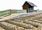
This is the run round end of Stony Shaw station.

48081157276_ea82fb0bb5_c.jpg

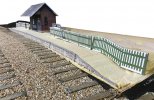
The approach end of the station.

48081255362_d927f89977_c.jpg

Signal box with the station in the background, a very difficult view point on the real thing unless you had a very tall step ladder!

48081252957_0c960a8bb2_c.jpg

Finally the goods shed.

48081157281_aa48f448a3_c.jpg

A view of the first four scenic boards. The plywood at the top was for helping us decide fascia height, we have now set this at 21 inches from underside of fascia to the bottom of the baseboard, which is a lot lower than this picture shows.

48081152266_63330013d2_c.jpg

Martin
 
Top