GCR Class 5A - LNER/BR J63

Rob Pulham

Western Thunderer
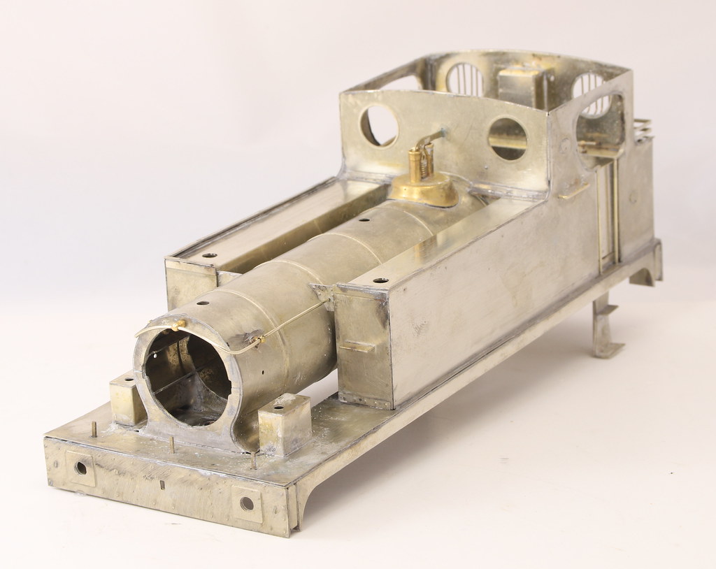
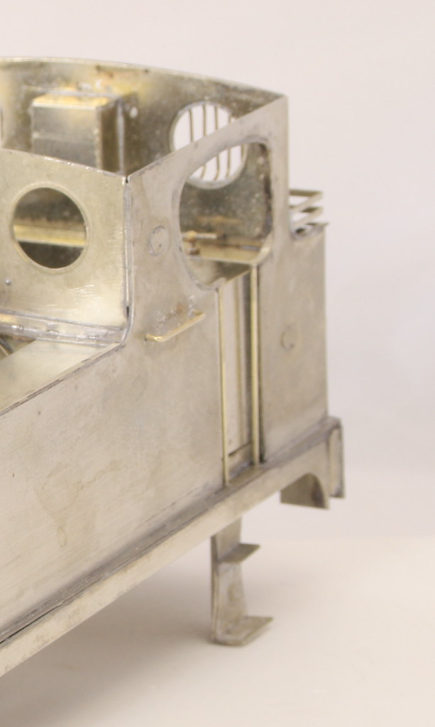
I am pleased to say that the replacement side has been a complete success and even in bare metal, if you didn’t know I doubt that you could tell that it wasn’t original.

Each side has a couple of ovals representing works plates so I used some off cuts to file up a couple of replacements and soldered them in place before fitting the side. I took measurements of the side that I had taken off to get the correct placement.

50717648503_4b7b261c9f_b.jpg


50717649723_6a35d0e3b0_b.jpg


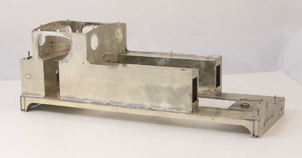
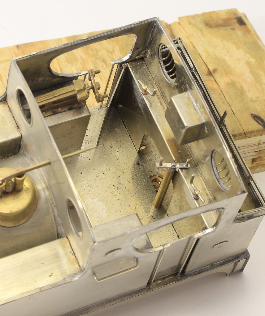
Before finally soldering the new side on I fitted the front and rear of the cab and the cupboard on the cab and their overlays.
Once they were all in place, I added the beading around the cab opening. Although I am sure that I used them last time I failed miserably to get the beading to slot onto the tabs in the cab openings. In the end, I filed them off and did it as I would have if there had been no tabs. Using the opening as a former I pre-bent the beading to shape and them with the aid of self-locking tweezers soldered them in place. I will have to revisit one of them as while taking photos this morning I noted a couple of small gaps that need filling.

50718467692_e8dbe84681_b.jpg


50718386491_3e81a65472_b.jpg


50717650098_4d611bbbff_b.jpg
 

Dave Holt

Western Thunderer
Rob.
As you say, the replacement side looks indistinguishable from the etched version. Well recovered. I had a similar problem with a tender side overlay and had to resort to buying a complete replacement tender body kit just to obtain a new side - turned out the kit supplier could have supplied a replacement side, if only I'd asked!
The loco is coming along nicely.
 

Rob Pulham

Western Thunderer
Rob.
As you say, the replacement side looks indistinguishable from the etched version. Well recovered. I had a similar problem with a tender side overlay and had to resort to buying a complete replacement tender body kit just to obtain a new side - turned out the kit supplier could have supplied a replacement side, if only I'd asked!
The loco is coming along nicely.

Thanks Dave,

Ouch that's a bit gutting but sometimes it never occurs to ask. These kit's are not available at the minute so I had no option but to go for it.
 

Rob Pulham

Western Thunderer
Progress has been slow this weekend, but a mystery has been unravelled.
You may recall that when I started the footplate, I couldn’t find two out of four part 60’s? Well today I found them…

I started yesterday’s session by rolling the boiler and it mentions using part 52 to ensure that it’s round.
This is the drawing of part 52

50741594546_1b3fb27db3_w.jpg


I found it amongst the remaining bits of etch and tried it in the boiler all was well.
Then I started to assemble the inner support frame for the boiler using the diagram below and photos of my previous build.

50741730277_975afbec66_b.jpg


9056961598_6d51be589d_b.jpg


In my previous build I hadn’t used part 52… so I started questioning why not.
Although I obviously hadn’t worked it out before due to lack of experience it quickly became apparent that there was something wrong with part 52.

50740858003_66a0a35cfb_n.jpg


The photo above shows both sides of part 52 as etched. Although it’s one piece when you check against the drawing snip above it should in fact be three parts, 52 and 2 x part 60 (the missing parts). It looks like when he drew the artwork Garth Patrick got these bits on the wrong layers and the bit’s that should have been etched though have been half etched on one side and the outer ring which should have been full thickness has been half etched on the back making the part completely useless. I contemplated cutting the ring out with the piercing saw but I obviously managed without it on my build so could on this. As it happens in my spare etch box I found a semi circle the correct diameter which I will attach with a couple of bits of scrap to support the firebox end of the boiler tube.

Photos to follow once I have done it.
 
Last edited:

Rob Pulham

Western Thunderer
This morning I added the semicircle of spare etch attached with a couple of small bridging pieces made from scrap etch.

50742913583_00bfec7165_b.jpg


50743758522_cfb0908e60_b.jpg


I had already rolled the boiler but hadn’t soldered the seam so that was done next and then I realised that the two slits which allow for the curve out of the smokebox base the fit the smokebox saddle hadn’t quite etched right through. A simple task to cut down it with the piercing saw once the seam was soldered. But equally had I noticed it before rolling the boiler I could have done it in the flat with a blade.

50743757987_7252208e3e_b.jpg


There are some tabs on the ends of the inner frame at the firebox end but I can’t see any corresponding slots in the cab front, so I think I will have to cut those off to get it to sit in place correctly. But that will be a task for next year when I resume.

50742914148_7f10e0f33c_b.jpg


50742913873_f5d8b9ab68_b.jpg
 

Rob Pulham

Western Thunderer
I am not sure where last weekend went as I had hoped to achieve a bit more on this build but sometimes that’s the way it goes.


First off I cut out the Diane Carney number plates with a no 6 blade in my piercing saw and filed them to final size. Not knowing for certain whether the actual plates had a rim around the beading or whether the beading was in fact the edge of the plate I left two of them with a rim and asked Brian which he preferred.


Then I soldered the boiler to the formers and fitted it to the body. The bottom edge of the boiler section that fits between the tanks has three tabs either side which fit into corresponding slots on a fold out on the inner tank sides. What a fiddle it was to get all six in the slots together. I hadn’t slept well on Saturday night and in the end, I had a snooze before my brain was clear enough to get them all in place.


Rob Pulham

Western Thunderer
Modelling time has been a little sparse just lately, we were fortunate to be gifted a fair quantity of topsoil from a neighbour’s garden which is to be used to level off or reduce the slope on our front lawn and initially I was wheelbarrowing it in.
I would never have moved it all manually in a timely manner, so the gent doing the groundworks offered to use his digger and dumper to bring it round to our house. Now it all needs to moved away from the dwarf wall so that the wall can be built up higher and then finally levelled off.

50878227216_985c828af5_b.jpg


I have managed to do bits in between and I have got the plunger pickups ready for installation and also prepared all the brake parts ready for fitting. I felt that the brake spreaders were a bit on the flimsy side so I used some of the scrap etch to double the thickness before fitting the clevis’s.

50878194486_ae416c2790_b.jpg


Although I never thought to take a photo of them, the layers that make up the brake shoes and hangers come tagged together in small outer frames which can be placed over each other and gripped as one, to allow the parts to be soldered together before cutting out the individual brake hangers complete with shoe as in the photo above.
 

Rob Pulham

Western Thunderer
With mojo fully restored in between going for my Covid jab I cracked on and got the brakes assembled and soldered in place. I left the crankshaft from the brake cylinder loose for the moment just in case I do find a way to fit the brake cylinder.

I made up a couple of adjusters from some telescopic tube, filing the larger pieces into hexagons to represent nuts at each end.

50975722991_ce03757976_b.jpg


Next up is fit the sand pipes then to work out how best the motor will fit with the body on. The latter should tell me whether I will be able to fit the brake cylinder after all.
 
Last edited:

Rob Pulham

Western Thunderer
I managed to get the sand pipes fitted and then moved on to fitting the motor to the chassis and testing within the body.

On this there is good news in that I should be able to squeeze in the brake cylinder albeit that to avoid the plunger pickup I will have to fit it to the rear of the frame spacer instead of the front but at least it will be there.

Then there is bad news. Brian has provided a really nice ABC motor/gearbox unit. Sadly, the kit is designed for a can motor with simple gears mounted to a frame spacer. The motor gear box will fit into the boiler area no problem but where it does cause an issue is that it interferes with the rear brake cross beam which I think I am going to have to cut

50993520646_4a003bd8da_b.jpg
 

Rob Pulham

Western Thunderer
Things have been quietly progressing with the Class 5A and the number of etched parts is diminishing.

The other thing I have been considering is the motor position and I have been trialling fitting it to the middle axle which would remove the need to chop some out of the brake cross beam.

By nibbling some of the boiler/firebox former away it has allowed the motor to slip inside and run without any apparent issues. What I am not sure of yet, because I still have to test it, is whether it affects the movement of the compensation beams.


There isn’t a great deal of room for movement in there so I need to test it before making a final decision.
 

Rob Pulham

Western Thunderer
This is a bit of an addendum to the last post with photos showing where I am at.


A weak area of the kit which to be fair is admitted to in the instructions is the cab roof. It’s half etched and as a result besides being very thin it also has a tendency to curl in the wrong direction for the curve of the cab. I wanted the roof to be removable so I did exactly the same on this one as I did on mine.

After fitting the curved ribs that are supplied, I cut a smaller piece of 10 thou nickel to fit inside between the ribs to add strength and I also added a couple of rain strips from 1mmx1mm brass angle which conveniently hides the holes left by etched slots.


.

There are not many more bits of etch to add before I get to adding the castings and final details.
 

Rob Pulham

Western Thunderer
Today I rechecked the motor and gearbox on the centre axle with all the other axles in place. Sadly, it was as I feared, the tight fit of the motor in the boiler area pushed the compensation beam down and left the chassis rocking on the centre axle. So back to plan A fitting it on the rear axle and cutting into/the brake cross beam.

Before doing anything drastic I took time out to knock up some ashpan sides and they have cured the gearbox visibility issue.


51030101462_309a3585c0_b.jpg


51030100547_33471db17c_b.jpg


That still left the gear touching the brake cross beam so I bit the bullet and cut a section out of it.

51030226922_26141c1072_b.jpg


Rob Pulham

Western Thunderer
Over on RMweb Mike Edge (of Judith Edge Kits) kindly pointed out that I had the ashpan sides correct but fitted the wrong way around – slope to the rear instead of the front.

I am very grateful for this because it’s an easy fix (already done) and was a detail that I was struggling to find. The GA I have only show’s an outline for the ashpan and all the photos I have the detail is lost in the gloom.
I had forgotten to take photos of them before fitting so taking them off to swap them around gave me the opportunity to do so.

I measured the space where they were to fit and cut a strip of a sheet of 10thou nickel 30.5mm wide. From this strip I cut two pieces each 17mm long. This left a piece approx. 30mm long and I measured 5mm up from each opposite end and then cut the piece diagonally across.

I wasn't sure that I have described that clearly so I knocked up a sketch in paint.

51041189992_84a5cf8108_m.jpg


Once I had all the parts cut out, I placed each bottom edge in my hold and fold approx. 1.5 mm in and gave it as slight bend and then solder them together in handed pairs to give each ashpan side as below.

51041146887_7a6736d29e_b.jpg
 

Rob Pulham

Western Thunderer
I haven’t had much workbench time in the last couple of weeks or so but when I have I have been slowly working on the chassis of the Class 5A fitting the pickups and getting it to run. The latter being a bit of a trial.


In order to make it so that the motor and pick ups can be removed without having to unsolder anything I made a frame spacer from a spare out of another kit and screwed a piece of Vero board to it


This is where the fun began, despite it running lovely when the motor was connected directly as soon as I added pickups in to the equation the rods started jamming at every turn which in turn forces the compensation beams up and down to one extreme or the other. This caused more than a few mutterings. One thing that I noticed was that in retaining the Dereck Mundy Crankpins at the rear albeit in a modifified form on the centre axle the thick boss was still causing issues by pushing the coupling rods in to an open-ended wedge shape. I had dismantled one side with the plan to carefully extract the crank pins and turn the bossed down on my Unimat SL. Life intervened and I bought a Unimat 3 early last week, so having collected it from Driffield on Tuesday, I did them on that instead.


It now runs much better on the rolling road but I am sure that once I get some weight in it and on a test track it will be fine. The rollers on my rolling road are set a lit far apart and sometimes that introduces a bit of a waddle which doesn’t help when trying to resolve running problems. – Prompted by typing this, I found and added some small washers which have taken out some of the side play on the rollers and running has improved already.
 

michael080

Western Thunderer
Rob,
are you sure that the lower left wire in the first picture has any contact to the board below? Looks like it is just floating above. Is that leadless solder? Its colour appears strangely dull.
Michael
 

Rob Pulham

Western Thunderer
Rob,
are you sure that the lower left wire in the first picture has any contact to the board below? Looks like it is just floating above. Is that leadless solder? Its colour appears strangely dull.
Michael

Hi Michael,

It's just the photo, the wire is solidly attached. The solder is cored electrical solder rather than the more usual 145 or 180 that we would normally use in modelling - I didn't want to be washing flux of the electrics.
 

Rob Pulham

Western Thunderer
While awaiting more building materials I had some time in the workshop over the last couple of days and this has allowed the Class 5A to move much nearer to completion. All the etch parts are now on the body with just the balance weights to fit to complete all the etched parts.
From there I moved onto the castings, at the beginning Brian and I discussed the castings and since they were pretty poor (certainly when compared to the castings that came with my kit a few years earlier) and we replaced as much as we could but retained the Chimney, dome and Smokebox door. The dome and the smokebox door did clean up and don’t look too bad now but the Chimney when I examined it closely had some holes in the flare at the base. I filled them with lowmelt and reshaped the flare. This means that I will have to use epoxy to stick it on as I don’t want to risk any heat undoing the work on the flare.

51122718976_f7c5860331_b.jpg


51122462864_7628c7a5d0_b.jpg


The castings after clean up

51122718016_c003d36c06_b.jpg


Cab interior details

51122147832_b5b0874c77_b.jpg


51125076956_073f1c622e_b.jpg


51125885775_488aabefa3_b.jpg


51124986438_c2e281fe01_b.jpg


The Safety valves are from Laurie Griffin and they too had a prominent mould line across the top which required a bit of works to remove but still infinitely better than the reject whitemetal offering. I understand that this kit is now with Iain Young of Sans Pariel/CSP and that he intends to remaster all the castings. The kit will benefit greatly from that, I think.
 

Rob Pulham

Western Thunderer
Amongst the castings in the kit were what I originally thought were a couple of Ross Pop safety valves but it turns out that they were in fact the lids for the sand boxes either way they were not great.

What a great opportunity to make something meaningful with the new lathe, thinks I.

So, I turned up a pair of sandbox lids

51130042839_958af58072_c.jpg


51130078724_b62fb7f127_b.jpg


Finally, one with the obligatory 5p piece for scale

51130043004_307886e240_b.jpg


I have to confess that these were my second attempt. The first pair were okay but I hadn’t quite worked out how to make the two identical so there were some slight discrepancies in size – probably not really noticeable at this small size but I knew I could do better so I did.

After making the first two sandbox fillers I turned (if you will pardon the pun) my attentions to the oilers. While buying other castings I had bought some oilers for the side of the smoke box and a set for the footplate. Having examined the ones on the footplate more closely in the photos I realised that the castings would be correct so I turned up a pair of those too. They were very similar to make, aside from I drilled these 0.8mm to take a piece of nickel rod to mount them.

I could have left a turned stem on the oilers but I need to be able to bend it so I reasoned that rod would be better for bending as I thought a turned stem would be likely to break off.

51129965316_ebe610ff0a_b.jpg


And again, with the 5p piece

51130042704_5dcc8921e5_b.jpg

The collets and chuck were invaluable and this type of thing really satisfies my urge to make things…
 
Top