You are using an out of date browser. It may not display this or other websites correctly.
You should upgrade or use an alternative browser.
You should upgrade or use an alternative browser.
Ian_C's workbench - P4 and S7 allsorts
- Thread starter Ian_C
- Start date
Threadmarks
View all 176 threadmarks
Reader mode
Reader mode
Recent threadmarks
Bradwell WD 2-8-0 - eccentric rod pin Bradwell WD 2-8-0 - working valve gear and motion, springs, brake shoes Bradwell WD 2-8-0 - Brakes that really do bring you to a stop... Bradwell WD 2-8-0 - injectors (welcome back threadmarks) Bradwell WD 2-8-0 - sanding gear Bradwell WD 2-8-0 - big bits coming together at last The 'no update' update Another no-upate update - and season's greetingsIan_C
Western Thunderer
No, I wasn't. Thank you.Ian,
are you aware of the Weinert rivets for walschaert gear? I used them for all my 4mm models.They are fixed with a small punch from the backside with a pointed mandrel. No soldering required.They have also very nice bolts for the coupling rods.
View attachment 149720
Michael
Bradwell WD 2-8-0 - the return cranks
Ian_C
Western Thunderer
I know I'm not the first person to have wondered how to make removable return cranks that end up in the correct angular position every time they're installed, but there's little written about it in the reference works on my bookshelf. The late , great Guy Williams hardly mentions it in either of his Wild Swan books and Geoff Holt advises to solder the crank to the end of the crankpin, which is no help if your crankpin is secured from the inside of the wheel, as they often are in 4mm. So, another design challenge, and back to the CAD screen.
The cyan item is the steel crankpin, as described in more detail in a previous post. It's 1.6mm in diameter and threaded M1 x 0.25 down the centre. In this case it's only half the crankpin. The other half is the green top hat bush that carries the return crank, also threaded M1 x 0.25 through the centre. There are thin washers, in orange , to space the coupling rod off the wheel and the connecting rod off the coupling rod. The return crank is the etched component from the kit, and the little pink boss is to thicken up the crank at the end where is will be threaded M1 x 0.25 for the eccentric rod pin. This way the eccentric rod can be disconnected from the crank to allow the complete cylinder and valve gear assembly to be removed, and the crank can be unscrewed from the wheel to allow the connecting rod and coupling rod to be removed. The eccentric end of the crank arm on the WD has a 14" crank throw and is timed at about 95 degrees behind the crankpin. Interestingly it doesn't quite work out that way on CAD, and I think it is because the etched crank arm centres are a little short. But not to worry. There's no practical way of timing the thread on the top hat bush to land the crank arm in the right position, so the arm is soldered to the bush once it's tightened to the crankpin thread.

Make some parts. The wheels here are the original Gibson wheels that have been sanitised and trued with a brass axle bush (previous post etc...). The crankpin holes were drilled out at exactly scale 14" throw this time, rather than drill out the existing hole to 1.6mm. Interestingly (or not) the moulded crankpin holes in the Gibson wheels were not quite a 14" throw, which probably accounts for some of the quartering challenges previously where I had a mix of some wheels with the original Gibson crankpin position and some with an accurate scale 14" throw. Parts are straightforward lathe work, albeit quite small.

Here's a wheel with the half crankpin installed, and with a length of M1 x 0.25 thread fixed with Loctite 601 high strength retainer. That part needs to stay put when the crank arm is screwed and unscrewed.

Same wheel from the inside. Note the crankpin bush doesn't contact the axle bush. Life's simpler if there's no electrical contact here with this pick up system.

Crank arms with the tiny boss silver soldered in place, so that they don't become unsoldered when the arm is soldered to the crankpin boss. Both the inside of the arm and the outside of the top hat boss are tinned with 145 degree solder. One of the top hat bosses is tightened to the crankpin thread ready for soldering. In passing, I've started using a small rectangle of medium density EVA foam to do assembly work on in place of the usual cutting mat. I find that small parts don't roll away on the foam, and if dropped on the mat they just stay where they land.

The thread stops a little short of the top of the thread to reduce the chances of solder getting to it. A smear of grease on the thread also helps.

The arms are positioned by eye and held in place with the tip of a scalpel blade, then sweated to the crankpin bush with a quick, hot iron. Now the arms will screw on tight in the right position every time. They will be specific to the left and right sides, so a small L and R is scribed on the inside of the respective arms.

All that's left to do is put the axleboxes on the axle and quarter the wheels. I'm hoping that this won't mean another chapter of quartering and coupling rod wars if these wheels don't closely match the previous set up.
It's worth noting that on the prototype the crankpin on the driving axle was 6-1/2" to 6" in diameter, or 2mm to scale. So the 1.6mm crankpins here are slightly undernourished. Things would have been a little easier and slightly more robust with 2mm crankpins. Next time. You can also see that the moulded crankpin boss is not really large enough for a 2mm crankpin, so although the Gibson wheels look quite nice they're not 'that' accurate. Now I examine some WD photos it looks as if all of the wheel centres were cast to the same pattern, and the crankpin boss appears significantly bigger than on the Gibson mouldings. But if I hadn't mentioned it who'd have noticed?
The cyan item is the steel crankpin, as described in more detail in a previous post. It's 1.6mm in diameter and threaded M1 x 0.25 down the centre. In this case it's only half the crankpin. The other half is the green top hat bush that carries the return crank, also threaded M1 x 0.25 through the centre. There are thin washers, in orange , to space the coupling rod off the wheel and the connecting rod off the coupling rod. The return crank is the etched component from the kit, and the little pink boss is to thicken up the crank at the end where is will be threaded M1 x 0.25 for the eccentric rod pin. This way the eccentric rod can be disconnected from the crank to allow the complete cylinder and valve gear assembly to be removed, and the crank can be unscrewed from the wheel to allow the connecting rod and coupling rod to be removed. The eccentric end of the crank arm on the WD has a 14" crank throw and is timed at about 95 degrees behind the crankpin. Interestingly it doesn't quite work out that way on CAD, and I think it is because the etched crank arm centres are a little short. But not to worry. There's no practical way of timing the thread on the top hat bush to land the crank arm in the right position, so the arm is soldered to the bush once it's tightened to the crankpin thread.

Make some parts. The wheels here are the original Gibson wheels that have been sanitised and trued with a brass axle bush (previous post etc...). The crankpin holes were drilled out at exactly scale 14" throw this time, rather than drill out the existing hole to 1.6mm. Interestingly (or not) the moulded crankpin holes in the Gibson wheels were not quite a 14" throw, which probably accounts for some of the quartering challenges previously where I had a mix of some wheels with the original Gibson crankpin position and some with an accurate scale 14" throw. Parts are straightforward lathe work, albeit quite small.

Here's a wheel with the half crankpin installed, and with a length of M1 x 0.25 thread fixed with Loctite 601 high strength retainer. That part needs to stay put when the crank arm is screwed and unscrewed.

Same wheel from the inside. Note the crankpin bush doesn't contact the axle bush. Life's simpler if there's no electrical contact here with this pick up system.

Crank arms with the tiny boss silver soldered in place, so that they don't become unsoldered when the arm is soldered to the crankpin boss. Both the inside of the arm and the outside of the top hat boss are tinned with 145 degree solder. One of the top hat bosses is tightened to the crankpin thread ready for soldering. In passing, I've started using a small rectangle of medium density EVA foam to do assembly work on in place of the usual cutting mat. I find that small parts don't roll away on the foam, and if dropped on the mat they just stay where they land.

The thread stops a little short of the top of the thread to reduce the chances of solder getting to it. A smear of grease on the thread also helps.

The arms are positioned by eye and held in place with the tip of a scalpel blade, then sweated to the crankpin bush with a quick, hot iron. Now the arms will screw on tight in the right position every time. They will be specific to the left and right sides, so a small L and R is scribed on the inside of the respective arms.

All that's left to do is put the axleboxes on the axle and quarter the wheels. I'm hoping that this won't mean another chapter of quartering and coupling rod wars if these wheels don't closely match the previous set up.
It's worth noting that on the prototype the crankpin on the driving axle was 6-1/2" to 6" in diameter, or 2mm to scale. So the 1.6mm crankpins here are slightly undernourished. Things would have been a little easier and slightly more robust with 2mm crankpins. Next time. You can also see that the moulded crankpin boss is not really large enough for a 2mm crankpin, so although the Gibson wheels look quite nice they're not 'that' accurate. Now I examine some WD photos it looks as if all of the wheel centres were cast to the same pattern, and the crankpin boss appears significantly bigger than on the Gibson mouldings. But if I hadn't mentioned it who'd have noticed?
Last edited:
Dave Holt
Western Thunderer
Very neat, Ian. You're a braver man than me, soldering the return cranks to the mounting flange in situ. The only time I tried that, the wheel centre softened due to heat transmitted down the crank pin, which was screwed directly into the plastic centre.
I use a very similar method to yours but using modified Ultrascale components, as I don't have access to a lathe. I have found that, by jiggling the wheels to and fro, the return cranks can be screwed on and off, without need to disconnect the eccentric rod.
Dave.
I use a very similar method to yours but using modified Ultrascale components, as I don't have access to a lathe. I have found that, by jiggling the wheels to and fro, the return cranks can be screwed on and off, without need to disconnect the eccentric rod.
Dave.
Ian_C
Western Thunderer
I'd wondered about the jiggling, but didn't convince myself that I could get away with it. I'll give it a try next time, and see if I can save some bother. Thanks.Very neat, Ian. You're a braver man than me, soldering the return cranks to the mounting flange in situ. The only time I tried that, the wheel centre softened due to heat transmitted down the crank pin, which was screwed directly into the plastic centre.
I use a very similar method to yours but using modified Ultrascale components, as I don't have access to a lathe. I have found that, by jiggling the wheels to and fro, the return cranks can be screwed on and off, without need to disconnect the eccentric rod.
Dave.
Bradwell WD 2-8-0 - eccentric rod pin
Ian_C
Western Thunderer
Hoping this is the end of the valve gear episode, but until I see it all working, who knows?
Here's a teeny weeny pin and bush for the eccentric rod, cruelly enlarged. The bush is turned from brass. It's probably the smallest turned part I've managed to make so far. It's 0.9mm long, 1.2mm O.D., 1.0mm I.D. Being idle, I only made two of them, and so far I've not lost one. Breathe on them the wrong way and they're gone! The pin is made from a length on M1 x 0.25 steel screw with a flange soldered on before filing a hexagon on the end of the protruding thread. Of course I'm left with a big hole in the centre of the crank etching that I don't need, so that'll have to be filled at some point.

If this was watchmaking these parts would be considered unspeakably crude. So how do they make small parts to such a high standard? Clearly there's scope for improvement.
Here's a teeny weeny pin and bush for the eccentric rod, cruelly enlarged. The bush is turned from brass. It's probably the smallest turned part I've managed to make so far. It's 0.9mm long, 1.2mm O.D., 1.0mm I.D. Being idle, I only made two of them, and so far I've not lost one. Breathe on them the wrong way and they're gone! The pin is made from a length on M1 x 0.25 steel screw with a flange soldered on before filing a hexagon on the end of the protruding thread. Of course I'm left with a big hole in the centre of the crank etching that I don't need, so that'll have to be filled at some point.

If this was watchmaking these parts would be considered unspeakably crude. So how do they make small parts to such a high standard? Clearly there's scope for improvement.
Bradwell WD 2-8-0 - working valve gear and motion, springs, brake shoes
Ian_C
Western Thunderer
This really is the end of the valve gear and motion episode (unless it turns out not to be).
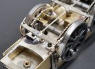
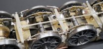
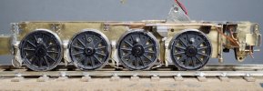
Together and apart many times to find and sort out little niggles and clearances. Eventually it all fits together and works. Here it is with the foot plate and cab just dropped in position. Very carefully applied medium strength thread lock is necessary to prevent some of the small threaded fasteners unscrewing when in motion.


Just to amuse myself I put together a short video of the valve gear of the loco in motion on the test track. I'd felt an urge to learn a bit of Adobe Premiere Pro and this seemed like a good enough excuse. Turned out to be a huge distraction and I haven't done any actual modelling for a couple of weeks. The sound isn't DCC sound (no sound decoder fitted), but odd sounds scraped off recordings and other videos. Genuine WD clanks! It's not Spielberg but it was fun and I've learned a lot in doing it. Can't get anything to upload to You Tube at the moment, but no problems with Vimeo...
In other news, the steel springs, although theoretically correct, just weren't workable. I found it impossible to get the loco to sit straight and it always felt as if the springs were too stiff. In the end I substituted them with springs made from phosphor bronze wire, which allowed the loco to sit down more comfortably. There's still a workable amount of suspension travel and it feels less 'bouncy'.
Thinking ahead to brake gear. Having brass brake shoes always seems electrically perilous to me. So far as I can tell the WD used exactly the same pattern brake shoes as the Stanier 8F. I used the CAD model of the brake shoe that I created for the 7mm 8F and scaled it to 4mm (I suppose that's called 'leveraging the design asset' in work speak). To make a 3D print reasonably economical I cloned the brake shoe up to twenty sets of eight shoes. More brake shoes there than I'll ever use in this lifetime.


In the end I had them printed by Shapeways. Certainly not the cheapest, but you always get a consistently good quality if you stick to their design guidelines, which I haven't always found to be the case with 'bloke in a shed' type suppliers. Came out pretty well. You can just see some layering on the close up photo, but that'll be removed with a lick of fine wet & dry.


Together and apart many times to find and sort out little niggles and clearances. Eventually it all fits together and works. Here it is with the foot plate and cab just dropped in position. Very carefully applied medium strength thread lock is necessary to prevent some of the small threaded fasteners unscrewing when in motion.

Just to amuse myself I put together a short video of the valve gear of the loco in motion on the test track. I'd felt an urge to learn a bit of Adobe Premiere Pro and this seemed like a good enough excuse. Turned out to be a huge distraction and I haven't done any actual modelling for a couple of weeks. The sound isn't DCC sound (no sound decoder fitted), but odd sounds scraped off recordings and other videos. Genuine WD clanks! It's not Spielberg but it was fun and I've learned a lot in doing it. Can't get anything to upload to You Tube at the moment, but no problems with Vimeo...
In other news, the steel springs, although theoretically correct, just weren't workable. I found it impossible to get the loco to sit straight and it always felt as if the springs were too stiff. In the end I substituted them with springs made from phosphor bronze wire, which allowed the loco to sit down more comfortably. There's still a workable amount of suspension travel and it feels less 'bouncy'.
Thinking ahead to brake gear. Having brass brake shoes always seems electrically perilous to me. So far as I can tell the WD used exactly the same pattern brake shoes as the Stanier 8F. I used the CAD model of the brake shoe that I created for the 7mm 8F and scaled it to 4mm (I suppose that's called 'leveraging the design asset' in work speak). To make a 3D print reasonably economical I cloned the brake shoe up to twenty sets of eight shoes. More brake shoes there than I'll ever use in this lifetime.


In the end I had them printed by Shapeways. Certainly not the cheapest, but you always get a consistently good quality if you stick to their design guidelines, which I haven't always found to be the case with 'bloke in a shed' type suppliers. Came out pretty well. You can just see some layering on the close up photo, but that'll be removed with a lick of fine wet & dry.


Last edited:
michael mott
Western Thunderer
Some really fine and fiddly work. Love the video of the motion, the sound effects really made it seem real.
Michael
Michael
Boyblunder
Western Thunderer
Absolutely agree about avoiding shorts caused by metal brake blocks, for 7mm vehicles I have been using some Off The Rails brake blocks which are for sale on Shapeways.
richard carr
Western Thunderer
Ian
I love the video, the sound is excellent, all that lovely clanking.
Richard
I love the video, the sound is excellent, all that lovely clanking.
Richard
Bradwell WD 2-8-0 - Brakes that really do bring you to a stop...
Ian_C
Western Thunderer
...but for the wrong reason!
After the valve gear I decided to have a go at the brakes. Cutting parts from the etch for the first time in ages felt like progress. It's a bit of a fiddle because the brake hanger brackets have to be made up from some small parts. Two etched parts, both with push through rivets, one with a double bend, and a length of 0.7 mm diameter brass wire.

Bradwell suggests making them up before soldering them into position on the chassis. I couldn't imagine being able to solder them to the chassis without unsoldering the brackets themselves, so I elected to silver solder the brackets . Here's a pair assembled around a length of wire which is pressed into a hole drilled in the heat proof block. The cruddy stuff is a tiny amount of silver solder paste before being heated. You have to be careful with the flame on small parts as it's easy to overheat them. I managed to melt one, so a replacement had to be made from scratch.

These are the brackets silver soldered before cleaning up. Well, the one bottom right has been cleaned up already.

All cleaned up. A short length of wire is left projecting from the back to locate in the holes in the chassis sides. You'll see that a gap has been cut in the wire between the inner and outer legs of the bracket. That is to enable the brake hanger to be slid up into the gap and hooked onto the wire stub. That way the whole brake sub assembly can be fitted and removed with out needing fasteners.

Here's the brake rigging beneath then loco that connects the brake hangers to the brake cylinder beneath the cab. Straightforward N/S etch and solder. A little simplified but you'll not see much of it.

The brakes are made up by filing off the outline of the brake blocks from the etched hangers. The blocks are pinned to the hangers with short lengths of 0.5 mm wire.

This shows a bracket located on the chassis.

And here's where it all goes wrong. You can see that the bracket is long enough to contact the connecting rods. No amount of finessing is going to sort that out. The only solution is to make shorter brackets. And since I silver soldered them together there's no chance of unsoldering them to recover some of the parts . Not sure I'm in the mood for making eight of these from scratch at the moment.

After the valve gear I decided to have a go at the brakes. Cutting parts from the etch for the first time in ages felt like progress. It's a bit of a fiddle because the brake hanger brackets have to be made up from some small parts. Two etched parts, both with push through rivets, one with a double bend, and a length of 0.7 mm diameter brass wire.

Bradwell suggests making them up before soldering them into position on the chassis. I couldn't imagine being able to solder them to the chassis without unsoldering the brackets themselves, so I elected to silver solder the brackets . Here's a pair assembled around a length of wire which is pressed into a hole drilled in the heat proof block. The cruddy stuff is a tiny amount of silver solder paste before being heated. You have to be careful with the flame on small parts as it's easy to overheat them. I managed to melt one, so a replacement had to be made from scratch.

These are the brackets silver soldered before cleaning up. Well, the one bottom right has been cleaned up already.

All cleaned up. A short length of wire is left projecting from the back to locate in the holes in the chassis sides. You'll see that a gap has been cut in the wire between the inner and outer legs of the bracket. That is to enable the brake hanger to be slid up into the gap and hooked onto the wire stub. That way the whole brake sub assembly can be fitted and removed with out needing fasteners.

Here's the brake rigging beneath then loco that connects the brake hangers to the brake cylinder beneath the cab. Straightforward N/S etch and solder. A little simplified but you'll not see much of it.
The brakes are made up by filing off the outline of the brake blocks from the etched hangers. The blocks are pinned to the hangers with short lengths of 0.5 mm wire.

This shows a bracket located on the chassis.

And here's where it all goes wrong. You can see that the bracket is long enough to contact the connecting rods. No amount of finessing is going to sort that out. The only solution is to make shorter brackets. And since I silver soldered them together there's no chance of unsoldering them to recover some of the parts
 . Not sure I'm in the mood for making eight of these from scratch at the moment.
Gadgie
Western Thunderer
I’ve spent this weekend assembling the tender brake gear for my Bradwell WD. It has been a real pleasure. Everything has gone together nicely, so I was surprised and saddened to read your update. Looks grim, and deeply aggravating. Loco brakes are a way off for me, but I’m very grateful in advance for the heads up that this aspect of clearances may be a problem, and I’m sure you will find a way round it.
Richard.
Richard.
Ian_C
Western Thunderer
Bradwell WD 2-8-0 - loco brake gear completed
It's been a while since I accomplished much at the modelling bench. I go through phases when I look at the workbench and it doesn't grab my interest. There are easier ways to get a dopamine hit than working through loco brake gear. Sometimes I just want to shake the box and have the kit assemble itself. It didn't help that my son gave me the Haynes manual for the Fairchild/Republic A 10 Thundebolt for Christmas (yes you can get the Haynes manual for that, although I don't think it qualifies you as ground crew once you've read it). That got me looking at 1/48 scale A-10 kits. Huge distraction. Haven't ordered a kit, but the seed has been planted, and I do rather enjoy Heather K's aeronautical diversions, so you never know...
The way around the brake hanger to coupling rod clearance problem was 'simply' to make some shorter hanger brackets. The only drawing I have of the WD doesn't show the hanger brackets so I've no idea how far they stick out from the chassis on the prototype. The etched brackets in the kit project about 2.8mm from the chassis. Careful measuring of the coupling rod position suggested that I could make it work with brackets projecting no more that 2.2mm. How I went about that is shown below.
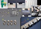
1- As usual a bracket was modelled on CAD to work out the detail. I decided to make the yellow part just butt joint to the green base so its horizontal leg could be made over length and adjusted after bending. No chance of bending to exactly the right length each time. Since it was to be silver soldered that butt joint should be strong enough to survive the subsequent wrestling with the brake gear.
2 - Ten sets of bracket parts were marked out on some scraps of 0.3mm N/S. Ten because you can chuck away the worst two! Yes, I used callipers to scribe the lines, heresy, heresy.
3 - And to make sure I didn't get the marking, rivet and hole positions wrong I made a spreadsheet and printed the dimensions out in a table. Check before marking and tick them off as you go.
4 - Here's the venerable GW rivet press actually doing what it was designed to do. The material is lined up in the clamp, the first rivet position found, then the graduated cross slide twirly knob is set to zero and off you go by the numbers. The leadscrew is a length of M6 x 1.0 all thread and you'd think that would be reasonably accurate, but getting across to the last few rivet positions I could see it was drifting away from the marked rivet positions slightly. A small adjustment made to get the last few rivets in the right place.
5 - Here they are with rivets formed and holes drilled. The holes were drilled 0.7mm to be a close fit on 0.7mm brass wire.
6 - The parts were cut out with a piercing saw, filed to size and shape, bent and adjusted to length. Fiddly work, particularly when you're trying to hold them in the vice device and not squash the rivets. One day I might make a finer instrument maker's vice for just this kind of work. One day...
7 - All silver soldered up on short lengths of 0.7mm brass wire. The downside of silver soldering is that all the material is wonderfully annealed and you have to be careful not to bend things when you do further work.
8 - Here they are finished and ready to fit to the chassis. A small wire spigot is left on the back of the bracket to locate in the holes etched for the purpose in the chassis side plates. The wire spanning the bracket has a short section cut away to allow the brake hangers to be inserted ( illustrated in a following photo).
9 - Soldered to the chassis using 179 degree solder and a mighty but brief thunderbolt from the RSU. You'd struggle with this if you'd soft soldered the brackets together. Worth noting at this point that the wheel flanges come really close to these hangers, and that's using a Gibson P4 wheel profile. You may be in trouble here with EM or OO wheels and will probably have to resort to some flange reduction.
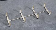
Assembling all this lot was the devil's own work. Much gumption used up to get everything postioned. The brake shoes were chamfered quite heavily on the back edges to provide adequate side play for the wheels on axles 2 and 3 (yes, if I'd thought ahead |I could have designed them to be printed with a chamfer already included, but then they'd be handed). The brake blocks were left free to pivot on initial assembly so they could align to the wheel tyres when finally positioned. When all was in position the lower end of hangers were soldered to the brake cross beams. The soldered sub-assembly was tweaked to get the brake blocks in position on the wheels and then the blocks were fixed to the hangers with a tiny blob of low viscosity cyano which capillaries into the joint and pivot and gums everything up nicely without leaving much of a trace.
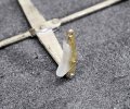
Here's a cruel close up of a hanger and brake block. The block does have nice crisp outside edges, but all shows as a pale blob in the photo.
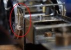
Here's a close up showing how the brake hangers clip into the hanger brackets. The brake gear is thus removable without fasteners or complication, just olympic standard fine tweezer work. That was Mr Bradwell's design intent, and I have to say it works very well in the end.

That's what I ended up with. Brake blocks that are correct to prototype shape and size, non-conducting, close to wheels, adequate side clearance and removable without surgery. Epic struggle but worth it in the end. I guess this is what you sign up for if you want model locos like this in P4.
P.S.- I think I'll get used to the new format Western Thunder, although I do miss the 'title bar' for your posts if that's what it was called.
It's been a while since I accomplished much at the modelling bench. I go through phases when I look at the workbench and it doesn't grab my interest. There are easier ways to get a dopamine hit than working through loco brake gear. Sometimes I just want to shake the box and have the kit assemble itself. It didn't help that my son gave me the Haynes manual for the Fairchild/Republic A 10 Thundebolt for Christmas (yes you can get the Haynes manual for that, although I don't think it qualifies you as ground crew once you've read it). That got me looking at 1/48 scale A-10 kits. Huge distraction. Haven't ordered a kit, but the seed has been planted, and I do rather enjoy Heather K's aeronautical diversions, so you never know...
The way around the brake hanger to coupling rod clearance problem was 'simply' to make some shorter hanger brackets. The only drawing I have of the WD doesn't show the hanger brackets so I've no idea how far they stick out from the chassis on the prototype. The etched brackets in the kit project about 2.8mm from the chassis. Careful measuring of the coupling rod position suggested that I could make it work with brackets projecting no more that 2.2mm. How I went about that is shown below.

1- As usual a bracket was modelled on CAD to work out the detail. I decided to make the yellow part just butt joint to the green base so its horizontal leg could be made over length and adjusted after bending. No chance of bending to exactly the right length each time. Since it was to be silver soldered that butt joint should be strong enough to survive the subsequent wrestling with the brake gear.
2 - Ten sets of bracket parts were marked out on some scraps of 0.3mm N/S. Ten because you can chuck away the worst two! Yes, I used callipers to scribe the lines, heresy, heresy.
3 - And to make sure I didn't get the marking, rivet and hole positions wrong I made a spreadsheet and printed the dimensions out in a table. Check before marking and tick them off as you go.
4 - Here's the venerable GW rivet press actually doing what it was designed to do. The material is lined up in the clamp, the first rivet position found, then the graduated cross slide twirly knob is set to zero and off you go by the numbers. The leadscrew is a length of M6 x 1.0 all thread and you'd think that would be reasonably accurate, but getting across to the last few rivet positions I could see it was drifting away from the marked rivet positions slightly. A small adjustment made to get the last few rivets in the right place.
5 - Here they are with rivets formed and holes drilled. The holes were drilled 0.7mm to be a close fit on 0.7mm brass wire.
6 - The parts were cut out with a piercing saw, filed to size and shape, bent and adjusted to length. Fiddly work, particularly when you're trying to hold them in the vice device and not squash the rivets. One day I might make a finer instrument maker's vice for just this kind of work. One day...
7 - All silver soldered up on short lengths of 0.7mm brass wire. The downside of silver soldering is that all the material is wonderfully annealed and you have to be careful not to bend things when you do further work.
8 - Here they are finished and ready to fit to the chassis. A small wire spigot is left on the back of the bracket to locate in the holes etched for the purpose in the chassis side plates. The wire spanning the bracket has a short section cut away to allow the brake hangers to be inserted ( illustrated in a following photo).
9 - Soldered to the chassis using 179 degree solder and a mighty but brief thunderbolt from the RSU. You'd struggle with this if you'd soft soldered the brackets together. Worth noting at this point that the wheel flanges come really close to these hangers, and that's using a Gibson P4 wheel profile. You may be in trouble here with EM or OO wheels and will probably have to resort to some flange reduction.

Assembling all this lot was the devil's own work. Much gumption used up to get everything postioned. The brake shoes were chamfered quite heavily on the back edges to provide adequate side play for the wheels on axles 2 and 3 (yes, if I'd thought ahead |I could have designed them to be printed with a chamfer already included, but then they'd be handed). The brake blocks were left free to pivot on initial assembly so they could align to the wheel tyres when finally positioned. When all was in position the lower end of hangers were soldered to the brake cross beams. The soldered sub-assembly was tweaked to get the brake blocks in position on the wheels and then the blocks were fixed to the hangers with a tiny blob of low viscosity cyano which capillaries into the joint and pivot and gums everything up nicely without leaving much of a trace.

Here's a cruel close up of a hanger and brake block. The block does have nice crisp outside edges, but all shows as a pale blob in the photo.

Here's a close up showing how the brake hangers clip into the hanger brackets. The brake gear is thus removable without fasteners or complication, just olympic standard fine tweezer work. That was Mr Bradwell's design intent, and I have to say it works very well in the end.

That's what I ended up with. Brake blocks that are correct to prototype shape and size, non-conducting, close to wheels, adequate side clearance and removable without surgery. Epic struggle but worth it in the end. I guess this is what you sign up for if you want model locos like this in P4.
P.S.- I think I'll get used to the new format Western Thunder, although I do miss the 'title bar' for your posts if that's what it was called.
Last edited:
adrian
Flying Squad
maybe you are referring to threadmarks which you've used extensively in this thread - certainly hope so. I've now included this addon and imported all the threadmarks from the older version just this evening so you may not have seen it yet. It is now available in this thread with a few nice new features try "Reader mode"although I do miss the 'title bar' for your posts if that's what it was called.
so here for the announcement
Forum upgrade - information and queries.
I really like the reader mode, works really well on the Polsarrett thread. Nice.
www.westernthunder.co.uk
Bradwell WD 2-8-0 - injectors (welcome back threadmarks)
Ian_C
Western Thunderer
On to the injectors. Yup, you can get a whole chapter out of the injectors. The prototype was equipped with two identical Davies & Metcalfe No 11 injectors RH pattern, fitted with No10 cones. The Scalefour Society says I should be 'getting it all right', but I guess I can still keep my membership if I don't bother with the cones. The kit was supplied with a couple of very nice brass injector castings that only needed the pipe holes drilling a bit deeper. Squinting at the GA drawing suggests that the injector pipework was of two diameters that scale to approximately 0.7mm and 0.8mm. My horde of copper wire has been mostly looted from electrical cable and naturally none of it was a suitable size. Amazon to the rescue of course, and it is possible to buy small reels of 0.7mm and 0.8mm copper wire for making low rent jewellery.
First job was to make up the bracket that supports the injectors. There are half etched rivets to represent the injector fixing bolts, but they look a bit too smooth and rivety whereas the bolt heads are distinct on most photos. They were drilled through 0.5mm and stubs of brass wire were silver soldered in place and filed down. Definitely more bolty now. The injector castings were soldered to the bracket with a high melt solder.
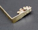
The etched bracket spans the chassis and it's a bit goofy and bendy, so Bradwell advises reinforcing with wire on the inside. You can sort of see the wire trying to keep out of focus in this photo showing the inside of the injector.
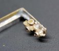
And here it is ready to fit to the chassis.
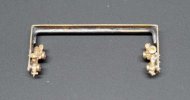
I also added to the side of the chassis the triangular brackets that support the footplate. Now there are things sticking out of each side of the chassis it's more difficult to work on the chassis and easy to bend the things. The front brackets, just behind the cylinders, are particularly vulnerable with a big hole etched through them. But not to worry, as I found out that it's impossible to fit the cylinders to the chassis with these brackets in place, so off they came again. I'm not sure I'll miss them in that dark and filthy corner. Maybe I'll fix them to the underside of the footplate instead. We'll see...
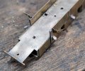
The injector steam pipes from the cab end up level with the chassis top surface and terminate in thin air. To give them some support I added two plates (green arrows) from scrap etched. I'm confident you'll not see these plates under the footplate. The pipes passed through holes in the plates and were cut and filed flush after soldering. The boiler feed pipes running forward along each side beneath the edge of the footplate are very visible, but the problem is what to fix them to. If you fit them to the footplate the end connecting to the injector is unsupported. And if you fit them to the injector you can't secure them to the footplate because that's part of the boiler assembly and has to be removable from the chassis. My solution was to add some more small pieces of scrap etch (red arrows) to reinforce the weedy triangular brackets on the side of the chassis and support the injector pipes. The beautifully crisp white metal sand box castings were epoxied to the chassis at this point. There's no positive location for them on the chassis so take care to position them accurately.
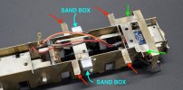
Here are the feed pipes soldered to the new brackets. The pipes actually dive inside the motion bracket assembly on their way forwards, but again they can't do this the model as they would make it impossible to remove the cylinder and motion assembly from the chassis. I chose to terminate the pipes short of the motion bracket and gamble that it won't be noticeable under the footplate. They do end in thin air but they're close enough to the chassis not to be very vulnerable. I hope.
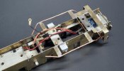
Here's the injector pipe work seen from below. I should mention at this point that the copper wire, although appearing to be plain wire, actually has a thin and very tenacious coating of something. That's a pain because it all has to be removed before soldering. Whatever it is it's heat proof, solvent proof and really takes some shifting with an abrasive pad. You can also see the diagonal stays bracing the injector brackets to the chassis. The instructions have a couple of decent sketches to clarify the injector pipe routing.
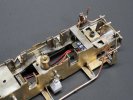
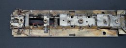
The RH side view. The injector overflow pipe on this side of a WD has two variants. There's one that simply exits the injector and has a short downwards pointing section. And there's this one that loops back under the injector and is secured to the injector bracket with a small strap. This type seems to be the more common on BR locos. I've just noticed that I've missed two small straps that secure the pipe to the footplate. A couple of strips of brass shim sweated to the pipe should fix that.
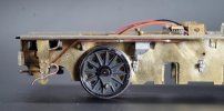
LH side, also missing the support straps. The pipe neatly hides its support brackets.
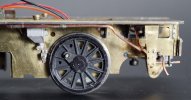
I couldn't resist turning up a couple of tiny doodads to represent the pipe unions.
Next job is the sanding gear, which is bound to be a struggle.
First job was to make up the bracket that supports the injectors. There are half etched rivets to represent the injector fixing bolts, but they look a bit too smooth and rivety whereas the bolt heads are distinct on most photos. They were drilled through 0.5mm and stubs of brass wire were silver soldered in place and filed down. Definitely more bolty now. The injector castings were soldered to the bracket with a high melt solder.

The etched bracket spans the chassis and it's a bit goofy and bendy, so Bradwell advises reinforcing with wire on the inside. You can sort of see the wire trying to keep out of focus in this photo showing the inside of the injector.

And here it is ready to fit to the chassis.

I also added to the side of the chassis the triangular brackets that support the footplate. Now there are things sticking out of each side of the chassis it's more difficult to work on the chassis and easy to bend the things. The front brackets, just behind the cylinders, are particularly vulnerable with a big hole etched through them. But not to worry, as I found out that it's impossible to fit the cylinders to the chassis with these brackets in place, so off they came again. I'm not sure I'll miss them in that dark and filthy corner. Maybe I'll fix them to the underside of the footplate instead. We'll see...

The injector steam pipes from the cab end up level with the chassis top surface and terminate in thin air. To give them some support I added two plates (green arrows) from scrap etched. I'm confident you'll not see these plates under the footplate. The pipes passed through holes in the plates and were cut and filed flush after soldering. The boiler feed pipes running forward along each side beneath the edge of the footplate are very visible, but the problem is what to fix them to. If you fit them to the footplate the end connecting to the injector is unsupported. And if you fit them to the injector you can't secure them to the footplate because that's part of the boiler assembly and has to be removable from the chassis. My solution was to add some more small pieces of scrap etch (red arrows) to reinforce the weedy triangular brackets on the side of the chassis and support the injector pipes. The beautifully crisp white metal sand box castings were epoxied to the chassis at this point. There's no positive location for them on the chassis so take care to position them accurately.

Here are the feed pipes soldered to the new brackets. The pipes actually dive inside the motion bracket assembly on their way forwards, but again they can't do this the model as they would make it impossible to remove the cylinder and motion assembly from the chassis. I chose to terminate the pipes short of the motion bracket and gamble that it won't be noticeable under the footplate. They do end in thin air but they're close enough to the chassis not to be very vulnerable. I hope.

Here's the injector pipe work seen from below. I should mention at this point that the copper wire, although appearing to be plain wire, actually has a thin and very tenacious coating of something. That's a pain because it all has to be removed before soldering. Whatever it is it's heat proof, solvent proof and really takes some shifting with an abrasive pad. You can also see the diagonal stays bracing the injector brackets to the chassis. The instructions have a couple of decent sketches to clarify the injector pipe routing.


The RH side view. The injector overflow pipe on this side of a WD has two variants. There's one that simply exits the injector and has a short downwards pointing section. And there's this one that loops back under the injector and is secured to the injector bracket with a small strap. This type seems to be the more common on BR locos. I've just noticed that I've missed two small straps that secure the pipe to the footplate. A couple of strips of brass shim sweated to the pipe should fix that.

LH side, also missing the support straps. The pipe neatly hides its support brackets.

I couldn't resist turning up a couple of tiny doodads to represent the pipe unions.

Next job is the sanding gear, which is bound to be a struggle.
Bradwell WD 2-8-0 - sanding gear
Ian_C
Western Thunderer
'Sanding gear' isn't an anagram of 'gnashing rage', although it should be. I had to have two laps around the sanding gear to arrive at a workable solution.
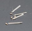
The brackets that support the sanding gear on the WD are a delicate confection of strips and plates and angle iron. It's beyond me to model that lot to scale in 4mm, and it would not be sufficiently robust to survive handling during the rest of the build or in use. So what follows is a bit of approximation and bodgery. After some staring and head scratching I decided to make the sanding pipe brackets from strips of 0.4mm N/S, 1mm wide. The sand pipes scale to about 0.5mm and are from brass wire. Some tiny brass turnings represent the pipe fitting near the support brackets.
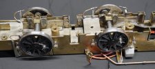
The pipes and brackets were eventually fiddled into place and soldered to the inside of the chassis. At that point I was congratulating myself on how relatively easy it had been, until I realised that that it would be impossible to fit the brake gear because the cross beams pass through the gap between sanding pipe and support bracket. Also with the pipes in position it proved impossible to remove the 3rd axle from the chassis. Oh well! Unsolder it all and think again.
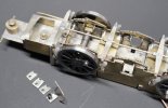
The solution I adopted was to make the two forward most pairs of sanding pipes and brackets individual, removable parts that could be slipped over the brake beams and fixed by a small screw. The rear sanding pipes on the 3rd axle don't get tangled in the brake gear so they can stay as they are. More little brackets from scraps of N/S. The screws are M1.2 x 0.25. These small steel screws are dirt cheap on Ebay or Amazon. You can get a selection box with hundreds of the blighters from M1.2 up to M2.5 for not much. I find these small Philips head screws much easier to work with than the typical B.A. slotted head screws.
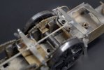
One was made up and fitted to test the theory. The hole was marked on the chassis and tapped M1.2. Luckily you can just get the screwdriver past the brake beam and onto the screw head.
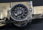
The pipes pass pretty close beneath the brake gear. I've left the end of the pipes a little further away from the wheels than is prototypical in order to reduce the risk of electrical shorts due to suspension movement and side play. Doesn't look too bad.
The brake gear is fitted first before the sanding pipes. Here's the first axle with everything in place.
And here's the third axle.
And here's how it looks when it's all together. Enough authentic clutter down there to fill the gaps and attract the obligatory WD coating of oily filth. The odd looking vertical pipe in front of the injector is the vacuum pipe and water trap, a rather splendid little brass casting being supplied with the kit.
What's next I wonder? Maybe the AWS gear.

The brackets that support the sanding gear on the WD are a delicate confection of strips and plates and angle iron. It's beyond me to model that lot to scale in 4mm, and it would not be sufficiently robust to survive handling during the rest of the build or in use. So what follows is a bit of approximation and bodgery. After some staring and head scratching I decided to make the sanding pipe brackets from strips of 0.4mm N/S, 1mm wide. The sand pipes scale to about 0.5mm and are from brass wire. Some tiny brass turnings represent the pipe fitting near the support brackets.

The pipes and brackets were eventually fiddled into place and soldered to the inside of the chassis. At that point I was congratulating myself on how relatively easy it had been, until I realised that that it would be impossible to fit the brake gear because the cross beams pass through the gap between sanding pipe and support bracket. Also with the pipes in position it proved impossible to remove the 3rd axle from the chassis. Oh well! Unsolder it all and think again.

The solution I adopted was to make the two forward most pairs of sanding pipes and brackets individual, removable parts that could be slipped over the brake beams and fixed by a small screw. The rear sanding pipes on the 3rd axle don't get tangled in the brake gear so they can stay as they are. More little brackets from scraps of N/S. The screws are M1.2 x 0.25. These small steel screws are dirt cheap on Ebay or Amazon. You can get a selection box with hundreds of the blighters from M1.2 up to M2.5 for not much. I find these small Philips head screws much easier to work with than the typical B.A. slotted head screws.

One was made up and fitted to test the theory. The hole was marked on the chassis and tapped M1.2. Luckily you can just get the screwdriver past the brake beam and onto the screw head.

The pipes pass pretty close beneath the brake gear. I've left the end of the pipes a little further away from the wheels than is prototypical in order to reduce the risk of electrical shorts due to suspension movement and side play. Doesn't look too bad.

The brake gear is fitted first before the sanding pipes. Here's the first axle with everything in place.

And here's the third axle.

And here's how it looks when it's all together. Enough authentic clutter down there to fill the gaps and attract the obligatory WD coating of oily filth. The odd looking vertical pipe in front of the injector is the vacuum pipe and water trap, a rather splendid little brass casting being supplied with the kit.
What's next I wonder? Maybe the AWS gear.
Last edited:
john lewsey
Western Thunderer
That is very, very nice work
Bradwell WD 2-8-0 - big bits coming together at last
Ian_C
Western Thunderer
With most of the difficult work out of the way (and yes, doubtless I'll eat my words a few more posts down the line) I figured it was time to put the upper works together.
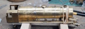
There's provision to fix the cab to the footplate and the back of the firebox with screws. That's handy, as it can be accurately located and used to get the exact position of the boiler without having to fix it permanently in place. Some fettling was required to make the smokebox sit down nicely on the saddle casting. The steam pipe exit location on the smoke box didn't quite line up with the corresponding holes for the steam pipes in the footplate. Maybe only half a mm but enough to make them look wrong when seen broadside on. I never did fix the smokebox into the front of the boiler as it's a perfect push fit and I thought it would be better to leave some adjustment there, both longitudinal and rotational. I carefully filed back the front edge of the boiler until the smokebox was far enough back for the steam pipes to line up. I didn't fancy trying to solder the smokebox to the saddle so I fixed it in position with epoxy. The elastic bands hold it tightly together while the epoxy cures. The epoxy also neatly fills any gap between smokebox and saddle and the surplus can be easily scraped away when cured. The firebox was easy enough to tack to the footplate just in front of the cab. Still needed the 100W iron as there's plenty of material to soak the heat away. There's no turning back now! You can see the mess I made of the firebox wrapper just in front of the washout covers. I've filled the divots with low melt solder and smoothed it the best I can. The reflected light makes it look worse than it is and I'm hoping that the kink in the handrail here plus some weathering will disguise it. Hoping...
The steam pipes were gently filed to a tidy fit and soldered in place at the footplate end only. No point trying to solder them to the smokebox as it would be a difficult joint and a devil of a job to clean up any stray solder. As is tradition enough parts were flung together to get an idea of how the loco is shaping up. The tender will be closer coupled than this when it's properly assembled. A lot of detail to add, but it's definitely a WD now.

Gently frosted leaves this morning. Not spring here just yet.

There's provision to fix the cab to the footplate and the back of the firebox with screws. That's handy, as it can be accurately located and used to get the exact position of the boiler without having to fix it permanently in place. Some fettling was required to make the smokebox sit down nicely on the saddle casting. The steam pipe exit location on the smoke box didn't quite line up with the corresponding holes for the steam pipes in the footplate. Maybe only half a mm but enough to make them look wrong when seen broadside on. I never did fix the smokebox into the front of the boiler as it's a perfect push fit and I thought it would be better to leave some adjustment there, both longitudinal and rotational. I carefully filed back the front edge of the boiler until the smokebox was far enough back for the steam pipes to line up. I didn't fancy trying to solder the smokebox to the saddle so I fixed it in position with epoxy. The elastic bands hold it tightly together while the epoxy cures. The epoxy also neatly fills any gap between smokebox and saddle and the surplus can be easily scraped away when cured. The firebox was easy enough to tack to the footplate just in front of the cab. Still needed the 100W iron as there's plenty of material to soak the heat away. There's no turning back now! You can see the mess I made of the firebox wrapper just in front of the washout covers. I've filled the divots with low melt solder and smoothed it the best I can. The reflected light makes it look worse than it is and I'm hoping that the kink in the handrail here plus some weathering will disguise it. Hoping...

The steam pipes were gently filed to a tidy fit and soldered in place at the footplate end only. No point trying to solder them to the smokebox as it would be a difficult joint and a devil of a job to clean up any stray solder. As is tradition enough parts were flung together to get an idea of how the loco is shaping up. The tender will be closer coupled than this when it's properly assembled. A lot of detail to add, but it's definitely a WD now.

Gently frosted leaves this morning. Not spring here just yet.

Threadmarks
View all 176 threadmarks
Reader mode
Reader mode
