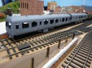
Mick's workbench ( easybuild 7mm Craven class 105 dmu )

Hi Everybody
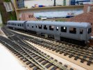
Just joined the forum I have just started this build and wondered if any of you have built an easybuild kit I found the progress is very slow but I think i am getting there, I have also made a few changes i will upload some photoe's as i progress,
.
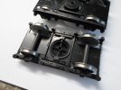
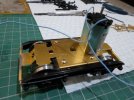
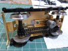
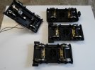
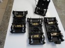
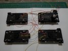
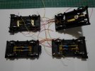
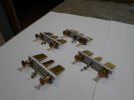
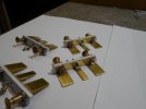
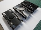
some photoes of the bogies to start with,


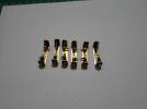
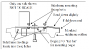
I purchased some slater's plunger pickups to mount under the bogies by folding up a channel section in brass.and mounting them under the chassis.

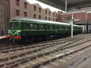
This craven unit is for my o gauge layout which is modelled to the stour valley line at Sudbury and Long melford in suffolk which is where i grew up and often travelled on a class 105 or a derby lightweight.
MickSAM_1258.JPGSAM_1259.JPGSAM_1260.JPGSAM_1261.JPGSAM_1279.JPGSAM_1280.JPGSAM_1281.JPG
 
Last edited:

daifly

Western Thunderer
Hi MIck

One of us says to all new members - PLEASE post full size images and not thumbnails. You can edit the offending photos by clicking on the 'Edit' option at the bottom of your post. Then, for each image, click on the '+Full" option as shown here:
Screenshot 2022-07-20 at 19.54.38.png
Thanks

Dave
 
Hi Dave Changed all photoes to full but now i have 2 lots of photoe's can i just delete the thumbnails or does that make things worse.Plus things are in the wrong order.
Mick
 

daifly

Western Thunderer
Hi Mick

No need to delete the thumbnails. They won't appear if you've posted them full size. You can edit them by jgoing back to 'Edit" and then ust dragging and dropping within your post as you want them. You can also add captions before or after them to give them context.

Dave
edited to add - our posts crossed! Glad you're sorted.
 

Bill Campbell

Western Thunderer
Hi Mick

I have built one of these:

IMG_0956.JPG

It's a bit like building a loco kit and two coach kits at the same time!

The wheels in your pictures look as though they have not been blackened. I mention this as the wheels I have were supplied blackened and I had to remove a circular strip of blackening on the back of each wheel to get electrical continuity. My 105 picks up from all unpowered wheels using phosphor bronze strip. I have two operational jumper cables between the vehicles - a 2-way for track pickup and a 3-way for lights.

If there is anything specific you want to know about as you construct yours feel free to ask.

Regards.
 
Hi Bill Thanks for your interest its my first time with easybuild not sure where the word easy comes from maybe i will feel differently when i get into it more, seam to spend a lot of time reading the instructions and online looking for details rather than following kit plans which i am more use to,
The wheels sets were plan steel no coating but i did mask the backs and the tyres before spraying matt black hope to wire these up today, Nice idea on the under floor centre channel some where to run cables,

That unit of yours looks great nice job is it dcc and sound which is the way i want to go,
After wiring I'll have a go at fitting the door handles to the body sides.
Mick
 

Bill Campbell

Western Thunderer
Hi Mick

Mine is DCC with sound - 2 speakers for 2 engines - and a stay alive. The luggage compartment houses the decoder and capacitor.

DMBS interior with passengers.JPG

Think long and far ahead about the construction sequence. I completed all other work on the body before fitting hinges (before painting) and door handles (after painting).

You will find that a considerable amount of work is required to blend the ends and cab roofs to the body and roof profiles so there is a lot of messy filling and smoothing work to be done before the body gets anywhere near the painting stage.

You should also think carefully about the method you plan to use to secure the body to the floor/chassis - that's not a criticism of the suggested method but more personal preference - I did not want to use the long bolts as they would be visible in the finished model. You may be able to see from the photo of the DMBS interior that I used sub-floors for the seats as the top of the chassis is not level. You will also find that the seat legs are too long - I shortened mine so that the seats sit at the correct height relative to the windows. I scratch built the seats for the first class compartment in the DTCL.

DTCL interior with passengers.JPG

While I remember - check the ventilator positions using photographs - particularly the toilet area of the DTCL and the water filler pipes. I don't think the instructions mention the alarm gear at the non-cab ends of each vehicle - a bit of scratch building is needed.

Depending on period you will need to consider which exhaust setup to use - unless they have been updated the instructions are very vague.

Underneath the DBMS the instructions do not mention the torque convertor or the drive shaft from the gearbox - another detail to watch out for.

The simple bellows gangway supplied is not very prototypical - I used a set of scissors gangways from CPL - not quite right but much better appearance. I used Kadee couplers between the vehicles but I would now go for MagClic - I had already gone for the Kadees before MagClics came on the market.

Railcar.co.uk has some useful information and photos.

Regards.
 
Last edited:
Bill Some great points there to think about thankyou, I did look at the door handles and thought no i could'nt have all those sticking out while there is so much to do with the body sides i have cut them but i've put them in a little bag for later,
I agree with you i dont like the fixing bolts for the roof i have been following a class 101 build which uses floor straps fixed to the body bottom edge and bolted through the floor,
I noticed you have used kadee couplings all my stock is kadee.
The unit i have based mine on is no/ E53359 & E54122 which travelled all over east anglia and a visit to sudbury my local town.
Mick
 

Bill Campbell

Western Thunderer
Hi Mick

I have also used body cross members at floor level for fixing the body in place. These are arranged at the vestibules and the DBMS has an extra fixing just inside the end of the luggage compartment to give better support with the weight of the power bogie. I used short M4 screws with the cross members tapped for M4.

The reservation I now have about the Kadee couplers is that uncoupling the vehicles is tricky with the gangways in place as I have mounted the Kadees at buffer beam level.

Regards.
 
Hi Bill
Are the Kadee coupling really a problem how often do you split these units and the electric's as well I would think using a magnet would be a simple option to split.
One other thing on the power bogie why is my pivot hole over size at 6mm stead of 4mm is this something you found, I soldered a piece of brass in and drilled a 4mm hole.
Mick
 
Hi Ian
Thanks for the interest have a way to go before that but its an idea, These are heavy units and wondered if they would be powerfull enough for the job as I have said to bill is it a problem, Or do we test it and see.
Mick
 

Bill Campbell

Western Thunderer
Hi Bill
Are the Kadee coupling really a problem how often do you split these units and the electric's as well I would think using a magnet would be a simple option to split.
One other thing on the power bogie why is my pivot hole over size at 6mm stead of 4mm is this something you found, I soldered a piece of brass in and drilled a 4mm hole.
Mick
Hi Mick

I only separate the vehicles when removing from the layout - not while running. I have subsequently used the MagClics on gangwayed coaches and they are plenty strong enough for my train of 5 ex-LMS coaches. The nice thing about the MagClics is that they are easy to fit as they simply go into the existing coupling position in the buffer beam. They are just the right length for vehicle spacing as well. Kadees cannot be mounted below the buffer beam as their draft boxes would foul the bogies. It's not worth my while replacing the Kadees as a chunk of the buffer beam was removed to fit them.

Power bogie pivot - this is from page 8 - section 34 - of the instructions I have:

Screenshot 2022-07-22 at 13.47.33.png

You should have a brass top-hat insert for the power bogie pivot - this is not shown in the revised instructions for the later version of the power bogie (these may be on a separate sheet or download). The insert means that the pivot is not the threaded screw shaft and the screw can be done up tightly against the insert. In any case you will need to check the ride height of the chassis.

Regards.
 
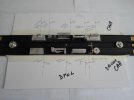
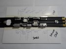
Hi This was my method for marking the under floor for all the components it took 3 goes to get it right trying to mark upside down and left to right but we got there, All is needed now is working out the pipework-exhaust-conduit etc,
On the DMBS I'm wondering if there needs to be any stiffeners round the motor cut out seems a bit flimsy with all this extra weight.
MickSAM_1290.JPGSAM_1291.JPG
 

SouthernFan Ian

Western Thunderer
Hi Ian
Thanks for the interest have a way to go before that but its an idea, These are heavy units and wondered if they would be powerfull enough for the job as I have said to bill is it a problem, Or do we test it and see.
Mick
Hello Mick,
A friend of mine has fitted Magiclik to some coaches and I was surprised how much force is required to disconnect them. I think they will be more than adequate for a two car DMU.
Regards,
Ian
 
Top