Phil's GW coach bodging

Phil O

Western Thunderer
Hi All

I have got around to starting to build Plymouth Area Auto Trailers Diag Q & R, these trailers are gangwayed together and so ran as a pair, there are several other diagrams, but these were the most numerous.

The Etches have come from Worsley Works. Great Western Railway - 4mm Scale GWR Coaches - GWR Locomotives

Diag Q.JPG

Diag Q etch

Diag R.JPG

Diag R etch

Sorry I don't have a photo of the revised end etches for the gangway end of these coaches.

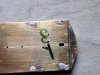
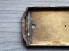
The first thing you will notice is that the floor end has square ends rather than forming an elongated hexagon.

My next post will show what I did, but it's now pub O'clock and I'm off for my first pint of the year.

Phil
 

Phil O

Western Thunderer
I scanned the drawing in the John Lewis book Great Western Auto Trailers and imported into Inkscape, I Then started another layer and drew a rectangle to the correct dimensions having checked the width of the floor etch and the drawing dimension and locked it, I then resized the scan to fit the rectangle and locked that. I marked the longitudinal Centre line on it in a new layer and added the line across the two corners of the outer end and printed it off. Using a pair of compasses I transferred the dimensions of the three components that make up the extension to the floor rectangle to to a sticky label, cut it out and stuck it on a piece of fret waste and cut it out. I then cut out the body end and folded it to suit the piece of floor and offered it up. At this point a lot of swearing ensued as the folded end did not reach the edge, I checked the dimension of my piece of floor, spot on to the etched floor and the drawing dimension, so I got me adjustable spanner, Boilermakers term for Vernier Callipers and measured the etched end and low it's 1mm narrower, "sh1t" no allowance has been made for folding the end. After an adjournment to the pub for some liquid deliberation, I decided I could live with the discrepancy and so upon return I marked the centreline down the floor on both sides and clamped a steel rule to the etch along the centreline and using dividers set to half the new floor width and scribed the line, repeat for the other half and filed the floor to the new width and amended the end extension, "Great", used that to create the other one. Using a bit more fret waste, I produced the buffer beam.

Auto 3.jpg

Note this picture is only a quick knock up for demonstration purposes and not what was fitted.

The two floor extensions were added to the original floor etch and a butt-strap added, I now cut out the gangwayed end and offered it up, more swearing ensued the "flat" portion of this end is slightly wider to facilitate the gangway. A further visit to the pub too cool down and reflect.
 

Phil O

Western Thunderer
OK, the floor is now sorted.

Auto 1.jpg

Auto 1.jpg

The ends marked to remind me which is which!

And the underside.

Auto 1.jpg

My thoughts then turned to the underpinnings, I had a talk with David Geen at a show and he agreed to provide me with underframe bits and bogies from his auto trailer kit, sadly this resource is no longer an option, due to David's retirement. Thoughts also turned to compartment bulkheads and I acquired a sheet of 10 thou brass from Eileens Emporium. Thoughts also turned to other details, I noted that the steps and other odds and sods were available from the Dart Castings

Dart Castings - DK1

I sent an email to Dart Castings with regard to getting an additional etch for the set of steps, this was rewarded with a positive response FOC. if I bought two kits together. whilst I was at it I also ordered the Dean brake gear

Dart Castings - 3909

More later.
 

Attachments

  • Auto 2.jpg
    Auto 2.jpg
    323.1 KB · Views: 9
  • Auto 4.jpg
    Auto 4.jpg
    337.9 KB · Views: 9

Phil O

Western Thunderer
A bit more progress, I knocked up a brass template from 5 thou brass sheet that I had to hand for the partitions. This was done by marking the width of the floor and using an end etch clamped to the sheet with the base of the etch and the edge of the sheet aligned and one edge against the mark and scribing about half way around it. I repeated the exercise for the other half of the template. I cut it out with cheap scissors from the pound shop.

Auto 14.jpg

The bulkheads were then marked up on the 10 thou sheet and cut out with the scissors.

The body sides were formed as per the Comet way. This is available as a download, "Building Coaches the Comet Way"

Model Railway Kits and Components from Comet Models
 

Phil O

Western Thunderer
A member of the S4 Society asked me about the lower body beading, which got me to thinking, should I need to remove it or not, so a perusal of the books suggest that the intermediate verticals were gone by the mid 20's, so how to remove them with the weapons currently available. In the first instance I have decided not too use a grinder, but to scape them away, this may change as it's taking about half an hour per moulding.
So after some experimenting here's the tools used.

Auto tools.jpg

Using the small craft knife with a scalpel blade, I put in a vertical cut where the vertical joins the horizontal and scrape away downwards.

Auto 17.jpg

Once I have a little lip I use the Stanley knife to speed up the process, once it's getting somewhere near it, I use the blade by itself, a couple of rubs with a bit of 400 grit Wet or Dry reveals, progress. I then alternate between the craft knife, blade and wet or dry. Once happy I polish with 600 and 800 Wet or Dry, it's not perfect, but I hope that the primer will cover any faux pas I may have made. The wet or dry is cut to fit between the horizontal beading.

Phil
 

LarryG

Western Thunderer
I fear the absent beading will always show. A small burr in the mini-drill will do a better job but you most likely already know it is risky on half-etched brass that is down to 6 thou thickness. Personally, I see these etchings as scratchbuilder aids for 'layout' coaches, but I do admire modellers who go the full mile for accuracy.
 

Phil O

Western Thunderer
I fear the absent beading will always show. A small burr in the mini-drill will do a better job but you most likely already know it is risky on half-etched brass that is down to 6 thou thickness. Personally, I see these etchings as scratchbuilder aids for 'layout' coaches, but I do admire modellers who go the full mile for accuracy.

I cracked and went down the grinder route and finished off with the knife blades and wet or dry. It was taking too long, just scraping.
 

Phil O

Western Thunderer
Some progress since I went down the grinder route.

Auto 18.jpg

The two sections of beading on the right were done by just scraping and the one on the left was using the grinder, there is a little bit of pitting, which I think will fill with correction fluid and some wet or dry when the time comes.

The doors are cut out and folded.

Auto 20.jpg

The reverse side was soldered too strengthen the folds and the top and bottom tinned ready for soldering to the side.

Auto 19.jpg

And cleaned up.

Next fit the door to the side.

Auto 21.jpg

This was done using the trusty RSU, I find this ideal for this type of job. Just needs a clean up, but I have run out of time today.
 

LarryG

Western Thunderer
Having seen yours, I rather fancied one of these trailers and found a picture of a similar auto trailer on the Cambrian at Oswestry in 1952. Maybe it wandered onto the Dee Valley . .. :drool:
 
Last edited:

Phil O

Western Thunderer
Thanks all for yesterdays "likes".

A bit more progress this morning, I finished getting the doors in, the left hand one of the first side, incurred a lot of foul language, which would probably put a fish wife to shame.
Auto 22.jpg

Next up was to tin the drop lights whilst still on the etch, so that I had something to hold without singing me fingers and incurring more bad language.

20190219_105917.jpg

And then fitted.

Auto 25.jpg

Auto 26.jpg

Looks like a little fettling will be needed, after seeing these cruel close ups! And there was me hoping I might be able to start assembling it.
 

Phil O

Western Thunderer
Not a lot of progress today, I hope I have sorted the glaring defects of yesterdays post, this involved a lot of swearing.

I had a flash of inspiration, whilst doing the above, I marked out the positions for the partitions and the holes for the brake gear and the brake standard and vacuum brake control and also drilled them out. I hope this will make life a little easier when it comes to fitting these uitems once the bodywork is fitted.

Auto 27.jpg

And like a Muppet I put the driving controls at the wrong end and had to redo them at the correct end, more bad language upon the discovery, still it's done now. This build is certainly over exercising the grey mater.

Oh, and thanks all for the likes, I bet Larry would have finished the pair of them by now.

Phil
 

Phil O

Western Thunderer
A little more progress, I have added the buffers, I hope that doesn't come back to bite me.

Auto 28.jpg

I have also tinned around the holes for the various bits and pieces whilst access is still easy. Following on from that I have added the partions, these needed a little fettling before adding to the floor.

Auto 29.jpg

The spots of water, are where I had given it a quick rinse to remove the flux residue. With a little bit of luck, tomorrow will see the sides added and possibly the ends.
 

Phil O

Western Thunderer
Not been a lot of progress, I finished soldering up the sides and I have fitted the grab rails too the ends, photo's to follow.

Won't be much progress this week as I have to go up to my parents and take dad to hospital.
 

Phil O

Western Thunderer
Here's the promised photo.

Auto 32.jpg

The strengthen plate for the regulator was a bit of a pain.

When I went too fit the end to the body, the floor extension proved to be wrong, this led too much swearing and head scratching, in the end I have removed it and have attached the end to the body.

Auto 33.jpg

The phot revealed that the left side was not quite right, so I have adjusted it.

I have marked and cut a template for the floor extension, the job for tomorrow will be to cut a piece of brass to fit and the make a new buffer beam.
 

Phil O

Western Thunderer
Aggghhhhh!!!!. Fitted the new floor extension and rinsed it too take a photo and realised I have fitted it upside down, so that the holes for the brake standard and vacuum setter were on the wrong side, in the process of removing it bits of end detail already fitted fell off and have been eaten by the carpet monster!!!! I will have to remake them, once I come down from the ceiling.
 

LarryG

Western Thunderer
A few years ago, I found an old Falcon 70' auto coach kit that looked like it was designed in the bad old eighties. Sides were designed to fold up from the floor and all that. In the end, I built it as I went along, testing, re-testing and cutting parts so make them fit for purpose pretty much as Phil O. has done. When finished, it hit every over bridge and tunnel on my layout because I failed to spot one fundamental.....The damned bodysides were too tall because the fold lines added metal!
 

Focalplane

Western Thunderer
Aggghhhhh!!!!. Fitted the new floor extension and rinsed it too take a photo and realised I have fitted it upside down, so that the holes for the brake standard and vacuum setter were on the wrong side, in the process of removing it bits of end detail already fitted fell off and have been eaten by the carpet monster!!!! I will have to remake them, once I come down from the ceiling.
Phil

I do this often enough to define it as an affliction! You have my empathy.

Paul
 

Phil O

Western Thunderer
Well I have finally restored the end, after further trials and tribulations, when I knocked it off the bench, I have to say that the air was blue for several minutes. I now need to give it a good clean up, as there is now a fair bit of extraneous solder.

Thanks to the above for some support during these trials and tribulations.
 

Phil O

Western Thunderer
OK, progress both ends fitted. First up the driving end.

Auto 35.jpg

And the Gangway end.

Auto 36.jpg

The revised buffer beam components need a trim.

And now to advance, the bogie pivots fitted.

Auto 37.jpg

The tinned areas are where the queen post castings fit and the white metal bogie rockers?

Auto 38.jpg

And fitted, the next job will be to sort the bogies.

Phil.
 
Top