You are using an out of date browser. It may not display this or other websites correctly.
You should upgrade or use an alternative browser.
You should upgrade or use an alternative browser.
Solidworks help.
- Thread starter paratom
- Start date
michael080
Western Thunderer
Give it a try ") Although I consider myself a dilettante.
Although I consider myself a dilettante.
Although I consider myself a dilettante.paratom
Western Thunderer
Ok I am trying to model of a Cambrian Railway water tank in Solidworks. I created one in 4mm many years ago in Maya but have completely forgotten how to use the program. I need to create another one that is a slightly different design in 7mm in Solidworks but have become stuck when trying to produce the strapping on the tank. As you can see in 1 jpeg I can create part of the strapping if I select the path but it does not allow me to select all the paths 2 jpeg to wrap around the tank. 3 jpeg is the profile I have created to wrap around the tank. I have tried the wrap feature in Solidworks but that does not work because the sketch has to be parallel to the surface it is going on. 4 jpep is the tank I modelled in Maya to give you an idea of what I am trying to create. Any feedback on this would be most appreciated.
Attachments


simond
Western Thunderer
Tom,
I suggest the following:
create a sketch of your path, this might look like your jpeg1 but with the line continuing around the radius, across the bottom, around the radius on the other side, and up the other side.
then use “sweep” with that sketch as the path, and the sketch in your jpeg3. It should create a single strap. Then include all the other rectangles for all the other straps that follow the same path. These sketches are on a plane perpendicular to the path at the point where the path touches the plane.
I’ll be in the office tomorrow. I‘ll pm you with my email address, you can send me your model, and I’ll have a play.
best
Simon
Big Train James
Western Thunderer
I would probably just draw a new sketch looking from the end or side that is a "U" shape with the inside edges matching the outside dimensions of the tank. Offset those lines in the sketch to add thickness as necessary, then close it up. Extrude to the width of the rib. Then either copy the feature or array it (pattern?) for the other positions. Do a similar exercise for the other direction and the two horizontal ribs at the bottom. No path or sweep needed in this case.
I can't remember for certain, but I imagine you can cut a section through the tank or otherwise translate the section of the tank onto a construction plane, then use that as the basis for your sketch. Might be convert lines/edges or some such command in Solidworks. It's been a while.

Jim
I can't remember for certain, but I imagine you can cut a section through the tank or otherwise translate the section of the tank onto a construction plane, then use that as the basis for your sketch. Might be convert lines/edges or some such command in Solidworks. It's been a while.
Jim
Last edited:
michael080
Western Thunderer
I' too late to the party. Jim's proposal seems to be very simple as it doesn't need a path, which can be a bit unpredictable sometimes.
simond
Western Thunderer
As we might expect, there are many ways of skinning a cat (though I'm never sure why anyone would want to)
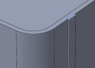
My approach was to create a sketch of the cross section of the strap(s) and a sketch for the path around the tank,

The sketch is in blue, there is a faint pink line which is the path, and it is generated by creating a transverse plane through the tank and "converting entities" where the tank and the plane intersect.
I then swept the blue sketch along the pink path, no issues.
For fun, I followed BTJames' suggestion too

create a sketch (in blue) by converting entities as above, and offsetting them. extrude that.

and finally pattern the extrusion
Hopefully this will help Thomas' project
meanwhile, in an obscure corner of the www...

 english.stackexchange.com
atb
Simon
My approach was to create a sketch of the cross section of the strap(s) and a sketch for the path around the tank,
The sketch is in blue, there is a faint pink line which is the path, and it is generated by creating a transverse plane through the tank and "converting entities" where the tank and the plane intersect.
I then swept the blue sketch along the pink path, no issues.
For fun, I followed BTJames' suggestion too
create a sketch (in blue) by converting entities as above, and offsetting them. extrude that.
and finally pattern the extrusion
Hopefully this will help Thomas' project
meanwhile, in an obscure corner of the www...
Origin of the phrase, "There's more than one way to skin a cat."
The meaning is clear, but where did this phrase originate? Was it always such a gruesome reference?
english.stackexchange.com
atb
Simon