Spike's folding table - Catching a Toad

Scale7JB

Western Thunderer
JB (@Scale7JB),

Did you get around to finding this model?

I shall be going to the S7 AGM so maybe you could pass the model to someone from the East Anglian area who is going to the event.

regards, Graham
Hi Graham,

It’s not hard to lose stuff in the flat thankfully..

Apologies for completely forgetting to bring to the Albury meet. I can stick it in post or bring to Stafford?

JB.
 
Return of the Sentinel

Spike

Western Thunderer
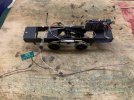
Nearly a year and a half has passed since the Sentinel featured on the folding table. In the background I have been working away on the loco. The problem area for me was working out what to do with the electrics to keep all the wiring hidden. I finally have settled on how to control all the lights which results in a lot of cables running down the inside of the chassis.

There are two micro bore tubes soldered to the chassis and about 5 wires run down each tube. There is not alot of room within the bonnet once the decoder and motor are installed. As such the keep alive will be inside the cab along with the connections for all the lighting. I have designed cab fittings to concel the items.

There are still 4 sets of LED's to be installed which will not happen till the loco has been painted.

IMG_3620.JPEG

The buffer beams were attached about a year ago but never got round to posting about the progress. Better late then never.
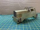
Whilst not visible in the below picture I have used MOK self contained buffers, otherwise convential buffers would have resulted in the spring being visible around the steps.

IMG_3120.jpeg

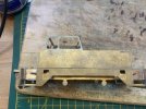
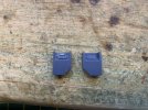
One part of the kit that I wanted to upgrade was the sandboxes. The kit calls for the plate with the two holes to be pushed back at an angle with wire forming a handle. Research showed something different, and a bit of time with CAD later and four new sandboxes with lids were produced to go behind the hole in the side once that plate had been removed.

IMG_3616.JPEG

Below is the 3D prints, the one on the left has had the wire installed to form the handle.
IMG_3618.JPEG

Final photo shows the sandbox placed behind the hole in the side, much better! Just the checker plate to be added in the half etch.

IMG_3619.JPEG

Next up is sorting the side lights and finishing the wiring.

Regards
Peter
 
A Club O Gauge Layout

Spike

Western Thunderer
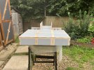
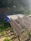
My local railway club has restarted the O guage layout about 10 years after I had built three of the seven baseboards. They have been in storage and are in really good condition. Over the past two months myself and my dad have been progressing the fourth board. Some of the parts were cut around 10 years ago and have been living in the garage waiting for their use.

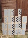
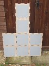
The plan for the layout was to have a split level design with the top level running along arches with a goods yard at the front. Some of the parts are
shown below, it is a giant jigsaw puzzle.

012.JPG


016.JPG
The piece above is the goods yard top and then a road tunnel that goes under the arches.

IMG_6204.JPG
IMG_6206.JPG

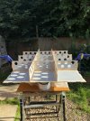
At this point the internal structure is glued in and front panel has been added. The sides are to be added next.

IMG_6208.JPG

Went a bit over the top with clamps. Once the glue is dry the parts are pinned together.

The Basingstoke Club who are building the O gauge layout are having an open day on the 3rd September where the plans for the O gauge layout will be on show and the boards built to date will be on display. We are hoping to get the other boards built by the end of October so trackwork can commence.

Regards
Peter
 
GWR AA19 Toad

Spike

Western Thunderer
Over the past year I have been working away at a Parkside kit of a GWR AA19 Brake Van.

I decided to build it pretty much as per the kit but with a couple of upgrades:
1. Replacing the plastic handbrake column and handle with a cast brass version.
2. Suspension units from Exactoscale.

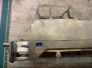
You can see the Exactoscle units below, I had to reduce the height on the internal chassis beams to accomodate the units. I have also got rid of the Parkside breakshoes and hangers and used Slaters instead. I managed to break one of the parkside yokes hence the single brass version.
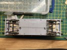
IMG_6573.JPG

The next change I made was to the Handbrake column. I think I used a CPL version instead on which you can see the teeth and latch. Overall a much better representation.
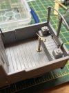
IMG_6574.JPG

I had trouble with the handrail brackets provided in the kit. I ended up ditching them and my Dad mentioned there was an article in MRJ about the brackets being made out of metal. Quick trip up to the library and volume in hand back to the shed to start creating the brackets. It took me a day to file and drill the holes in all of them, a couple of cut fingers but worth the effort as once attached to the model it really improved the appearance.
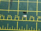
IMG_6572.JPG

First set of brackets and handrails fitted. I have corrected the wonky bit on the left hand side.
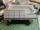

IMG_6570.JPG

Today I have been adding the footboards, the top step has been filled down in the middle to represent the guard climbing in and out of the van and wearing away the timber. I have only placed the roof on at the moment - glazing still to be added. I am leaving the extra support on the veranda end till the end.
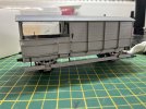
IMG_6607.JPG

Overall I am pleased with the Brake Van, I have a soft spot for Brake Vans and whilst this was not exactly the right period for me I enjoyed building it and will still find a home on the layout.

Peter
 
Last edited:

Dog Star

Western Thunderer
I had trouble with the handrail brackets provided in the kit. I ended up ditching them and my Dad mentioned there was an article in MRJ about the brackets being made out of metal. Quick trip up to the library and volume in hand back to the shed to start creating the brackets.
The article in the MRJ is by John Hayes, "Uncommon Toad" (pg.31, issue no.92, 1997). Peter's reference to the library refers to the bookshelves in our modelling room.
 
Top