The D&RGW and Rio Grande Southern in 0n3

mickoo

Western Thunderer
I find it very easy to get sidetracked and diverted from the job in hand in this hobby.

So this Accucraft 1:20.3 scale K27 appeared on UK Ebay at what I thought was a very reasonable Buy it Now price. However the details given were very brief and the photos were all taken from one side so didn't show all of the loco. According to the description it had paint damage to the cab roof and other areas, the cab roof paint damage was obvious, the "other areas" not so, but it was covered in a layer of dirt so who knows what was underneath. It was said to have been purchased new 25 years ago, test run but never run on a track and stored ever since. It had obviously been stored exposed in a shed or garage to collect so much dirt. I did get more photos from the seller taken from the other side and the information that it had a sound system of some sort.
According to the Brass Guide these electric versions were produced in 2000 and 2001, and live steam versions in 2003 and 2006.

However as the saying goes "nothing ventured nothing gained" or perhaps more appropriate "a fool and his money......", with several watchers and nearly a month to go I didn't bother with the make an offer option but bought at the Buy it Now price. Against better judgement I arranged for it to be delivered, but fortunately it was well packed and appeared to have suffered no damage in transit. The only items that appear to be missing are one of the tender re-railing ramps and the air hoses at each end. The loco and tender needed partly dismantling and two thorough washes to remove all the muck. The cab roof had traces of green oxidation as well as a small damaged area of paintwork so it was completely stripped down to bare metal and repainted with black self etch primer and satin black. The cab had to be removed to clean the muck off the firebox and backhead, so that made the roof painting a lot easier, these locos are very heavy and awkward to handle complete. Elsewhere there were traces of green oxidation on and around some of the fixing screws. These are hex headed 1.6mm or 2mm dia. brass which are chemically blackened rather than painted. So they could be removed, cleaned up, any residue on the paintwork around the screw cleaned off and the screws replaced and painted. Otherwise any other paintwork required was just touching up small areas. The number decals on the left hand cab side have partly flaked off, so replacement decals have been ordered. The wheels show no sign of wear, so it seems to have had little use or maybe only test run as the Ebay description. I've got no live rail 45mm track, but lifted off its drivers and run on 12 volts its smooth running and very quiet.

One potential problem with these models is the front pilot beam. The loco is very heavy and the only way of lifting at the front end without some special kind of lifting device is by placing your hand under the pilot. This can tend to bend the front of the sheet metal pilot beam and break the joint between the front and the top. There were signs that this joint was starting to split, so its been re-soldered at the rear and short lengths of angle added at the rear to reinforce the joint. The black paint Accucraft use will stand soldering with a blowtorch without any ill effects, you just have to watch other items don't drop off in the process. A similar loco for sale on US Ebay recently had suffered the same problem and the item description stated "The pilot attachment has been repaired, and while still attached could use a bit of attention to fully correct". The bit of attention was rather an understatement as despite the botched attempt at repair the pilot beam had come apart completely.

The sound system is by Sierra, an early Soundtraxx system I believe, and it was entirely self contained in the tender. The only electrical connection between the tender and loco being via the drawbar for live rail operation. The sound system was fed by a battery and also sprung plunger pickups on the tender wheels, chuff synchronisation being by two small magnets on the back of a tender wheel. I did start to figure out what wire went where and exactly how it worked, but in the event just ripped the lot out including the massive speaker, as the tender had to be completely dismantled to get rid of all the muck. Eventually the loco will be converted to RC/battery dead rail operation using the same sound system in the C16 I described earlier in this thread. I might retain the chuff synchronisation on the tender wheel if it works, although it won't be exact as the tender wheels are not exactly half the size of the drivers, 26" prototype tender against 40" of the driving wheels.


So overall the conclusion is :) :) :) :) :) :)
Nice when you get a bargain :thumbs:

Looks just the ticket :cool:
 

Tim Humphreys ex Mudhen

Western Thunderer
The Mudhen is a K27 2-8-2 loco that supposedly got its nickname because they waddled like a mudhen, the bird that is. The K28 as featured in the above video was often referred to as the sports model to reflect its power and ride.
With all this talk of On3 modelling I managed to buy this brass K36 a couple of days ago. Its rather smaller than my 1.20.3 version but very pretty.

all the best
Tim

DSC04557.jpg
 

simond

Western Thunderer
I understand the waddling simile, given the large reciprocating bits and narrow gauge, though it’s got a fairly long wheelbase.

Thank you all. Every day is a school day. :)
S
 

adrian

Flying Squad
The Mudhen is a K27 2-8-2 loco that supposedly got its nickname because they waddled like a mudhen, the bird that is. The K28 as featured in the above video was often referred to as the sports model to reflect its power and ride.
With all this talk of On3 modelling I managed to buy this brass K36 a couple of days ago. Its rather smaller than my 1.20.3 version but very pretty.

Thanks for the excuse to post and remind myself of Cumbres and Toltec. circa 1996.
Cumbres - 2.jpeg

I don't seem to recollect the trackbed being that precarious

Cumbres - 1.jpeg
 

Yorkshire Dave

Western Thunderer
I always wondered why North American locos always chuffed to a standstill in Cowboy movies whereas in Britain the steam was shut off and locos coasted to a stop (unless on an incline). In the USA, the driver allows the coach brakes to stop the train thereby keeping the couplings tight. The loco is pulling right to a stop. Tight couplings gives a smoother take off when setting off with no jolt to the passengers.

In the UK, screw couplings keep passenger consists 'tight'.

Wouldn't have the SR, LNER and later BR have adopted a similar practice when hauling knuckle coupled rakes albeit the loco/coach coupling was screw. Or did the corridor connection and buffing plates connections keep the rakes tight?
 

adrian

Flying Squad
. The mountain ledges look to be tied with metal rods in the vid I posted. An impressive outfit.
It may well have been in the video, it was slightly different on the Durango-Silverton line. That was a rather different and more commercial run operation to the Cumbres and Toltec line which I found more enthusiast orientated. For the Durango line when you bought your ticket you were allocated a seat in a coach and that's was it. Whereas the Cumbres line, slightly longer, you had freedom to wander through the train, no allocated seats and they had a box car and open wagon. So you were free to wander through for that open air experience as well.
Cumbres2 - 2.jpeg

Cumbres2 - 1.jpeg
 

Dave Holt

Western Thunderer
Watched the Durango video this afternoon. Wow, I had a feeling of vertigo just watching. Don't think I could go on that, having seen it! Thought the Ffestiniog had fairly steep drop on the way up to Tan-y-Bwlch but now I know different.
Dave.
 

PhilH

Western Thunderer
Trestle 001B.jpg

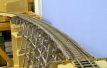
The trestle bents have now been positioned on their foundations and supporting woodwork. The foundation blocks will be painted to represent concrete before the bents are finally fixed in place.


Trestle 002B.jpg

The foundations needed some adjustment to get the top of the bents exactly to the required height. The final height adjustments involved just thin strips of paper. When the level on top (used just as a straight edge as the top of the trestle is on a gradient) is moved slightly side to side and all 8 bents move similarly in unison you know its just about right. The ground side slopes on each side are fairly steep so will probably have to incorporate some rock outcrops.


Trestle 003B.jpg

Now the supports have been set to line and level from existing track alongside, the next step is to remove the temporary bridge and push the structure into to its final position. Then the bulkheads at each end can be added and the structure tied together longitudinally ready for adding the stringers across each span.
 

PhilH

Western Thunderer
That looks fantastic! JB.

Thanks JB, but its just a pile of wood more neatly arranged ! ;)


1. Trestle 100B.jpg


2. Trestle 101B.jpg

The temporary bridge track has been removed and the trestle slid over to its final position. The timber bulkheads were fitted at each end and connected to pins in the centre of each bent with temporary brass strips to firmly align the structure prior to fitting the stringers.

3. Trestle 102B.jpg

The ends of the assembled sets of stringers were trimmed to length and the required angle on a disc sander and positioned on top of the bents with the aid of brass spacers. Probably about the lower third or half of the timber bulkheads will be buried when the scenery is added.


4. Trestle 105B.jpg

All the stringers now fixed in position ready to receive the ties. The lower longitudinal members (known as girts) have also been added.


5. Trestle 104B.jpg

Now the main structure is complete and all tied together its surprisingly rigid. The lowest row of girts below each span has been omitted at this stage to give a bit more room to complete the scenery underneath the trestle.


6. Trestle 103B.jpg

The shadow of the trestle on the window blind, which will eventually form the backscene, is rather noticeable. A problem due to squeezing too much layout in too small a space. The blind is in front of the window frame at the moment so I can gain another 4-5 inches by moving it away from the trestle and closer to the window within the frame. Some overhead lighting may also help. If that doesn't work it may require removal of the window and replacing it with a new bay window. :rolleyes:

The next job is fixing the ties to the top of the stringers.


mickoo

Western Thunderer
Nice bridge :thumbs:

For the backdrop I'd go with a near vertical cliff face, not all trestles actually cross water or anything tangible, they're often there because the landscape simply cannot support a road bed.

A couple I had in mind are these two in the Feather River Canyon

Mountain Train by Patrick Dirden, on Flickr

BNSF westbound at Rock Creek by Patrick Dirden, on Flickr

Much As I love O gauge I'm very tempted to do N in scenery like this :cool:
 

RGSrr

Member
Thanks JB, but its just a pile of wood more neatly arranged ! ;)


View attachment 151440


View attachment 151441

The temporary bridge track has been removed and the trestle slid over to its final position. The timber bulkheads were fitted at each end and connected to pins in the centre of each bent with temporary brass strips to firmly align the structure prior to fitting the stringers.


View attachment 151442

The ends of the assembled sets of stringers were trimmed to length and the required angle on a disc sander and positioned on top of the bents with the aid of brass spacers. Probably about the lower third or half of the timber bulkheads will be buried when the scenery is added.


View attachment 151443

All the stringers now fixed in position ready to receive the ties. The lower longitudinal members (known as girts) have also been added.


View attachment 151444

Now the main structure is complete and all tied together its surprisingly rigid. The lowest row of girts below each span has been omitted at this stage to give a bit more room to complete the scenery underneath the trestle.


View attachment 151445
The shadow of the trestle on the window blind, which will eventually form the backscene, is rather noticeable. A problem due to squeezing too much layout in too small a space. The blind is in front of the window frame at the moment so I can gain another 4-5 inches by moving it away from the trestle and closer to the window within the frame. Some overhead lighting may also help. If that doesn't work it may require removal of the window and replacing it with a new bay window. :rolleyes:

The next job is fixing the ties to the top of the stringers.

Hi Phil
Trestle is looks fantastic, shadows on the blind will be lost in the background once you photo enhance the blind. Perhaps a bit of gentle up lighting behind the scenery
 

PhilH

Western Thunderer
Thanks for your suggestions Simon and Mick, although there isn't much room for anything behind the trestle. I would normally have the window blind up during daytime, except when I'm operating the layout, so would prefer to obstruct the window opening as little as possible, although another point to consider is the effect of sunlight through the window on the trestle woodwork and the scenery..........Hmmm :rolleyes:, Maybe scrap the layout, move to a house with a basement and start all over again......on second thoughts - Maybe Not !


1. Trestle 016B.jpg


2. Trestle 017B.jpg

The ties were fixed to the stringers at ¼" centres (one scale foot) using a scale drawing as a template. I could have used spacers between each tie, but if they're removed before the glue sets you could risk disturbing the tie, wait until the glue sets and they may be fixed by glue oozing out from under the ties. Also being on a curve the ties are all at very slightly different angles to each other. The 4 gaps are for longer ties to carry the water barrel platforms. Throughout the build I've used Titebond wood adhesive which sets fairly quickly.


3. Trestle Plan.JPG

I positioned the bents by reference to the temporary track alongside which should have been 96" radius and I think I checked this beforehand, or did I ???? Anyway, whatever, as it turned out with the stringers in place it didn't exactly match the original plan, being a maximum of just over 3mm out in the centre of the trestle, so the above drawing has a slightly revised line incorporating four different radii and, dare I say it, a very short length of straight (although this has been eased into a slight curve when the rails were laid) to match the exact position of the stringers. This was all worked out on a CAD program and the ties positioned radially to each different radius, maybe a little over the top ?


4. Trestle 019B.jpg

With the ties positioned in accordance with the drawing it was fairly simple to lay the rails centred on the ties with suitable gauges - merely lengths of ¼" dia. brass rod with two grooves and short lengths of brass channel soldered on each end. The rails are Code 100 treated with Dyson Brass Brown. It's not 100% successful on nickel silver but it gives a reasonable appearance for now. They will be painted rust colour if ....sorry, when the remainder of the layout rail gets painted.


5. Spikes.jpg

The spikes on the visible side of the rail are Micro Engineering Micro Spikes #30-108, on the left in the above photo. These don't have much of a point so require clearance holes 0.5mm dia. and are fixed with a dab of super glue on the end before insertion. I didn't have enough of these to do all the trestle and, with apparently no available supplies in the UK, on the non viewing side I used Micro Engineering's Small Spikes #30-106 (on right in above photo) with the heads trimmed as in the centre. These can be forced in with a 0.5mm dia. pilot hole.


6. Trestle 021B.jpg

Rails in place, spiked about every fourth or fifth tie initially​


7. Trestle 022B.jpg

The change in curvature at each end of the trestle is not ideal, but required because of the space available, and the rails needed a lot of adjustment to get a smooth transition. Beyond the trestle at this end the line will pass through a rock cutting before entering the tunnel mouth


Well it seems to work OK, nothings fallen off..........yet ! :)

There's about half the spikes still to fix, and then the guard rails and guard timbers (fixed to the edge of the ties) to provide.
 
Last edited:

adrian

Flying Squad
Thanks for your suggestions Simon and Mick, although there isn't much room for anything behind the trestle. I would normally have the window blind up during daytime, except when I'm operating the layout, so would prefer to obstruct the window opening as little as possible,
A suitable photo printed on the blind might work, if the lower part is dark enough.
Not railway related but for my eldest with an interest in camper vans sorted out this window blind from a photo.
blind - 1.jpeg
 

PhilH

Western Thunderer
A suitable photo printed on the blind might work, if the lower part is dark enough.
Not railway related but for my eldest with an interest in camper vans sorted out this window blind from a photo.

Yes Adrian, I had something like that in mind, its just a case of finding a suitable photo or maybe combination of photos. There seems to be several firms supplying custom made blinds and as a matter of interest, which company did you use and were you happy with the results, it certainly looks pretty good from the photo (if you like camper vans !).
 

Big Train James

Western Thunderer
You might take a look at Backdropwarehouse.com. The vendor features large format photo backdrops, and I know that he has quite a few in and around the narrow gauge areas of Colorado. I would look at the "Rugged Mountains" tab and the "Mountains with Hills" tab for starters. I have no idea if any of the offered options would be suitable, or if you could even arrange with the vendor for media in the necessary format to make the blind. But it might be worth a punt.

I'm trying to remember if there was another vendor that also featured photo backdrops for the area. One fellow modeler here is doing the Cumbres & Toltec in HOn3, and we went looking for photo backdrops depicting Chama and surrounding areas. I'll have to dig around and see what I can find, there might be a second vendor that may offer something worthwhile.
 

PhilH

Western Thunderer
Trestle 017B.jpg

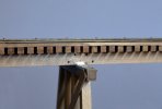
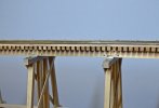
The guard rails and guard timbers on the edge of the ties have now been added to the trestle deck. The guard rails on the prototype seem to be normally lighter section than the running rails, probably rail replaced when the running rails were relaid with heavier section rail, but I had spare code 100 so...... also I think they should be just a touch further away from the running rails :(. The guard rails are spiked to every third tie and have only two bolt fishplates. The dark brown colour of the rails is temporary and they will be painted a lighter red/brown rust colour later. I've omitted the water barrel platforms, not all trestles of this length had them, if I provided them the length would probably only justify one in the middle, if it was on the viewing side it would obstruct the view of the train, if it was on the other side it would produce an awkward shadow on the backscene, and its a damn sight easier to leave them out ! :rolleyes:

Trestle 018B.jpg

The guard timbers are joined with half-lap joints and fixed with a bolt through the tie. The 3 fixings between the joints are coach screws so don't need nuts/washers under the ties. The guard timbers should really be notched for every tie, that would be about 288 notches to cut and with slightly different spacing on each side of the trestle because of the curve, so I thought I'd pass on that one.


Trestle 019B.jpg

The galvanised steel sheets for fire protection on the top of each bent are formed from an old Elastoplast tin - remember those ? useful as tins for storage and also as a source of thin steel sheet. The exposed surface is the painted outside of the tin with the paint removed, not the plated inside, so at the moment its polished steel. I'm not sure whether they need painting or just dulling down to look more like weathered galvanised steel.


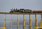
Trestle 020B.jpg

From this angle the room lighting makes the timber appear yellow :oops:


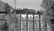
Trestle 022 OP-8104 © Denver Public Library.jpg

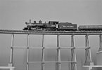
D&RGW #464 on the RGS - Otto Perry photo © Denver Public Library


Trestle 021B.jpg

Next the scenery, backscene and maybe lots of trees ? (can't do #464 at present !)

 
Top