Tom Mallard’s Workbench L&B in 7mm scale and clockwork CR 828, 4mm Saints

Tom Mallard

Western Thunderer
YEO EXE hornblocks in 2.JPGTAW pony trucks 1.JPG

Thankyou Neil.

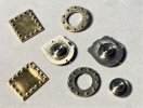
What a palaver. The hornblocks are finally in, but not without some work to machine appropriate axleboxes from ColPhos phosphor bronze. This is likely overkill, but in terms of machining is much more amenable material than the usual pinkish stuff that is the opposite.

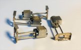
The hornguides are a casting directly from a 3D printed wax, as using an adapted casting as a pattern for subsequent casting introduced a deformed casting which I wasn't keen on working with in what is always a fraught exercise in any case. The plan in the end is have sprung suspension, using Exactoscale hollow grub screws through the hole in the top and little coil springs set into the axleboxes. I hope the springs I get are going to be stiff enough.

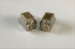
Taw's bogies (as they are called by Manning Wardle) follow the shape of the prototype with cast front, rear and axle keeps. The axleboxes (not shown) have been machined from Paxolin for insulation purposes and utilise a Phosphor bronze insert for the bearing.

I noted with significant interest the announcement from Lionheart!

Best regards

Tom
 
Last edited:

Tom Mallard

Western Thunderer
IMG_0784.JPGIMG_0957.JPG IMG_0941.JPGIMG_0914.JPG

Some progress again and quite a milestone from my point of view.

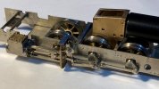
I learned how to make wheelsets from scratch, and they've come out well. Front and rear of each wheel is reproduced to scale. Although the stainless tyres are epoxied to the centres, on the driving wheels I have ensured electrical isolation with a Paxolin bush at the hub and on the pony truck wheels used a split axle with insulated axleboxes. The axles are shouldered for the correct flycrank appearance and location, and are a little proud just like the prototype.

Slaters SG38 gearboxes have been used, the models having been designed for these from the start and these come with the newly available Faulhaber motor option though I would have prefered not to have a double ended motor, but Slaters reasoned that modellers like to fit flywheels. Some clearance issues were found to the rear of the gearbox and I will likely remove more material to avoid impingment.

I've sourced a lot of small springs to suspend the model, assuming a completed weight around 500g. Time will tell if this is the right value to work around.

Next I should probably make the crankpins and cylinders and then with some rods on it will really look like a Manning Wardle.

Best regards

Tom
 
Last edited:

AdeMoore

Western Thunderer
Mind blowing skill Tom, to produce the quality I see above.
Hats off to you Sir. Fantastic to see, looking forward to more.
Your mention of the Lionheart offering was not lost on me, I doubt the underpinnings are a patch on your build!
Cheers.
 

michael mott

Western Thunderer
View attachment 146212
It is difficult to convey the time it takes to make valvegear properly, but from the last post to this, it's more or less been the main task. All the valvegear is machined in two planes to reproduce as much of the relief as possible. None of it is finished yet - theres lots of finishing of the surfaces to come. The naming of all the parts is most peculiar compared to Walschaerts' type, yet the parts occupy more or less the same location.

The connecting rods are being kept mounted on their workplates as there's still some final work to do. With the coupling rods, they will need their oil pot tops adding.

The domes have crept in again, as I've added the rolled edge to these three, and some partially machined wheel castings have been included too.

I am unsure (what a surprise!) whether to use free machining stainless steel, or nickel silver for the tyres. Answers on the proverbial if you have any insights.

If I remember, I'll refer back to this post when there's a rolling chassis and we can see where everything went.

Best regards

Tom
Beautiful machine work on these parts, The lip on the dome is inspirational! I really do enjoy seeing skilled hand filing and finishing. What material is the valve gear made from?

Michael
 

Tom Mallard

Western Thunderer
Beautiful machine work on these parts, The lip on the dome is inspirational! I really do enjoy seeing skilled hand filing and finishing. What material is the valve gear made from?

Michael
Thanks Michael, and thanks for the question.

The valve gear is all from nickel silver, either grade NS101 bar or NS103 sheet, supplied by Metalsmith Leeds Ltd. They've supplied a lot of the materials that haven't come from the etching company, and have been great to deal with.

Hope this helps

Tom
 

Tom Mallard

Western Thunderer
MW cylinder sub assemblies.JPG
IMG_1052.JPGIMG_E1185.JPG

This is where I'm at - 3 sets of cylinders with hundreds of cosmetic studs and nuts modeled and attached, currently at 48 per side with more to add. Most of them are 0.7mm across flats. There's only one casting per side which is the motion bracket though this has a couple of nickel sheet parts added for reference face flanges where it is attached to the frame and tank on the prototype. The viewer will need to be inquisitive to see much of this when the models are complete.

I made the front and rear rings common, but with a countersunk turned central part for the front and the piston rod gland built up from profile machined parts at the rear.

The details are essentially overlays of varying thicknesses added to a sheet sub frame - the wrapper is 6 thou with the boltheads from 0.3mm wire as I drew the line at making 0.3mm hex heads.

The slidebars are sawn and machined to size from plate and include the differing top and bottom profiles. A little spacer jig for the slidebars made light work of attaching these at the correct spacing and alignment.

Enjoy your modelling.

Tom
 

Tom Mallard

Western Thunderer
IMG_1310.JPGIMG_1330.JPG

Thankyou once again for the feedback and comments, it's appreciated.

I've taken a break from the wearing process of Joy valvegear in narrow gauge applications (though that's still going well) and put some work into something more tangible.

YEO and EXE have their tank top details started, thought the sandboxes are yet to be permanently attached. The straps are detailed with more of those little machined bolt head details and the stud and nut fixings for the sand boxes are also reproduced. The filler lids are a profile machined part with the top lip machined in at this stage for a nice uniform offset.

I've recently submitted more patterns of all sorts of parts for 3D printing in wax and me being me, I've approached someone new to do this!

Tom
 

Tom Mallard

Western Thunderer
MW YEO valvegear 1.jpgMW YEO valvegear 2.jpg

This is an illustration of some of my most recent work making the parts necessary to install valvegear and motion parts on the Manning Wardles. Even more steps into the darkness.

The separate fly cranks had added more sources of error to the mechanism and some relieving of the coupling rod holes was necessary. I take the probably highly frowned upon route of broaching out the holes by only the smallest amount until proper movement is attained rather than jumping up 1/10mm at a time which is often far too much in one go.

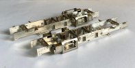
Crankpins (free machining phosphor bronze) and their nuts (nickel silver screws tapped 12BA) are handmade to suit the requirements of the model, and pins turned to fit each valvegear pivot while representiing the appropriate head appearance. Tiny die blocks are fitted into the radius link grooves for proper function of the radius rod since I have no previous experience of Joy valvegear I wasn't happy taking short cuts here. The brackets that support the radius link are little castings which locate in holes on the motion bracket. It is a relief that the part of the reversing shaft protruding from the radius link located perfectly in its slot.

Although it sounds simple, assembly is not straightforward as separation points are limited to the connecting rod and return crank leaving a lot of careful manipulation of this subassembly.

Still the valve rod, guide and spindle to add, then the sheeting over the motion bracket and slidebars to partially obscure it all!

Enjoy your modelling.

Tom
 

Tim Watson

Western Thunderer
Lovely to see that Joy valve gear coming together, Tom. I really ought to get back to my 4mm scale version, but the L&B project is very backstage at the moment.

Tim
 
Last edited:

Tom Mallard

Western Thunderer
Thanks everyone.
Lovely to see that Joy valve gear combing together, Tom. I really ought to get back to my 4mm scale version, but the L&B project is very backstage at the moment.

Tim
It is nice to finally see it in place and quite a relief after so long in preparation, Tim. I think we are all waiting to see your 4mm scale version but obviously your 2mm scale work must take precedence and the fun of your 'King Arthur'.

Tom
 

Tom Mallard

Western Thunderer
MW YEO EXE chassis with cylinders and brakes 2.JPGMW YEO with cyclinders and brakes 4.jpg

Hello again, folks. Progress is more positive this time now that behind the scenes effort has been assembled as completed motion assemblies for each engine, the motion covers and piston guides added and the brakegear installed. The vacuum cylinders and handbrake linkage should be added next. I wish solder wasn't such a yucky grey, but at least we know the parts won't fall off...

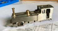
The second image shows YEO with bodywork sat on chassis showing how the iconic appearance of the L&B Manning Wardles is starting to appear!

Best regards

Tom
 
Top