Tom Mallard’s Workbench L&B in 7mm scale and clockwork CR 828, 4mm Saints

Tom Mallard

Western Thunderer
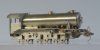
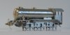
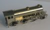
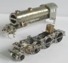
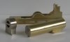
Things are looking up for the K3 as decorating the model has started in ernest.

The door is yet to be attached so might need tweeking, same for the blower pipe on the lhs with its out of position pipe clips. Overall it's coming along nicely and becoming enjoyable to work on at last.

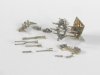
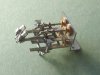
Some of the details were unusually finicky, such as the position of the smokebox door handrail, those curious door stop extensions to the hinge straps and the upper lamp iron. These didn't appear on the GA so were built up and checked against photographic evidence in conjunction with the odd pearl from the RCTS book.

I used a Dave Bradwell vacuum pipe casting as it best represented the type fitted to the engine, thought the carriage warming pipe is one of my own. The photos show that these were not often fitted to the front of this class.

Please ask questions if you'd like to know anything in particular about the model.

Best regards

Tom
 

Attachments

  • K3 bodywork 13.jpg
    K3 bodywork 13.jpg
    188.3 KB · Views: 337
  • K3 bodywork 12.jpg
    K3 bodywork 12.jpg
    159.8 KB · Views: 338

Tom Mallard

Western Thunderer
As is usual, my model has gone through a metamorphosis from wheel-less frames and body to mostly finished.

The bodywork has it's lubricator and anticarbonsiation pipework in place, and footsteps for the crew.

The frames had all the motion and slidebars checked very thoroughly. Really it is a matter of making sure things slide or rotate in a plane as an aid to smooth running and although I had tried to make my life straight forward there are always a couple of snags to iron out. For example the crossheads require careful finishing to slide in alignment with their piston rods and castings don't always come out as square or dimensionally stable as the pattern they are made from. My expansion link is pinned to the motion bracket with shouldered sub axles which I think is a little bit less prone to causing trouble further down the line.

The return cranks are attached to Exactoscale top hats which locate into a sleeve of predetermined length which in turn locates on an opposing top hat bearing and when tightened up will set the return cranks securely. This work was done before the wheelsets were finally assembled. As a refinement over previous models, I supplied my caster with a pattern for the return crank bearing cover. This looks a lot nicer than an etched cover.

The wheelsets are the specially made Exactoscale K3 type with everything exactly right and the gears are by High Level and held in profile milled side plates. Clearances caused a headache as there is a boss on the face of the driving wheels which coupled with the base of the top-hat crankpin bearings added a minimum of 0.5mm to the width over faces of the coupling rods and crankpin nuts - not something we need in P4. Consequently a slow and methodical game of checking and amending clearances ensued until the coupled wheels could reliably rotate without the lead crankpin nuts clouting the back of the slidebars.

Still to add are various chassis parts: reversing links, pickups and drawbar are the main ones. The body needs a small number of parts adding and then some paint!

Best regards

Tom
 

Attachments

  • K3 completion 1a.jpg
    K3 completion 1a.jpg
    126.5 KB · Views: 308
  • K3 body and chassis 1.jpg
    K3 body and chassis 1.jpg
    105.1 KB · Views: 311
  • K3 chassis 1.jpg
    K3 chassis 1.jpg
    117.3 KB · Views: 313

Len Cattley

Western Thunderer
Hi Tim, [/QUOTE]"The return cranks are attached to Exactoscale top hats which locate into a sleeve of predetermined length which in turn locates on an opposing top hat bearing and when tightened up will set the return cranks securely. This work was done before the wheelsets were finally assembled. As a refinement over previous models, I supplied my caster with a pattern for the return crank bearing cover. This looks a lot nicer than an etched cover.[/QUOTE]
Where can you get this casting.
Len
 

Tom Mallard

Western Thunderer
"The return cranks are attached to Exactoscale top hats which locate into a sleeve of predetermined length which in turn locates on an opposing top hat bearing and when tightened up will set the return cranks securely. This work was done before the wheelsets were finally assembled. As a refinement over previous models, I supplied my caster with a pattern for the return crank bearing cover. This looks a lot nicer than an etched cover.[/QUOTE]
Where can you get this casting.
Len[/QUOTE]
Hi Len,

similar to the etchings I use, for the time being these fall into the category of non-commercial items which I use for my own purposes. It is a shame I know, but I only get them done in very limited quantities specially for my own work.

Best regards

Tom
 

45609

Member
As a refinement over previous models, I supplied my caster with a pattern for the return crank bearing cover. This looks a lot nicer than an etched cover.

Hi Tim, Where can you get this casting?
Len

Len,

Hopefully a more helpful reply.....From Dave Bradwell

http://traders.scalefour.org/DaveBradwell/castings/

Mould 8. – £5.50
Comprises: Flatter smokebox door, PV front heads, PV rear heads with valve guides, ecc rod brg. cover.

Mould 21. – £5.50
(2 reqd). 4 spring dampers, PV heads front and rear, sandpipe, crosshead nose, ecc rod brg cover, piston gland.

Mould 28. – £6.00 Pr
Rear piston valve heads, front valve head, 2 glands, 2 ecc rod brg covers, AWS battery box.

He is willing to sell stuff because he has a different business model by funding the development costs for castings and etchings out of his own pocket. Mould 28 would be the most cost effective solution as you get 2 per sprue.

Morgan
 

Tom Mallard

Western Thunderer
Finally some of the K3 is off to get some paint! I asked Ian Rathbone to paint and line the K3 as he is unmatched in 4mm scale (and 7mm too...).

I haven't left many details off the outside of the bodywork, but all of the cab interior unscrews to make those parts easier to paint and detail. The tender body will be going with it, but we've seen that before.

Just for posterity I have photographed the loco before the paint is applied.

Best regards

Tom
 

Attachments

  • K3 bodywork 15.JPG
    K3 bodywork 15.JPG
    136.1 KB · Views: 264

Tom Mallard

Western Thunderer
Not sure I would paint that, it is stunning. Thank you for sharing it
Thanks Puddlejumper and others for the kind remarks.

Paint is a necessary evil I'm afraid - our model railways would look peculiar if our trains were all shiney metal amongst the scenery. Saying that, it is commonplace on a lot of model railways as things start to form an orderly finishing queue...

But the photo keeps it paintless for posterity!

Best regards

Tom
 

Tom Mallard

Western Thunderer
A bit of 'light relief' or so I hope. A LSWR D15 in as built condition. This is from etches specially designed by Martin Finney and it makes a very pleasant change to the last 12 months of self imposed designing and scratchbuilding.

Eventually I found the camera (remembered to take a picture) though with a proviso that pictures will appear slightly late.

This is the tank for the 4500 gallon tender fitted to the D15's and had a piggy-back tank extension and extra two extra coal rails compared to the usual 4000 gallon water cart type.

Best regards

Tom
 

Attachments

  • tender tank 2 D15.jpg
    tender tank 2 D15.jpg
    70.6 KB · Views: 203

Steph Dale

Western Thunderer
There's some 'fun' you're going to have with this one! A few years ago I did see a version Martin was building in P4 from etches he'd produced; it looked stunning.

It's still a complex and sometimes confusing prototype...

Steph
 

Tom Mallard

Western Thunderer
There's some 'fun' you're going to have with this one! A few years ago I did see a version Martin was building in P4 from etches he'd produced; it looked stunning.

It's still a complex and sometimes confusing prototype...

Steph
The main fun to be had on the D15 is defininitely the inside Walschaerts valvegear. Fortunately most of this is provided for in the kit (apart from machining some valve spindles) and there are some cunning assembly solutions to make sure that it can be put together at the appropriate time. The supplied drawings and a bit of careful assembly will all lead to the right outcome...
 

Tom Mallard

Western Thunderer
The D15 moves towards some more interesting assemblies as the frames come together. All except the turnings on the back of the cylinder chest is provided for with the etchings, but a lot of careful assembly is required along with the usual removal of cusps on the cosmetic faces. Many parts of the valvegear are yet to be made, but at least now there is something to hang them off. For practicality, the critical part for all of it is that it can be assembled/disassembled as required and to this end several screwed valvegear pivots are incorporated into the design. The screws are to be 16BA with small sections of turned and faced tube to act as bearings at the relevant points.

The bodywork has the valences folded up and the splasher sides installed on the footplate, but await the frames and cab front/splasher tops.

The tender has its valences, frames and bogies assembled to go with the tank, but I thought I ought to progress to the engine so that once the wheelsets are together and the crankaxle made I can set up the relative levels between engine and tender properly.

Best regards

Tom
 

Attachments

  • D15 frames motion bracket and bogie.JPG
    D15 frames motion bracket and bogie.JPG
    82 KB · Views: 188

Tom Mallard

Western Thunderer
A bit more interesting this time, with some work done on Drummond's Walscharts valvegear solution and the key subassemblies of the bodywork put together. The valvegear follows on from practise established for modelling external Walshaerts and is largely bult up from laminations held in position by drilling through the part into a block of Tufnol, threading on the components for soldering, and then carefully finished with files, emery paper and so-on to remove cusps and clean up the faces of the finished parts.

I turned a new ring from brass for the back of the smokebox/boiler interface as I felt it was a bit easier to work with than a nickel silver etching, and I could leave a little step on it to plug into the end of the boiler. Overall the footplate, boiler and smokebox are an exercise in taking time to form things as closely as possible to the desired shape before soldering into position. I am not a fan of leaning on bits of metal to keep them in position whilst the solder solidifies - who knows what else might get out of alignment or misshapen?

Hopefully not too much head scratching will be needed to pin the rest of the valvegear together, though Martin has just pointed out an interesting point re. fitting the valve spindles. I will have to remove the turnings on the front of the valve chest to thread the spindles on and then reattach!

Best regards

Tom
 

Attachments

  • D15 body components 1.JPG
    D15 body components 1.JPG
    109.1 KB · Views: 142
  • D15 motion components.JPG
    D15 motion components.JPG
    103.4 KB · Views: 148
Last edited:

Tom Mallard

Western Thunderer
Various other assemblies are complete, but in my view the most interesting is the main inside motion arrangment.

The valve spindles are necessarily from a two part turning - split where the rod meets the main spindle body - with the oiling pot machined from an oversize portion along the spindle. The valve chest covers were removed to locate the tails of the spindles then reinstated before adding the rod to keep everything in place.

To enable the whole thing to be assembled, 16BA shouldered screws hold the eccentric rod to the expansion link and the union link to the crosshead arm.

Best regards

Tom
 

Attachments

  • D15 motion components 2.jpg
    D15 motion components 2.jpg
    53.8 KB · Views: 133

45609

Member
Tom,
It would be nice to see another photo of that assembly. Whilst I think I understand your description a well lit and better focussed photo would show off the handiwork.
Cheers....Morgan
 

Tom Mallard

Western Thunderer
Tom,
It would be nice to see another photo of that assembly. Whilst I think I understand your description a well lit and better focussed photo would show off the handiwork.
Cheers....Morgan
It's funny you should mention that, Morgan, but I thought the same thing! I spoke with Heather at Guildex who is clearly very good at photography and she explained plenty of what to do. Only a small portion could be blamed on my shabby camera... I have now installed this subassembly in the frames it is looking pretty good. I'll just set the bogie up and then try photographing it in such a way that meets with more approval.

Will you be at Scaleforum?

Best regards
 
Top