You are using an out of date browser. It may not display this or other websites correctly.
You should upgrade or use an alternative browser.
You should upgrade or use an alternative browser.
4mm Brassmasters Rebuilt Royal Scot, 46109
- Thread starter Dave Holt
- Start date
P A D
Western Thunderer
After going thought the 1st two pages of this build, I can only agree with Tony.Can you stop it Dave, you are putting 7mm boys to shame! An impressive build.....
Regards
Tony
Outstanding work Dave!
P A D
Western Thunderer
Hi Dave,
What a fantastic piece of work! Inside Walshearts valve gear in 4mm is insane and the level of detail is exceptional. Is it painted yet? That's a nice Ivatt class 2 in the station. I'd like to build another to go with the one I built for my brother some years ago from the Oakville kit, but as the only available kit by DJH is the wrong side of 450 quid, I'm keeping my wallet in my pocket. For now.
Nice to see the images of Delph. I used to pass that way on business visiting a sheepskin tannery back in the 80s and the station building was still there. I wonder if it's still standing or been "developed ". The tannery buildings in Hyde have long since been converted to apartments.
Cheers,
Peter
Dave Holt
Western Thunderer
Thanks for your kind comments, Peter.
The Scot is still unpainted. I really don't relish dismantling fully completed models - it seems so much a backward step, even though it's essential to the finished loco. I consoled myself that not having any suitable red paint for between the frames was a good excuse to delay matters. Now it's other projects.
The painted class 2 tank loco is a BR Standard version rather than an Ivatt, which i also have under construction.
The station building at Delph is still there, but a housing estate has been built over the whole of the goods yard area, including the coal drops. Luckily, when i started the project, the goods shed was still complete together with some of the coal drop support pillars, so I was able to take some (film) photos.
Dave.
P A D
Western Thunderer
Hi Dave,
I should have looked closer at the class 2, as at a glance the Ivatt and BR versions are very similar.
Red on the inside of the frames! Your insanity knows no bounds. Yeah, it's heart breaking dismantling a finished loco after all the time spent building it.
Shame about the goods yard. I think it was still there when I used to drive by. Is my memory playing tricks or was there a carriage parked in the station back in the 80s?
Cheers,
Peter
Dave Holt
Western Thunderer
Peter,
Your memory is not playing tricks regarding a carriage at Delph. A BR Mk1, in faded maroon, and a couple of goods wagons were there when I took my site photos.
According to Larry Goddard's book on the Delph, back in the 1970s, there were two different industrial tank locos there, too.
Dave.
Your memory is not playing tricks regarding a carriage at Delph. A BR Mk1, in faded maroon, and a couple of goods wagons were there when I took my site photos.
According to Larry Goddard's book on the Delph, back in the 1970s, there were two different industrial tank locos there, too.
Dave.
Darren Gaffney
Member
Dave,
I’m hoping you can help. I have finally plucked up the courage to start my Brassmasters Rebuilt Royal Scot. Tender is complete, and rolling chassis almost so. I’ve hit a roadblock though with the bogie. No issue with the lateral springing (your earlier posts and pictures helped), but I can’t figure out the “plunger” approach described in the instructions. I’m not sure if I’m missing the “plungers” from the kit, or if I’m just missing the obvious. You constructed a bespoke set up for your equalising beams, whereas I’d be happy with that described in the instructions if I could just figure it out.
Do you happen to have any helpful pictures because “plungers” aren’t even listed on the parts listing.
Thanks in advance
Darren
Dave Holt
Western Thunderer
Darren,
The Brassmasters bogie suspension plungers are small steel panel pins with a 1 mm diameter shaft, if I recall. I recently made some replacements for a friends Jubilee where they were lost. I used some lengths of 1 mm rod with a short length of tube soldered at one end - actually, there may have been two layers of telescopic tubes to give an O/D matching or slightly larger than the short springs provided for the bogie suspension. These fit into clearance holes drilled vertically through the centre of the compensating beams - a bit of a laborious job unless you have a small vertical drill.
Hope that points you in the right direction.
Dave.
Darren Gaffney
Member
Dave
Many thanks for the pointers - the two 1mm panel pins and associated springs are indeed present. I’ve bored the top of the equalising beams but I’m awaiting bogie wheels from Alan Gibson for a dry fit to see how deep I have to bore the 1.15mm holes to provide the required vertical clearance (if the plungers/pins are cut to 8mm length as instructed)
Made a start on cylinder stretcher and motion bracket. Brass origami as you mentioned. I haven’t put the bend in yet as I need to get to my bending bars and they’re at home (I work away during the week).
Progress will slow as travelling abroad next week.
Dave Holt
Western Thunderer
Darren.
Good luck with bending up the valve gear frame. The lower slide bar supports are pretty easy to snap off, as I found out.
Regarding the bogie springs and plungers, I'd be surprised if you have to counter bore the 1.1 mm dia. holes. Fitting 14 BA washers under the springs to get an adequate load on the bogie is more likely.
Dave.
Ian@StEnochs
Western Thunderer
On my 7mm Scot, JLTRT kit, I used sprung plungers one either side of the bogie pivot but inclined towards the centre bearing on a slight inclined plane on the top of the bogie centre. As well as loading the bogie it keeps it on line and helps guide the loco into curves. My loco is quite heavy so the method may be a wee bit too over the top for lighter 4mm scale models.
Ian.
Ian.
Darren Gaffney
Member
Dave,
Yep the springs are quite short alright - washers will likely be a must.
I had intended completing the brake gear once the wheels were fitted to check for a free-rolling chassis with coupling rods (I'm actually delighted with this one - it was perfect at first attempt, and I like the horn-block detail and arrangement) but the clearance is so tight fitting the wheels I'll leave the brake hangers loose until I refit the wheels for the final time (post completing and painting the chassis).
In hindsight I should have made all of the brake rigging removable - I was looking at how Ian Rathbone did it on his Black 5 with tube sleeves. That's one for the next model - I have 4 other Brassmasters kits sitting under the bench.

Darren Gaffney
Member
Exactly like that - very very tidy by the way David, I'm envious!
Darren Gaffney
Member
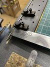
Figured out an approach for forming the round in the motion bracket - used my Metalsmith drilling table, and it worked out well. Quite an awkward piece. Haven’t offered it up for a fit yet as the model is in my weekday work home, but fingers crossed .
Alan Gibson bogie wheels delivered too, so will fit the bogie to the chassis imminently too.
Alan Gibson bogie wheels delivered too, so will fit the bogie to the chassis imminently too.
Attachments
Darren Gaffney
Member
Dave,
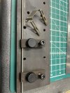
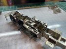
If you click on the photos they should enlarge and sharpen up - apologies, I’m doing this from my phone.
Motion bracket now dry fitted to chassis (along with cylinder stretchers). Two issues present themselves, both with the rear cross member of the motion bracket.
1) The rear cross member is about 2mm too wide.
2) The rear cross member sits about 1mm too far back in the chassis if fitted to the motion bracket as is ( and misses the slot in the chassis) i.e. the sides of the motion bracket are too long
Before I shorten the sides and rear cross member I just wanted to sanity check that I have everything right, and that you had the same issue?
I have the rear cross member sitting upside down in the picture below to try and demonstrate my issues
Attachments
Dave Holt
Western Thunderer
Darren.
It's quite a while since I built that part of my Scot. However, I don't recall having a problem with the length of the valvegear frame compared with the slots in the frames. The position and radius of the bends at the front are quite critical and, looking at mine, I think my bend starts right against the slide-bar support and is a slightly larger radius than yours.

By the nature of the Brassmasters design, the length and width of the frame and the bend radius are closely related and you need to make the valvegear frame width to be a very close fit inside the valences on the footplate. I made up the footplate before forming the frame to ensure the correct width/length relationship.
Regarding the depth of the rear cross member, I can't remember if the depth was an issue but if so, it's quite easily rectified by filing the underside of the cross member till it sits at the right height.
Dave.
It's quite a while since I built that part of my Scot. However, I don't recall having a problem with the length of the valvegear frame compared with the slots in the frames. The position and radius of the bends at the front are quite critical and, looking at mine, I think my bend starts right against the slide-bar support and is a slightly larger radius than yours.
By the nature of the Brassmasters design, the length and width of the frame and the bend radius are closely related and you need to make the valvegear frame width to be a very close fit inside the valences on the footplate. I made up the footplate before forming the frame to ensure the correct width/length relationship.
Regarding the depth of the rear cross member, I can't remember if the depth was an issue but if so, it's quite easily rectified by filing the underside of the cross member till it sits at the right height.
Dave.
Darren Gaffney
Member
As I mulled over this one today I too came to the same conclusion - I have created the error by virtue of the bend I introduced. Either the radius and/or the start point of the bend are incorrect. Some further thought required now as to whether or not I can reform the bends to correct this (difficult), or adjust the rest of the motion bracket frame to compensate for what I already have (risky as I may compound the error for further parts of the build).
Dave Holt
Western Thunderer
The valve gear frame needs to be as wide as possible within the footplate valences. You might also see from my photo that I cut off the inner parts of the frames and re-fitted them further out. I found this necessary to prevent the coupling and connecting rods fouling the inner expansion link mounting. Even then, I think I had to dress a bit off the inner support. I knew this would be a problem from a previous Scot chassis I had tried to get working for a friend, which suffered that problem. As supplied, the Brassmasters valvegear frame is not to scale dimensions regarding the inner support. I thoroughly recommend the Wild Swan Scot profile book, with it's reproduction of original LMS drawings.
Dave.
Dave.