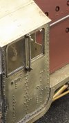
7mm David Andrews Princess - 6206 Princess Marie Louise

Rob Pulham

Western Thunderer
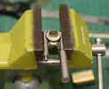
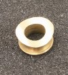
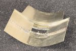
Well, what an absolute beggar making those turned out to be.

I have made at least eight or more of these plates before getting the bolt heads in the right place and mounted to the sleeve correctly. Quite embarrassingly, it was for the most part due to my failure to add up correctly when working out the degrees of spacing around the circumference...

Still I got there in the end.

53551417868_3deddce180_h.jpg

53550357107_f4b9f57e83_h.jpg
 

OzzyO

Western Thunderer
Hello Rob,

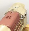
when are you going to sort out the gap between the chimney and the smokebox?

Coat on and the door closed very quietly behind me!

OzzyO.
 

Rob Pulham

Western Thunderer
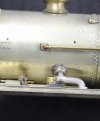
The last few sessions at the bench have been spent working on fitting the Silvertown lubricators which I made earlier in the build. After some thought I decided to drill and tap the bases/footplate rather than trying to solder them on.
I did this for two reasons

1. They would be removable for painting
2. Being solid brass, soldering them would require quite a bit of heat, potentially disturbing some of the other details fitted previously.

53562672866_98c51987b4_h.jpg

53562864183_be3f9ca0f3_h.jpg

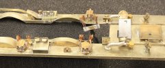
I have soldered all the wire tails to a strip of etch to keep them tidy but I may have to revisit the length and position of them once I refit the chassis.

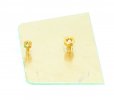
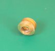
I also noted a couple of etched holes in what looks like an inspection panel on the top of the footplate so I turned a couple of small knobs to fill the holes I am not sure how prototypical this is as I couldn't find any photos which showed the inspection panels.

53562696821_4872005109.jpg
 

OzzyO

Western Thunderer
Hello Rob,

nice pipe work. What I remember about working on a black 5 was that some plates (the small ones) just had holes in them. The larger ones had a flat loop handle (like a staple) that dropped down to just about flush to the running plate.

HTH a bit

ATB

OzzyO.
 
Last edited:

Rob Pulham

Western Thunderer
I finally took the plunge and fixed the firebox to the footplate

In order to do so, I needed to attach the firebox in two planes, to the footplate and to the cab front. I was sure that If I attempted to use adhesive for both it would be a recipe for disaster. In so much as I would end up with epoxy smeared where I didn't want it on either the cab front or the footplate.

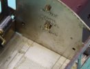
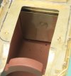
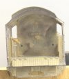
To overcome this, I made up a plate that fits inside the firebox with two studs in it (1x 10ba and 1x 8ba). They pass through the cab front and are secured by nuts within the cab. They are hidden by the back head when it's in place.

53608424990_f6373c6484_b.jpg

53608424935_3a43d924e2_h.jpg

53608174503_e29c8ee9ea_h.jpg

Knowing that I could stand the footplate on blocks of wood cab side down and put epoxy on the bottom faces of the firebox print while being able to slide into final position on the cab front made it so much easier. Finally two 12ba screws held the firebox to the footplate while it set. The plan was to remove them and replace them with studs that will screw into the holes and then hold the two lower firebox pieces into place until the epoxy sets on those. Leaving the studs in place will give a degree of mechanical strength to the glued joints too.

You can see these studs in the photo above as I took the photos after I had fitted the firebox.
 

Rob Pulham

Western Thunderer
After the fitting the firebox and checking the fit of the lower firebox sides with the chassis in place I was wondering how to hold them in position while the epoxy set.

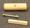
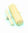
After trying and discarding a number of different clamps that I have in the workshop ranging from a small engineers clamp to a pair of 1" G clamps I decided to make a custom clamp to do the job. On my bench I just happened to have a short length of 14mm dowel which would do perfectly for what I had in mind. The bottoms of the lower firebox sides slope so I reasoned that dowel being round would allow clamping along those slopes.

Next I cut a short piece of 5mm square boxwood to a length that would sit on the footplate inside the firebox and drilled a hole through the middle. I had planned to use a 1" 10ba screw as I have quite a stock of them. Sadly it wasn't anywhere near long enough so I decided to turn myself a custom screw and to make it a bit easier to handle a longer length in the lathe, I decided to make it 8ba rather than 10 ba. I started with some 3mm brass rod and turning around 10mm at a time to minimise deflection I kept easing a bit more from the collet until I had a 30mm length that could be threaded 8 ba.

As I started to run the die down it I realised that I didn't actually need to thread the whole length so I just did about 12mm. As it turned out that wasn't quite long enough either but rather than start again I worked out that I could just counterbore the dowel to allow for enough thread to tighten the clamp. I created the counterbore with a 6mm 4 flute end mill which allowed enough clearance to use an 8ba nut spinner and for me to add a washer. As it was only to hold the parts in place there was never any need for it to be anything more than gently tightened.

53610010453_4a90cea4cd_h.jpg

53608427390_1dae32d249_h.jpg

53610010543_d47641dcf1_h.jpg

There is a hole in the upper surface of the lower firebox sides which locates over the studs mentioned in the previous post. The clamp then holds down the rear and to be belt and braces I also placed a reel of solder on the on the flat section at the front to be sure that it sat down flush on the studs and stayed there.
 

Rob Pulham

Western Thunderer
Most people reading my threads regularly, will have gathered by now that I am a bit of a tool junkie and that I don't do well with the smaller imperial measurements.

Late last year I came across a Chesterman Height Gauge which measures in both imperial and metric, at a price that I didn't need to sell a kidney to afford. It came in its original box with all the attachments including a holder for a dial test indicator. When I was looking for one, even those with no box or attachments were fetching good money. I already had a good quality imperial Height Gauge which I was able to sell to recoup some of the cost, thus making it a worthwhile investment.

For those that don't know, height gauges are used not only to measure and compare heights but also for marking out when machining and they come with at least one hardened tools for scribing. To use it, you cover your workpiece in layout fluid/marker pen and then scribe in your horizontal layout marks with the workpiece and and the height gauge on a surface plate of some sort.

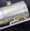
Because I didn't want to scribe the boiler, leaving marks that might show through the paint, I thought that I might be able to use the dial test indicator attachment to hold a pencil. Sadly all the pencils that I could find in the house were all the standard hexagonal type which were all too big to fit in the holder. Having a box of brand new pencils to hand I had no problem in turning the end of one of the pencils down to fit the DTI holder.
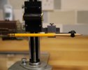
53614598884_42277ff922_b.jpg

I used a flat ended HSS tool bit and although I have a corrugated way cover I immediately vacuumed the sawdust off the lathe to prevent any staining of the metalwork.

I sat the loco on a pair of 1-2-3 block on a sheet of plate glass to do the marking of the horizontal line down either side of the loco.
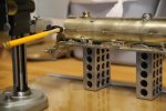
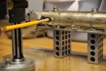
53614599794_4555d681e6_b.jpg

53613392187_1fe709b326_b.jpg


Since taking the photos I have chopped off the thinned down end of the pencil and it now lives in the box with the height gauge as I suspect that over time I will make much use of it for marking boilers.
 

Rob Pulham

Western Thunderer
Progress over the last few days has been excellent so much so that I have backtracked a little and picked up on a couple of items that Paul has mentioned in the past.

The first was to replace the hatch knobs on the footplate with some wire loop examples. The knobs have gone in the spares box and will come in at some point.

53621836947_e99e722425_b.jpg

The next was this comment from Paul, which I completely agreed with as I had been unhappy with the fit for sometime. But, I wasn't sure how to go about rectifying it then, so I slept on it...
Hello Rob,

when are you going to sort out the gap between the chimney and the smokebox?

Coat on and the door closed very quietly behind me!

OzzyO.

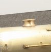
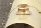
The (replacement for the kit provided) chimney was cast from a 3D print by Mike Hopkins and Mike had placed his print supports under the bottom rim. I can see why as they would be least likely to be seen on the finished model. However because the casting also had a tube which fits into the smoke box to aid location, it made cleaning up the bottom rim and getting it to fit flush very difficult.

This is what it looked like after my initial cleaning up of the remains of the supports

52475604315_00642ef207_b.jpg

Having almost finished the body work, I took the bull by the horns and took the chimney back of back gently gripping it in the vice between two pieces of round bar while applying heat to the inside of the chimney until I was able to ease it off.

53623179265_50768332bc_b.jpg

Although I took photos long the way, I am not going to share how I machined the chimney just yet as I want to use it as part of my an evening with presentation later in the month.

53622919398_4f663d7b56_b.jpg

This is it refitted to the smokebox.

53623164195_97c94c8785_b.jpg

53621833747_4ff41e9194_b.jpg
 

Rob Pulham

Western Thunderer
Although I had fitted the handrail knobs to the boiler and smokebox earlier last week, I hadn't added those on the resin firebox. This was for no other reason than the superglue was upstairs in the fridge and I thought it easier to crack on with something else and bring the superglue down later.

When I did subsequently fit the remaining knobs in place, those on one side were fine but for some reason both on the other side didn't seat properly and the glue set as I was trying to push them home. I tried pushing them in with pliers and gently tapping them but I was very concerned that the resin firebox might crack if I was too vigorous. They didn't stick out by much but I wasn't happy having put so much effort in with re-seating the chimney etc. It was during commode time (a term picked up from an american machinist who I watch on Youtube) that an idea came to me.

This morning in between making the end caps for the handrails I plucked up the courage to give it a go. I got a short offcut of the 0.8mm piano wire that I have made the handrails from and put a small bend on one end gripping the wire in a pin vice just in front of the bend.

53624064627_5f616b6382_b.jpg

I popped the bent end through the hole in the first offending handrail knob. I chose the one that was furthest in, to try the proposed solution on. Then I connected the negative terminal of my RSU to the piano wire which protruded from the handle end of the pin vice. A quick touch with the probe and a slight twist and the knob thankfully popped free without issue. Buoyed by this success, I repeated the same on the second offending knob and I had barely touched it before it popped out.

As a precaution because I was heating superglue/resin I had the extractor fan running at the side of my bench just in case any fumes were created. I was probably being over cautious as the glue just seemed to slightly soften rather than melt.

Then it was a simple job to re-drill the holes making sure that the knobs were a loose sliding fit before attempting to apply more glue. It was at this point that I found out why one of them wouldn't seat properly. There was a slight rim around the shank on one which prevented it from seating flush. It wasn't really visible but when I ran my nail across it I could feel the ridge. To save time I swapped it for another one from the stores and both were fitted properly.
 

Rob Pulham

Western Thunderer
The last items to make for the Princess, are the cylinder drain cocks/pipes. The castings were missing from the kit and I looked at those offered by Laurie Griffin and Ragstone but I wasn't convinced that they were suitable for use on the Princess and decided to make my own.

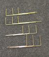
They are not yet complete but this is the first step. The making and alignment of the pipes themselves.
I made a jig from a strip of nickel sheet which I milled a series of grooves in. The grooves were milled to suit the etched holes in the bottom of the cylinders with spacing of 10mm and 9mm

I milled them using the point of a countersink bit and supported the material with a shop made machinist jack.

53627083361_3e36e5f71b_b.jpg

I did the same on each end of the strip of material to give me a top and a bottom for the jig.

53627527325_a3cf68222b_b.jpg

The two half of the jig were loosely placed together and the legs of the pipes fed into them and the engineers clamp tightened to hold the horizontal parts together. A small G Clamp and a hair grip made sure that the pipes were vertical to each other and couldn't slip while I soldered them.

53626187587_134448ee36_b.jpg

I wasn't really concentrating when I cut and bent up the pipes and I ended up with enough for two pairs. To compound that minor error I had placed them in the jig the wong way around and I had the 10mm and 9mm gaps the wrong way around. I could have unsoldered them but felt it was easier to cut some more and add these to the spares box.

53626187677_dfcc2bcf4a_b.jpg

I cut these a little different and left the outflow end of the pipes a bit long to cut down when fitted.
Oddly when I put these in the jig the other way around I didn't need the G Clamp, the engineers clamp was sufficient to hold them in place.
 

Rob Pulham

Western Thunderer
I asked a fellow modeller if he had fitted the cab roof yet, because it too has been yet another challenge to overcome.


The reason for the challenge is that the profile of the roof rib visible in the shot of the roof below is a different profile to that of the rear frame of the cab which supports the cab roof at the back.

52524961669_abdeaa9a83_b.jpg

When I first fitted it the front of the roof didn't go anywhere near the front of the cab (it did fit when I first "rolled" it some time ago. To get around the issue I cut a front rib to fit just inside the cab front which brought the front of the roof into the right shape again

53629459905_179ffc2ded_b.jpg

This left a gap in the middle of the roof at the rear which I filled with solder (just visible in the photo below as is the additional rib at the front of the cab). Not very elegant but it works.

53629217793_8d48346272_b.jpg
 

Dave Holt

Western Thunderer
Yes, Rob, Stanier roof profiles are not the easiest profile to get just so. You look to have got it pretty well sorted and the extra front rib is a good solution and will be barely visible once the backhead is in place.
It does look as if the inner steam feed to the vacuum ejector is missing?
Dave.
 

OzzyO

Western Thunderer
Hello Rob,

nice job on fitting the chimney. I bought one of these a bit back for about £70
post-8920-0-64102900-1438503131_thumb-jpg.72866


There is more info in this thread by myself that could be helpful to you.

.westernthunder.co.uk/threads/anne-and-me-in-7mm-from-the-d-a-kit.4611/page-2#post-121549

If the link doesn't work. It's in area 51, "Anne and me in 7mm from the David Andrews kit".

The loco is coming along very nicely.

ATB

OzzyO.
 
Last edited:

Rob Pulham

Western Thunderer
Hello Rob,

nice job on fitting the chimney. I bought one of these a bit back for about £70
post-8920-0-64102900-1438503131_thumb-jpg.72866


There is more info in this thread by myself that could be helpful to you.

.westernthunder.co.uk/threads/anne-and-me-in-7mm-from-the-d-a-kit.4611/page-2#post-121549

If the link doesn't work. It's in area 51, "Anne and me in 7mm from the David Andrews kit".

The loco is coming along very nicely.

ATB

OzzyO.
Thanks Paul,

I do have a boring head and a set of boring bars, which I confess that I haven't had cause to use yet. Mainly because when I bought it I inadvertently bought it with a tang on the taper rather than a screw for a drawbar. Once I realised that, I bought a different taper section so I can now use it in the mill. I have used the boring bars in the lathe but I hadn't thought of using the boring head instead of the fly cutter. I will have to give it a try.

In theory it should make it easier to workout the radius of the cut but for me setting the radius of the fly cutter isn't too difficult because late last year I fitted digital readouts to all the axis. So once you have found the edge of the bar and centred the quill over it. It's a simple matter to move the X axis to the required boiler radius and then push the tool bit against the workpiece to secure it at the correct radius.
 

Rob Pulham

Western Thunderer
Today saw the last of the tiny components that make up the cylinder drain pipes made and assembled. I also ended up with a nice little bag of extra nuts. I made six for the operating bar and then decided they were a little big (lengthwise) so I made some smaller ones.

Each one is made from 16 individual parts and the valves are a bit of a work of fiction because I couldn't find any clear photos of what is actually under there but they pass muster when compared to the castings that I have in various kits and at least they fit this particular loco.

The clips that hold the pipes together are still loose and able to slide along the pipes at the minute until I get them fitted and can determine their final position.

53633313576_457a9680b4_b.jpg
 

Rob Pulham

Western Thunderer
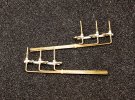
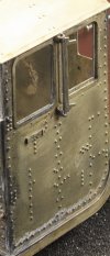
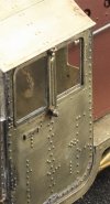
The last parts to be made and fitted are the cinder guards that fit on the cab side. Even though they are nickel on this kit, they are very vulnerable and a friend mentioned that he always models them folded back which seems like a good idea. but I was concerned about painting around them. I also had the idea that I would like them to fold in like the real thing and so I decided to experiment with the extra etched frame that David supplies.


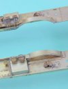
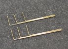
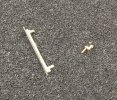
I cut off the two pegs that fit into holes etched in the cab side and soldered a length of 0.5mm piano wire on the back of the frame. Then I drilled a length of 2mm x 2mm brass angle at the ends and soldered in some filed down brass dressmakers pins which I cut down to fit through the holes in the cab. I then drilled the other leg of the angle to accept the pain wire and once soldered to the cab it folds back just like the real thing.


Having got the first one fitted I made up the second. Which I took a photo of. Keen eyed readers will note, that there is only one bracket. Sadly, the second made a bit for freedom as I was shortening the peg after a test fit. So unless a miracle happens I will be making up another.

53639875550_68334b7287_b.jpg

53639636353_5d7cda8efb_b.jpg

53639755859_7afc9b537e_b.jpg

53639755924_dd5afabb92_b.jpg
 
Top