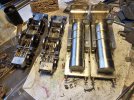
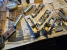
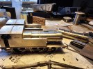
Nick Dunhill's Workbench - Cambrian Railway 2-4-0T Albion Tank

Nick Dunhill

Western Thunderer
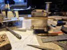
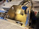
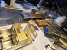
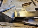
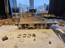
It's time for a new project, and this is a very esoteric one indeed. It's a Cambrian Railway Albion Tank. The CR bought 12 2-4-0 tender locos from Sharp-Stewart in the 1860s (and so did the Furness Railway, which is the origin of the GA I have used.) They chugged around for quite a while, aquiring new boilers and better brakes etc, and in 1907 two were converted into tank locos and ran on the Barmouth to Pwllheli line. These are the two locos I am building, nos, 44 and 56.
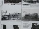
52874683906_445ce59e2e_b.jpg

Taff Vale Models have recently introduced a kit for the tender version of the loco, I have been sent a set of custom etches from Julian at TVM ordered by my client to build the tank version. The build is to be an all singing and dancing model.

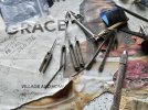
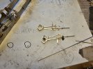
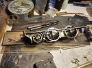
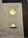
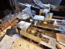
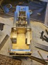
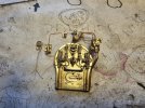
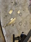
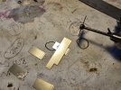
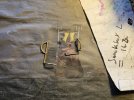
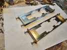
The first step was to build a footplate. The locos had a wooden buffer beam at the front and the custom etches had a series of brass overlays that were designed to be planted behind either sides of the buffer beam to give the illusion of a wooden plank. I didn't much like that so got a local joinery to cut some wooden ones from a left over lump of mahogony (from a sustainable source of course!) I modified the buffer beam etches to suit. The etches had no castings included but luckily Markins (via Roxey Mouldings) do some rather nice turned ones. These were modified slightly to be self contained.
52872918855_3459cea532_b.jpg

The wooden bits slot in and out so they won't get wet when neutralising acid fluxes after a soldering session.

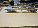
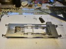
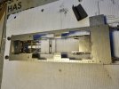
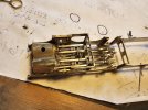
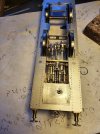
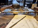
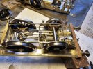
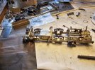
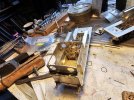
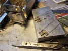
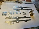
The next but was to make a chassis. The chassis frames supplied were fine, but the stays were only 24 mm wide (with cusps) which would have resulted in a chassis only 25 mm wide. This is far too narrow to fit inside motion, and also the kit stays were a bit randomly placed. I cut out some more with a better representation of the rear drag beam and cylinder block.
52871958507_f32d08268c_b.jpg

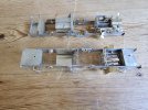
Next week I have to build a pair of chassis and incorporate the slide bars and crossheads.

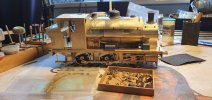
Here's an interesting little loco I have been building on the side for someone.
52874886044_75de9789cf_b.jpg

It's a GWR 2196 class built from an Agenoria kit. As is usual with Agenoria the kit was a delight to build. Everyone should build an Agenoria kit at some stage, they fit together very nicely, especially for a hand drawn kit. It's at paint now.

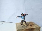
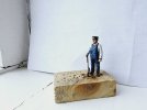
Also noteworthy are the crew I bought from Andrew Stadden and had painted by Evan Griffiths. Evan is really a Wargamer/D&D(?) guy but does excellent paint jobs on my crews. All properly researched etc. (evilevan666@yahoo.com)
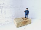
52875125598_fd879dba5d_b.jpg

52875125423_ed98304044_b.jpg

Skeggy anyone?
52875064935_5a5c481e6c_b.jpg
 

Nick Dunhill

Western Thunderer
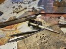
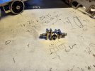
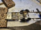
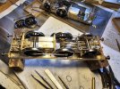
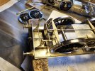
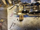
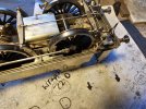
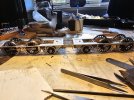
I spent a lot of this week sorting other locos out and going too and fro from the painter. I did however make up the rear drag box and cylinder block and made a chassis. I pored over the drawing I have and measurements showed the Slater's cast brass axleboxes to be an almost perfect match for the ones on this loco. They required a little bit of modification round the front wheel and some fettling to make them fit nicely. Surprisingly the bearings were a nice sliding fit in most of the cast horns. I used solder on the horn cheeks to take away any end float and have used those cast horns for the front wheels. The LGM motion kit has slide bars that are very close match, but they did require a fair bit of fettling and straightening to make them function smoothly.

52891522992_19ca8744ab_b.jpg

The crank castings had a crank throw that was too big and therefore the slidebars wouldn't contain, luckily Laurie had some that were near perfect, so I have swapped mine. I managed to work out how the Stephenson link motion works (with the help of an engineer!) It is very similar to the arrangement that Broad Gauge locos had (and I have built a few of those in the last couple of years!)

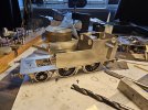
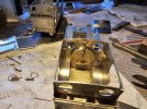
So here's the chassis with the slidebars test fitted and the footplate on top.

52892550918_93e99fe41f_b.jpg

52892095211_c02f9c4abc_b.jpg

52892486140_eaa634d1d7_b.jpg

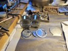
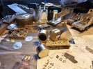
Here's how I aligned the cylinder covers on the cylinder block, it's a cocktail stick with masking tape wound round to achieve the correct diameter. It reminds me of a clutch alignment tool I made years ago, from a bit of broom handle and some parcel tape, when fitting a new clutch and refitting the gearbox on a Reliant Scimitar I owned for ages in the 90s.

52892095346_05270e3190_b.jpg

Also I have misplaced my 6'' rule somewhere in the workshop/house and it is driving me potty!
 

simond

Western Thunderer
Nick, several points:

thanks for the tip about solder “packing” on hornways. “D’oh”. Why didn’t I think of that?
Reliant Scimitar. Never owned one, but the landlady let me use hers (ooh er, Missus). Great fun. Didn’t like the piano key switches. Scared myself stupid one night by turning the lights off, rather than the wipers.

Never needed the wrapping masking tape trick, but I’ll remember that one too!

atb
Simon
 

Nick Dunhill

Western Thunderer
Recent events took priority over work for a couple of weeks but I'm back at the workbench, and my 6'' rule reappeared!

I have been making the inside motion, primarily from a LGM kit, but a lot has had to be made by hand, I will explain. These locos have a very old style of Stephenson link motion with the expansion links between the slide bars and the lifting links attached to the bottom pivots if each expansion link. It is a similar layout as GWR broad gauge stuff. The LGM kits are designed for a more 'modern' layout of the system.

Because of the constraints of Fine Scale the cylinder centres have to be closer together than would be prototypical. This is because the chassis is much narrower than the real thing. Therefore there isn't a lot of room for the expansion links, eccentric rods and lifting links. I used the eccentric rods and straps in the kits and made the rest.

53017812055_0325bec8f9_b.jpg

53017422731_f7f6d18d29_b.jpg

53017422631_99b3a5b5db_b.jpg

53017808405_6962c71c00_b.jpg

You can see in the last photo that I closed up the cylinders (the hole is to drop a chassis fixing screw into. There's a tube that makes the screw land in the hole.) Next week I will complete the lifting links and hopefully make crank axles. I should have working motion then I can refine the chassis a bit more.
 

Nick Dunhill

Western Thunderer
So this week I made some crank axles and fitted up the inside motion. All worked well first time so I'm pleased with that.

53028995652_598c97fe02_b.jpg

53029577901_f4353fb253_b.jpg

53030064458_230f74d159_b.jpg

Next job was scratchbuilding fireboxes bottom and ashpans. These were installed in the chassis.

53030064443_d2bb81fe09_b.jpg

New guard irons were cut out and installed, the front wheel splashers formed and fitted and some of the brake gear went on.

53030064518_60fa0c4e00_b.jpg

Next week I should be able to finish the chassis and crack on with the bodies.
 

Nick Dunhill

Western Thunderer
This week I have soldiered on with the chassis. They now have cylinder drain cocks and all the reach rodding and the brake trunnions and cylinders have been made and fitted. Some 3D printed sandboxes have been fitted and all the parts for the sand pipes cut out ready for monday. I made a start cutting out all the body panels and fitting some of the beading from round the cab openings.

The etchings for the bodywork look good so hopefully I'll burn through the rest of the build quite quickly.

53045665914_b093976bc8_b.jpg

53045873395_f8919acfc4_b.jpg

53045979643_330e018ba8_b.jpg

53045873615_e4cd19e505_b.jpg

Everything has been test fitted here, and happy to say that I have 2 very free running chassis and inside motion

53045873760_8e93673a1d_b.jpg
 

Nick Dunhill

Western Thunderer
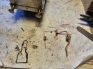
It looks on the surface as if I was a lazy arse last week, but I did a fair bit! I completed the sanding gear. I had no castings for the shoes in the sanding pipes, but I did cut up some sand pipe castings in the LGM range for the U-bends. I scratchbuilt the shoes out of thin walled tube. Each shoe was in 5 pieces plus the pipes themselves. You can see in the pictures that the front sand pipes have slightly different arrangements on each loco. The copper steam pipes extend from the shoe and disappear between the ashpan and frame on their journey to the control valve on the backhead. Very small p-clips were made from rivetted strip to locate the pipes on the sides of the frame.

53063242008_e95781380c_b.jpg

53062752941_22d9cbe781_b.jpg

You can see part of my shopping list for Hobby Holidays in the foreground!

The picture shows the way I have mounted the springs and hangers on rods attached to the keeper plates, or soldered directly to the bearings. The springs and hangers are very nice 3D prints from Mick Davies but are not very structural without support.

Having (almost, pickups and motor to go) finished the chassis I turned to the bodies. I cut the etches for the cabs and bunkers and soldered the beading round the cab openings. The positions of the windows in the cab front and rear didn't look quite right. When compared with the drawings I have it it became clear that the cab front, and rear and bunker rear etchings were too narrow by 2.3 mm.

53062937614_860a507b97_b.jpg

53062976859_30ea5fd2bb_b.jpg

So the only solution was to cut some more. I also added more cab side beading round the front and rear of the cab and the coal hole (coyl oyl as us northerners would say) on the cab rear/bunker front. They have all been cut out but I forgot to take pics and now I'm on 'holiday' in the North isles! Sorry
 

Nick Dunhill

Western Thunderer
Back on with the show this week. The first job was to attach all the beading to the cab sides. It goes round the top of the bunker, along the top of the water tanks and round the cab opening. The latter is very tricky as the handrail holes at the ends of the beading have to be centred on either side of the cab door. This will ensure that the cab handrails are evenly spaced. Luckily the beading strip for the cab opening was exactly the right length.

I cut out new cab fronts, bunker rear and 3 parts to make each cab rear. The cab rear has a separate upper section, with the window holes, a bottom section, with the shovel plate and hatch, and a section in the middle to join the two. The middle section has a fold in it to match the shape in the picture I have of no 44. I soldered the cab front and lower rear to one of the cab sides, and attached the other side by standing the whole assembly on a flat surface to ensure everything was square. I then tacked this sub assembly to the footplate, and when happy it was centred and close enough to the rear of the footplate, soldered in place. The footplate was screwed to the chassis first to keep it flat. The bunker rear was cut from 0.25 mm thick sheet and was higher than needed to aid forming the curve. This was done round a suitable diamerer screwdriver and then it was offered up to the sides and cut to the required height.

53094069887_85620ba95e_b.jpg

I layed beading across the back of the bunkers to meet the side pieces already attached to the cab/bunker sides. The coal rail stanchions were etched items provided, but had to be modified slightly to fit the corners, and were attached to the bunker tops. The coal rails were recovered from the tender coal rail etch from my ACE Kits NBR Atlantic build (https://www.gaugeoguild.com/xenforo...nbr-reid-atlantic-from-an-ace-kit.9457/page-2) so at least another small part of the ghastly ACE kit has been useful. They were attached to the stanchions thus, using a strip of waste etch as a jig.

53094638271_d40bf6b9c9_b.jpg

Bunker finished, I moved on to the cab. Of course because I had widened the whole body the etched cab floor and splashers were the wrong size. I fabricated a new floor and splashers with the interior strengthening angle.

53094812759_88f357e2a9_b.jpg

53094069997_99eed42f3f_b.jpg

The handrails for the cab were fitted up. I made tapered cab handrails from 0.9 mm nickel silver rod by spinning it in a mini drill and laying the spinning rod on a bit of wood. The rod quickly makes a groove in the wood that can be used to file a taper in the rod. I attached the wood to my bench with double sided tape to stop it wandering away when I was filing the rod. Ferrules were made, from thin walled tube, for the top and bottom of the handrails and the footplate drilled to accept the bottom of the handrails. In this way the handrails are detachable for paint.

53094070277_2e4fa32be1_b.jpg


The grab rails for the cab sides also need to be removable for painting. To facilitate this I opened out the etched holes in the cabside to 1.0 mm and let into them some thin walled tube as detailed here;

53096540086_a8269314f8_b.jpg

The hex end was on the inside, and 0.8 mm diameter nickel silver handrails were located through the bits of tube. In this way the handrails were a push fit in the cab sides and the inside looks like small nuts screwed over the ends of the handrail to locate them. See picture above.

53094070327_f0692f02bc_b.jpg

You can see in these photos how I installed the floors for the cab and all the internal splashers. There's also a representation of the tops of the chassis frames at the side of the splashers, and a well was made at the front of the cab floor to accept the backhead and pipework. Of course now I've widened the whole bodies the cab roof etches will be too narrow and I'll have to make new ones, and that will be my next task.
 
Last edited:

P A D

Western Thunderer
Top class scratch building as always Nick.

That's a neat trick to make the grab rails removable, which I will steal for use on my Stanier Mogul build. The grab rail low down on the tender side would make adding the lining awkward, so seeing your solution is timely. I'm all for making the painter's life easier with detatchable boilers etc, especially when the painter is me!
Cheers,
Peter
 
Last edited:

Dan Randall

Western Thunderer
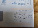
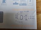
Hmmm, I can’t help thinking, that your sketch is on the wrong side of the envelope… :))
IMG_3759.jpeg
(Great idea for the handrails though). :thumbs:


Regards

Dan
 
Last edited:

Nick Dunhill

Western Thunderer
Hi Dan
Possibly I was a bit bleary this morning when I drew it. Not a threat to national security though, just a council tax query.
Nick
 
Last edited:

Nick Dunhill

Western Thunderer
Another week of joy and hard work in the Dunhill workshop has passed, and many podcasts listened to.

As I alluded to in the last post, first call was to make new cab roofs. There were enough bits and pieces in the etches to add the strips that fit round the tops of the cab sides, front and rear, but the cab roof etch was now too narrow. I cut new ones from 0.3 mm nickel-silver and curved them to the correct profile. The undersides of the panels were heavily scored on the edges to allow the flip-up gutter to be formed. The folding puts a lot of rigidity into the roof panel, and the ribbing provides the rest. As you can see there's bits of extra ribbing at either end to locate the roof accurately, and so that it can be removed for paint, and later, admiration of the interior. There was an etching for a roof vent but I couldn't see one in any of my pics. Presumably not fitted to keeps the Welsh aqueous sunshine out!

53109197684_b4a4b2797f_b.jpg

53108991476_f5b06b3ec8_b.jpg

I let some bits of tube into the roof to locate the whistle, and added a whistle pull.

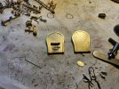
Next was the backhead. I scratchbuilt backheads as I couldn't find any close in LGM and other ranges. It's a front with an overlay for the polished surround, and sides made from strip bent round the perimeter. The coyl oyls were scratchbuilt too.

53108420922_6e60d2b195_b.jpg

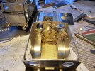
I then started adding all the castings to the backheads. The steam turret was scratchbuilt but most of the rest is from LGM, or left-overs from other builds.

53109198174_ecc03ec388_b.jpg

53109198264_5ed296ba2c_b.jpg

All the backhead fittings are made to be removable for painting.

53108421337_92a0aa0d89_b.jpg

It was at this stage that the nice Mr Rhodes of this parish sent me a photo of no 44 that I hadn't seen. It showed that the water tanks extend up to the cab door and not the cab front as my info had suggested. Imagine the lip-biting and expletive swallowing that went on knowing that next week I'll have to modify the lot. Oh, and the firebox formers supplied are the very wrong shape, luckily I guessed that and didn't make the backhead the same pattern. Ying and yang, the universe will balance itself in the end, and nice Messrs Campbell and Stewart will still drone on in the background. Happy days!
 

Nick Dunhill

Western Thunderer
Bang

53124475967_8e48d369d8_b.jpg

We could end the post there, but I actually did a lot of fabricating this week. I discovered that the etches I an using have their origins in 4 mm and as a tender version of the loco. The etches were blown-up to 7 mm, with a few modifications, and then this artwork was adapted to become the tank version. The 4 mm origin is evident in the design of the water tanks. There were no inner sections or splashers to the water tanks, and some assumptions had been made about the shape of the firebox which I thought weren't quite correct. I have to confess that I based my assumptions about the firebox on my previous Cambrian Rly Wrexham tank builds (https://www.gaugeoguild.com/xenforo...hills-workbench-cr-0-4-4t-wrexham-tanks.5456/) assuming that the boilers would be similar given they were built by the same builders, Sharp Stewart, at about the same time. The fireboxes are egg shaped, and not circular in profile (all will become apparent when I build them in a week or so.) This gave me a measurement that I could use for the overall width of the fireboxes and therefore the width of the water tanks. I mocked this up and it looked very similar to a photo I have, the gap between the inner front edge of the water tank and boiler looked about the same on model and photo.

Of course the real loco would have had splashers built into the water tanks to clear the wheels, and there were no etches in the 'kit' for these. I set about fabrication them on a rainy saturday afternoon, hoping to get half a day off in lieu to ride my moto on the next sunny weekday. I didn't take many photos, but you can see the splashers and tank top and front in this photo. The void was filled with lead sheet and the inner panel cut to close the tanks.

53125475110_a100b4e8f7_b.jpg

53125475115_fdc77fa5bb_b.jpg

You don't see much of the splashers from the top, but if you turn the loco upside down the inner sections of the splashers are there. That was what I was hoping to achieve. In the next photo you can see the parts cut out for the portion of the tank inside the cab as mentioned in the previous post.

53124475632_00fc9f585f_b.jpg

And here they are assembled.

53125557953_da71e3a9a7_b.jpg

And here's all that modified pipework and backhead fittings.

53125558293_0b7491b449_b.jpg

53124476092_251d88a38c_b.jpg

53124476322_789310c5a8_b.jpg

The above photo shows the layout of all the backhead components.

I thought I'd make the steps to end the week, they are a nice easy task to let myself gently into the weekend. However the etches had a multitude of inacuracies, and the half etched rebates on the underside of the footplate to locate the front steps was too far back. Lots of modifications were done.....

53125279654_10f623f144_b.jpg

In the foreground you can see the cab steps. Their backing plates turn in at the top and are mounted on a structure yet to be determined. The following pictures show how I engrave a fold line in a sheet of metal to get a crisp fold, in the way that etched kits work.

53125075431_6d25083b64_b.jpg

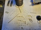
This picture isn't very clear, but essentially I've scribed a line where the fold should be and soldered a straight bit of waste etch just below the line as a guide for the slitting disc.

Then I run a slitting disc a few times along the guide until I have a groove deep enough to form a fold line.

53125279469_0b06feaf07_b.jpg[/url]

Then I folded up the step backing plate and attached the treads. Next time I'll have figured out why the step treads turn in and made something to achieve this.
 

Nick Dunhill

Western Thunderer
I found some C section brass that was exactly the right dimensions to attach to the etched cab steps and then solder to the underside of the footplate to give the effect in the photographs. Also I spent quite a while making the vacuum pipe that runs from end to end of the loco, with a connection on each buffer beam. I assume the loco has a steam brake and the vacuum brake is for the train. The swan neck parts are modified Laurie Griffin Castings, and the pipe is bent from 1.6 mm brass rod. All the elbows are made by slash cutting 1.8 mm OD (1.6 mm ID) thin walled tube at one end and cutting to length at the other with a scalpel. I push a 1.6 mm drill into the end of the tube and roll a scalpel over the tube to cut it. The drill prevents the tube from collapsing but it does blunt the scalpel blades quite quickly, which require re-sharpening with a slitting disc in a mini drill (or similar.) Each elbow has two lengths of slash cut tube.

53171071779_baa174c478_b.jpg

53170288247_7f01bd4df0_b.jpg

53171363198_32142d8326_b.jpg

The swan-necks push onto the end of the end to end pipe and are detachable for paint. Also if you don't solder or glue them firmly on final assembly they simply rotate or drop off if bashed, preventing further damage. The P-clips are made from left-over bits of boiler bands, bent round a suitably sized drill. I scratchbuilt water filler lids and sandbox lids.

The last week has been spent cutting out formers and wrappers for the firebox, smokebox and boiler. I had some hopes that the etchings provided would yeild some useful parts, but they are all in my scrap bin.

53170863866_086551e1dd_b.jpg

53171298815_ea145fa5a7_b.jpg

53171059444_41793d0a0c_b.jpg

53170276647_5107db75bf_b.jpg

Next job will be to connect them up and add the brass covers between boiler and somkebox and boiler and firebox.
 

Nick Dunhill

Western Thunderer
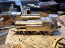
A lot of time was spent fixing the 3 elements of each boiler assembly together accurately and forming the brass finishing strips between each.

53189275781_d5c7ea51b8_b.jpg

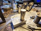
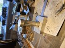
To align the three components accurately I lay the firebox, on it's rear, on a flat bed. In my case its a block of aluminium, and the boiler is positioned on top of the firebox . A weight is put on top of the boiler, as it stands vertically on the firebox, to minimise movement. A square is placed close to the firebox sides and top to make sure the boiler sits squarely and centrally on the front of the firebox. If any adjustments need to be made, the faintest blob of solder can be diplomatically placed on one of the mating surfaces to make the boiler tilt. When satisfied with the position I tack the two elements together and move on to stacking the smokebox on top and repeating the process. This way the boiler doesn't wander off to one side of the loco when positioned on the footplate. The join between the smokebox and boiler has a brass ring round it. The ring is formed from a 1 x 1 mm length of square rod bent to form a circle (round a large diameter bit of steel bar) that fits nicely round the end of the boiler. This is radiused and slid up to the join with the smokebox. All is soldered up with low melt lead solder.

The brass finishing piece between the firebox and boiler is similarly made out of 2 x 2 mm brass bar. It only really needs to be a horseshoe shape, as the bottom bit disappears behind the water tanks. It's roughed out with a saw and radiused, then soldered up against the front of the smokebox. It can be finished in position very carefully with a sanding disc, taking care not to scar the firebox wrapper. Boiler bands were added.

53189341619_4985c5c85d_b.jpg

It does take some time and care to get everything neat.

The next job was the stay that sits on the tank tops and round the top of the boiler. The etches supplied were oh so close, but......

53189638018_1ea5ff1d78_b.jpg

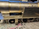
The model now has an inspection hatch in front of the smokebox and some finishing strips down the side of it. The 3D printed suspension springs for the front wheels were added. Lots of holes have been drilled to accept things that will be added post-paint, such as lubricators, and some balance pipes between the front bottom corners of the water tanks were made.

53189276001_be2fbc96d6_b.jpg

The last job of the week was the ejector pipes running down the RHS of each boiler. They were a pig to get right! The pipe runs between the boiler and tank side then up to the cab front and is not a job to do on a friday afternoon.


53189360776_1233536d24_b.jpg

Should finish next week.
 

spikey faz

Western Thunderer
A lot of time was spent fixing the 3 elements of each boiler assembly together accurately and forming the brass finishing strips between each.

View attachment 195757

To align the three components accurately I lay the firebox, on it's rear, on a flat bed. In my case its a block of aluminium, and the boiler is positioned on top of the firebox . A weight is put on top of the boiler, as it stands vertically on the firebox, to minimise movement. A square is placed close to the firebox sides and top to make sure the boiler sits squarely and centrally on the front of the firebox. If any adjustments need to be made, the faintest blob of solder can be diplomatically placed on one of the mating surfaces to make the boiler tilt. When satisfied with the position I tack the two elements together and move on to stacking the smokebox on top and repeating the process. This way the boiler doesn't wander off to one side of the loco when positioned on the footplate. The join between the smokebox and boiler has a brass ring round it. The ring is formed from a 1 x 1 mm length of square rod bent to form a circle (round a large diameter bit of steel bar) that fits nicely round the end of the boiler. This is radiused and slid up to the join with the smokebox. All is soldered up with low melt lead solder.

The brass finishing piece between the firebox and boiler is similarly made out of 2 x 2 mm brass bar. It only really needs to be a horseshoe shape, as the bottom bit disappears behind the water tanks. It's roughed out with a saw and radiused, then soldered up against the front of the smokebox. It can be finished in position very carefully with a sanding disc, taking care not to scar the firebox wrapper. Boiler bands were added.

View attachment 195758

It does take some time and care to get everything neat.

The next job was the stay that sits on the tank tops and round the top of the boiler. The etches supplied were oh so close, but......

View attachment 195759

The model now has an inspection hatch in front of the smokebox and some finishing strips down the side of it. The 3D printed suspension springs for the front wheels were added. Lots of holes have been drilled to accept things that will be added post-paint, such as lubricators, and some balance pipes between the front bottom corners of the water tanks were made.

View attachment 195760

The last job of the week was the ejector pipes running down the RHS of each boiler. They were a pig to get right! The pipe runs between the boiler and tank side then up to the cab front and is not a job to do on a friday afternoon.


View attachment 195761

Should finish next week.
Nice!

Mike
 
Top