P48 for Cotton Belt: Roster addition SW1200

SSW GP9
  • Yorkshire Dave

    Western Thunderer
    Well, I've finally taken the plunge into P48 for my US O scale. Next stop Anorak Central.

    I've had a Red Caboose GP9 floating around for a few years and whist clearing out unwanted HO stuff I looked at the GP9 which which promptly whispered 'build me next'. After checking the kit I found the original gears had split so I ordered a replacement geared wheelset from North West Shortline albeit to O gauge 115 tread (however, there is room on the axle to close this to P48). I wanted the track gauge to be exact for 1/4'' scale and after much umming, erring and trawling through various P48 websites, P48 it is to be.

    Trackwork will be handlaid code 100 to represent a branch line. Just need to decide which method - copper clad and solder (easy) or spikes and tie plates (????). I've still yet to order the switch parts but the rail is on order though.

    I have also acquired several items of rolling stock including several boxcars to convert to SSW prototypes. The biggest conversion is to the Chessie International Car wide vision caboose. Effectively converting it from a Eastern road version to a SSW version which already means windows to move or blank out, cupola to raise, verandah end to rebuild etc etc.

    I have at least made a start with the GP9. Knowing there was a sagging problem with the chassis, and after much discussion, I decided to strengthen the existing chassis with 3mm brass angle. The plastic chassis was effectively sandwiched between the brass angle and held together with superglue and 1mm machine screws.

    Top
    020 GP9 chassis.jpg

    Bottom 021 GP9 chassis.jpg

    The angle protruded into the truck mounting hole so I filed some of the brass to widen the hole but kept at least 1mmof the angle to preserve the strength. No more sagging chassis though.022 GP9 chassis.jpg
    023 GP9 chassis.jpg

    While messing about I also ordered loads of wheels and working knuckle couplers from Protocraft. And loads of decals and boxcar parts.

    At present I'm using the new Atlas trucks which are closer to scale and the differences are noticeable. The old truck and wheels is on the left and the newer truck with the P48 wheels is on the right.

    009 Atlas trucks.jpg
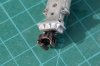
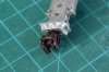
    As for the couplers. This is an assembled version with a working cut lever. I have also put a small piece of steel wire in the top of the pin to enable a stick with a magnet on the end to be used. And it works. Good old 7mm British handrail knobs are used for the cut lever bracket.

    008 Working knuckle coupler in closed and locked position.jpg

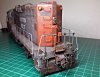
    And the GP9..... will be good old Cotton Belt weathered bloody nose finish. More will follow.... and loads of research into boxcars which is a subject in it's own right.
     

    Attachments

    • 006 Coupler closed.jpg
      006 Coupler closed.jpg
      302.9 KB · Views: 23
    • 007 Coupler open.jpg
      007 Coupler open.jpg
      278.5 KB · Views: 22
    Couplers, Trucks
  • Big Train James

    Western Thunderer
    Mickoo - thanks for the picture of the coupler - now to order some Albion Alloys sleeved brass square tube and brass strip to make my own coupler draft boxes.

    You'll need a large pair of spiking pliers for those spikes :D.


    My period of modelling will be 1980s which means I can have some of the older cars but I'm interested in pictures of draft gear (normal and cushion) so I can at least attempt to get mine right.

    Also I've noticed from the pictures modern cars (other than the double stack and possibly autorack) appear to run on 36'' wheels rather than 33''. Is this the case now or does it only apply to heavier tonnage cars?
    [/QUOTE]
    To my understanding, there are four common sizes of modern wheels in use. I would think "modern" in this sense includes the 80's, as most everything we see now was already around by then except for most of the articulated cars. I believe most modern wheel standards were in place by the late 60's to early 70's. Not much has changed since then.

    28" wheels I believe are used on Autoracks at a minimum, accounting for clearance concerns rather than load ratings.. There may be some other high clearance cars that require them, but none to my knowledge as ubiquitous as the autoracks.

    33" wheels are generally considered for cars with 70 ton load capacities, although I think some of these cars may also use 36" wheels. About the only 70 ton capacity cars I know of now are boxcars, and possibly flat cars. Typically cars whose ladings are large in volume but light in mass. Like car parts or appliances. Or wind turbine blades. Going back to the 80's, 70 ton cars are almost certainly more common. I don't know the dates, but through the years the maximum tonnages have been incrementally increased as cars have gotten larger.

    36" wheels are probably the most common today as they are the defacto standard for 100 ton cars. Larger boxcars, most any hopper, covered or otherwise, tank cars, gondolas, and so on.

    38" wheels are much less common. They are typically on equipment rated for 125 tons. They might be found on the common truck found between two articulated stack or spine cars, and therefor carry some part of the load from both cars.

    Off the top of my head, 70 ton trucks would use the 33" wheels and have a wheelbase of 5'-8", 100 ton trucks would use 36" wheels and have a wheelbase of 5'-10", and 125 ton trucks would use 38" wheels with a wheelbase of 6'-0". Bearing sizes also increase correspondingly.

    By the way, if you are shooting for the 80's you might want to replace your friction bearing trucks with ones with roller bearing journals. By that point friction bearings were essentially non-existent except possibly on captive cars not intended for interchange service. Quite possibly, friction bearings may have been outright banned from use on by the FRA or whichever regulatory administration was in place at the time.

    Some draft gear images from a TBOX 60' boxcar - pretty modern....often times specs are called out on the ends of cars in the same vein as the spring grouping data previously pictured.
    tbox-001.jpg tbox-002.jpg tbox-003.jpg tbox-004.jpg tbox-005.jpg tbox-006.jpg tbox-007.jpg
    This last photo isn't mine and is of a different but similar car as the photos above - I have no idea on the copyright.

    Bellows Falls 1-16-05 (18)-XL.jpg

    Photos of derailed equipment are some of the most useful things out there. Too hard to come by though.:(

    There is a ton of information out there about cushioning devices and draft gear and coupler assemblies.

    Another very handy resource is the Car and Locomotive Cyclopedia published by Simmons-Boardman. They have been issued periodically over the last 100+ years. I have one from 1997 and one from 1980. They contain all sorts of information ranging from full on complete car and loco data to all the common appliances like brake systems, couplers systems, door, roof, and end components, and so on. Older editions would include the same sort of data for steam locomotives instead of diesels. It is sort of half reference source, half advertising. Best of all, there are lots and lots of technical drawings :thumbs:! A lot of the data I used to model my 100 ton truck was gleaned from these two books, including wheel profiles, sideframe and bolster dimensions, and brake system components and arrangements. They can be expensive, but the most recent volumes have been on sale for $99 for some time now. I think they used to offer them on CD but I don't currently see that option offered. It might be worth a trip to the local library as the one here had multiple volumes available. I eventually purchased the two latest versions since that was my era of highest interest and they were not among the editions available from the library.

    Want to get really specific? Go to this BNSF page for summaries of their equipment. Pick a railcar type, click on the diagram link, and you will end up with something like this....
    bnsf-eq-guide.jpg

    Just about every component used on the car, with manufacturer and model designation, is indicated on this page. It's handy to know what to search for on google. Some manufacturer have data that we can use online. Some don't offer specifics. But there is a ton of data available here.

    All for now. If you have questions on any of the fields in the summary above, ask away. Don't get lost now :eek::D.

    EDIT: corrected wheelbases for 70 and 100 ton trucks from 6'-8" and 6'-10" to 5'-8" and 5'-10" respectively.

    Jim
     
    Last edited:
    Couplers, Trucks
  • Big Train James

    Western Thunderer
    It looks like the caboose wheels should be 33" :mad:. Several search results on the web seem to indicate this, and I also pulled a drawing of the caboose trucks into autocad and sized the wheel there.
    bb-sm-33.jpg

    Now then you may still be right on for the 33" wheels and your boxcars. Can you provide some info on which cars in particular. I wouldn't be surprised if you end up ok if the cars are of the Plate B variety that would have been more common back then.

    Jim
     
    Track
  • Yorkshire Dave

    Western Thunderer
    I've been gathering parts to build a piece of test track and have taken delivery of 12 yards of code 100 rail and wooden coffee stirrers for the ties (1000 of them from t'internet for the princely sum of a fiver).

    The other item I required was a track gauge to P48 standards. Rather than order them from the US I made my own from (dare I say it) OO code 100 brass roller track gauges and some brass tube. The idea was to widen the OO gauges by cutting them in half and inserting a brass sleeve, using the Protocraft P48 standards gauge for my measurements.

    I started with two of these and some brass tube.
    040 track.jpg

    A length of tube was cut to 21mm and split as I could not find any locally with the same internal diameter as that of the centre of the track gauge. I also cut the track gauge in half. There was great satisfaction in taking an engineering hacksaw to an OO gauge item :D.
    041 track.jpg

    The parts ready to be soldered. I took great care when soldering these to ensure the correct gauge was maintained requiring the use of two pairs of calipers. One set to the track gauge (outer grooves) and the other set to the inside face where the tube was being soldered.
    042 track.jpg

    The finished track gauge showing the filed face. This was done to enable the gauge to lay over the switch rails when I construct the switches otherwise it rocks on them due to the diameter of the centre of the gauge being enlarged by the sleeve.
    043 track.jpg

    The finished pair of track gauges. The steel gauge is the Protocraft P48 standards gauge from which I took all my measurements. 044 track.jpg
     
    Boxcars
  • Yorkshire Dave

    Western Thunderer
    While I'm waiting for some more track parts to arrive I started work on converting this Atlas Trainman insulated box car..

    SSW insulated 01.jpg

    Into this...
    SSW 40' plug door PC&F 30042 50T.jpg

    I've removed the moulded end details, ladders, moulded tack board on the sides of the car, the roof board and the slight fish belly on the sill. The remaining holes were filled with plastic rod and sanded smooth. Ladders will be replaced by the Chooch spares and grab irons with brass wire.

    I originally thought the Atlas paint scheme was fictitious and tried to find prototype photos. I managed to find a photo on t'web of a SP insulated car in this paint scheme but apparently it turned out to be short lived. However I now cannot locate the picture for the life of me which is rather academic given I'm converting the car. When finished it will be running on 70T roller bearing trucks.

    The paint scheme was removed using Strip Magic by Deluxe which I've never used before. To me it's like Nitromors for plastic. It is a thick liquid applied with a brush, left for about 10-15 minutes to soften the paint and washed off with Isopropanol Alcohol. It's rather messy and it two attempts to strip the paint. At the moment the body shell has been given a coat of Tamiya grey filler primer which reveals the areas requiring further work.

    As usual I keep looking at the prototype photo only to find that more work is still required namely the removal of the panel lines to be replaced by lines of rivets which I have on order from Archer Fine transfers. As for the decals, well, I'll have to cobble these from several sources - Microscale, Champ and Walthers which I have in stock.

    I'll post some more pics when I get around to taking them.
     
    TNO GP9
  • Yorkshire Dave

    Western Thunderer
    Can't really call it 'The Other Twin' - cousin more like as the SP, including the SSW and TNO subsidiaries, had at least 335 units.

    Whilst tidying? up the workbench I started idly preparing the groundwork for the next GP9. This time #3314 which is an ex TNO (Texas & New Orleans) machine.

    Again, a Red Caboose kit and it's a case of moving and losing louvres to match the prototype.

    I used the louvres from the sub-base and one from the long hood.
    300 GP9.jpg

    The resulting gap was filled with styrene. These will receive the smaller Archer Decals louvres.
    301 GP9.jpg

    304 GP9.jpg

    The louvres were carefully trimmed before inserting into the holes created in the new positions.

    Engineer's side. Before
    303 GP9.jpg

    After
    305 GP9.jpg

    Fireman's side. Before
    306 GP9.jpg

    After 307 GP9.jpg

    I could have used Des Plaines Hobbies louvres part #OSA806 but they are a fraction smaller when measured against the Red Caboose original. Added to which I had previously carried out the louvre manoeuvre way back in my HO days converting a Proto 2000 GP9 to CN #4500. This is one of the few HO models I've kept.

    4500 04.JPG

    GP9 01.jpg
     
    U23B
  • Yorkshire Dave

    Western Thunderer
    This evening oi've mostly been sanding and filing......:confused:....

    .....to put a flat on the high short hood nose on the U23B as Steph suggested over the weekend. If this had failed I would have defaulted to the ATSF low nose loco as originally planned. Now it's going to be a Norfolk Southern (ex SR or C of G) high hood variant in black with the prancing horse livery.

    Okay, okay I know it doesn't fit in with the SSW/SP but I'll be using it as a 'power by the hour' locomotive :).

    When purchased the previous builder made up the short hood with a continuous curve which is okay for the low but not for the high nose. I used a scrawker to mark out two parallel lines to give me a guide to to work to and although not brilliant, it appears to have worked. The coat of primer was applied to check for imperfections.
    U23B 003.jpg

    There's more finishing to be carried out on the nose namely some filling, smoothing and drilling out holes for the grab irons, number boards and headlight cluster.
    U23B 002.jpg

    This is a Gilmaur kit and was purchased part built - and yes :rolleyes: the louvers (louvres) on the sub base are incorrect i.e. too few as there should be 9.
    U23B 001.jpg
     
    U23B
  • Yorkshire Dave

    Western Thunderer
    Anyway, some progress has been made on the ATSF U23B.

    Namely.....

    Filing the corners on the low nose.
    U23B 017.jpg

    Reshaping the rear radiator hood. In order to do this I ripped out the milliput filler used by the original owner (the kit was purchased part built) and used chemical metal instead. The number boards were also filled and a new rear light added to match the ATSF prototype I have chosen to model.
    U23B 021.jpg
    U23B 023.jpg

    In order to keep the rounded corners consistent I made up a template from scrap brass and used this as a sanding stick with wet and dry emery paper. This was used on all corners of the rear hood and the short nose. On the rear hood I flooded solder in the inner corners and roughly filed the outer corner to shape and finished then off with my bodged sanding stick.
    U23B 025.jpg

    Brass channel was soldered to the cab for the sunshades.
    U23B 018.jpg

    Fuel fillers were made from 2mm brass rod and the lower sight gauge drilled, tube inserted and blanked off from the rear.
    U23B 019.jpg

    Of the whitemetal parts in the kit I'll only be using/have used the short nose roof, coupler pockets (already used) and, below, the air tanks and front number board/light assembly. The latter has been drilled out for lights and lit number boards.
    U23B 012.jpg

    These radiator grilles are incorrect and will be replaced with square mesh.
    U23B 020.jpg
    And the hood doors behind the cab are the incorrect way round for the loco I'm modelling. the wide door should be next to the cab. The vertical etch will be filled and a new line engraved.....
    U23B 024.jpg
    One detail I've yet to work out which way to replicate are the door and hatch hinges - whether to use styrene or brass. And the grilles,they are a different matter and will need replacing.
     
    Dash 8-40B
  • Yorkshire Dave

    Western Thunderer
    A set of NSWL P48 wheels arrived this morning for my Atlas SSW Dash 8-40B. Here are some photographs showing both the original Atlas and NSWL wheels for comparison.

    And euuugggh :eek::shit:! that gap to accommodate pizza cutters. I'm currently working on moving the truck frames inwards to close the aforesaid gap.

    Left, original Atlas 2-rail wheel set and right, the NSWL P48 wheel set.
    Dash 8 40B 004.jpg

    NSWL P48 wheelsets. Dash 8 40B 005.jpg

    Oblique view of wheels. Left, Atlas and right, NSWL Dash 8 40B 006.jpg
     
    GP35
  • Yorkshire Dave

    Western Thunderer
    This turned up today....:D

    An Atlas 2R GP35..... and yes the lid has been removed already to look at the guts. Interestingly the motor trucks have been installed elephant style so the pick ups and gear trains are all on the same side. Unlike the Dash 8-40B where they are mounted mirror fashion and the gear trains diagonally opposite each other.

    ....... and I've already checked the leading dimensions, however..... some of the data on internet have the truck centres at 34' and I came across this snippet confirming 32'.

    710x528_1917185_1714785_1483499659.jpg

    GP35 001.jpg
    GP35 002.jpg

    The obvious improvement from the photo below is the ride height - needs lowering by about 3mm.
    GP35 003.jpg

    This will eventually be breathed upon to bring it up scratch and to finish it something like this....
    GP35 17.jpg

    And if it fails then one of these three....

    GP35 19.jpg
    GP35 001.jpg
     
    Dash 8-40B
  • Yorkshire Dave

    Western Thunderer
    Spent the best part of this afternoon making a pair of these...

    ......uncoupler lift bars from 0.5mm brass wire..... and they do work, naturally :rolleyes:.

    Dash 8 40B 038.jpg

    Dash 8 40B 035.jpg
    Dash 8 40B 036.jpg

    I've also added the MU hose accesses to the plough.

    Additional pipe work under the chassis (brass wire) and a new brake chain guide (brass tube and scrap brass etch).
    Dash 8 40B 037.jpg

    Representations of the traction motor cables (solder) - this is the front and the same has been applied to the rear.
    Dash 8 40B 039.jpg
     
    Dash 8-40B
  • Yorkshire Dave

    Western Thunderer
    ....... or Truck on (tyke) - Marc Bolan and T.Rex 1973.

    I have spent some time today making up brake gear for the trucks. The slack adjusters are made from brass and inserted into a tube which has been screwed to the truck frame. The brake blocks were robbed from the PMPRP class 33 Lima detail kit.

    Also fitted is the microbore silicon tube for the sand hoses and air brake lines to the trucks just to see the effect. One thing is evident, the sand pipes need shortening on the trucks.

    Dash 8 40B 042.jpg
    Dash 8 40B 041.jpg
    Dash 8 40B 043.jpg
     
    Top