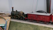
You are using an out of date browser. It may not display this or other websites correctly.
You should upgrade or use an alternative browser.
You should upgrade or use an alternative browser.
Paul Townsend
Active Member
Ta for that but bear in mind the actions were spread over 42 years!
Last edited:
Paul Townsend
Active Member
Here are some piccies of Dartmouth taken over last several years, my record of progress in no particular order.
There are 11 of them with captions so I may spread over several postings.
Future pix will be of more recent work so will appear in my workbench thread "Highbridge and Dartmouth".
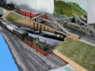
This shows "Olton Bridge" and approaches to the carriage sidings and MPD. This part of the model was entered to Scalefour Society's 1883 challenge at Wakefield Scalefour North in 2014. Derek Russan awarded the Eileens Emporium prize for best scratchbuilt model in the show.
I built the track in foreground but the bridge was built by the late Mike Jolly. I was delighted to be given that by Kay Butler at just the right time to incororate it into the plan for the Dartmouth model.
That prize was my first award since 1980 when the late Guy Williams awarded me "Best track in show " at the Bristol Exhibition for the level crossing at Highbridge !
Here is a view of this trackwork more naked.
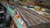
Having built this in transverse sleepered mixed gauge "late BG era", I had to master building baulk road track. This shows the nth attempt!
The fret for a tandem turnout is lasercut in 3mm birch plywood. Simpler frets used 3mm basswood.
Users of the BrookSmith rivetting way of building finescale track may think they recognise what happens next but would be wrong as the bridge rail sits flat onto the baulks. Thus my holes are for 1mm brass pins. The countersunk heads sink into the wood if the right pressure is applied. Any protrusions can be filed flush. The pins on the underside have other jobs to do.........

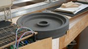
There is MG turntable in the MPD. This well was turned for me by Richard Lane. It is based on a BG TT unearthed at Ladbrook Grove some years ago. Spot the temporary error! The 50ft TT bridge is from a kit by LRM. Top right you can just see the top of the stepper motor linked by timing belt for zero backlash.
There are 11 of them with captions so I may spread over several postings.
Future pix will be of more recent work so will appear in my workbench thread "Highbridge and Dartmouth".

This shows "Olton Bridge" and approaches to the carriage sidings and MPD. This part of the model was entered to Scalefour Society's 1883 challenge at Wakefield Scalefour North in 2014. Derek Russan awarded the Eileens Emporium prize for best scratchbuilt model in the show.
I built the track in foreground but the bridge was built by the late Mike Jolly. I was delighted to be given that by Kay Butler at just the right time to incororate it into the plan for the Dartmouth model.
That prize was my first award since 1980 when the late Guy Williams awarded me "Best track in show " at the Bristol Exhibition for the level crossing at Highbridge !
Here is a view of this trackwork more naked.

Having built this in transverse sleepered mixed gauge "late BG era", I had to master building baulk road track. This shows the nth attempt!
The fret for a tandem turnout is lasercut in 3mm birch plywood. Simpler frets used 3mm basswood.
Users of the BrookSmith rivetting way of building finescale track may think they recognise what happens next but would be wrong as the bridge rail sits flat onto the baulks. Thus my holes are for 1mm brass pins. The countersunk heads sink into the wood if the right pressure is applied. Any protrusions can be filed flush. The pins on the underside have other jobs to do.........


There is MG turntable in the MPD. This well was turned for me by Richard Lane. It is based on a BG TT unearthed at Ladbrook Grove some years ago. Spot the temporary error! The 50ft TT bridge is from a kit by LRM. Top right you can just see the top of the stepper motor linked by timing belt for zero backlash.
Paul Townsend
Active Member
Continuing the Dartmouth retrospective:
It has always been intended as an exhibition layout, exorcising my long felt frustration at not having built Highbridge in the BG era and helping to promote BG modelling and the Broad Gauge Society without whose kits and bits this model would never have been built.
In summertime I do as much modelling as possible in my "Modeller's Paradise" :-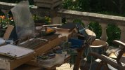
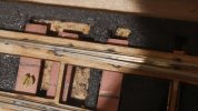
Here you see above a part built switch showing what happens to the pins below the fret.......soldered under the double sided PCB. That anchors the pins and enables electric connections.
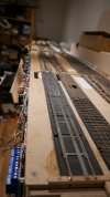
This is a view of the North end of the station. The left track will be in the goods shed.
Below is the overhead LED lighting support rig fabricated from 50 x 50 angle alloy and carried on gallows made with Speeddframe.
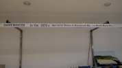
Eventually we all need some sort of control panel. Dartmouth has two mimic panels and here is the MkII version for the rural and traverser areas.
The MKI is for the station and is similar in concept but made too small so it isdestined to be replaced by one similar to the FY panel.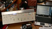
Alongside is the glass panel doing JMRI capers but displaying a MERG setup program for the CBus control system which does everything like turnout servos, signals etc. Track is DCC.
It has always been intended as an exhibition layout, exorcising my long felt frustration at not having built Highbridge in the BG era and helping to promote BG modelling and the Broad Gauge Society without whose kits and bits this model would never have been built.
In summertime I do as much modelling as possible in my "Modeller's Paradise" :-


Here you see above a part built switch showing what happens to the pins below the fret.......soldered under the double sided PCB. That anchors the pins and enables electric connections.

This is a view of the North end of the station. The left track will be in the goods shed.
Below is the overhead LED lighting support rig fabricated from 50 x 50 angle alloy and carried on gallows made with Speeddframe.

Eventually we all need some sort of control panel. Dartmouth has two mimic panels and here is the MkII version for the rural and traverser areas.
The MKI is for the station and is similar in concept but made too small so it isdestined to be replaced by one similar to the FY panel.

Alongside is the glass panel doing JMRI capers but displaying a MERG setup program for the CBus control system which does everything like turnout servos, signals etc. Track is DCC.
Paul Townsend
Active Member
Paul Townsend
Active Member
Here will appear a bunch of piccies introducing Highbridge, after some coffee !
David Waite
Western Thunderer
Hi Paul
Will the Turntable be duel gauge?
David.
Will the Turntable be duel gauge?
David.
Paul Townsend
Active Member
Oh yesHi Paul
Will the Turntable be duel gauge?
David.

Paul Townsend
Active Member
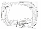
Highbridge track plan showing it with the old room walls. Its in an attachment which is at the end of this post and doesn't show here like the images. Moderators might explain that.
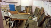
The location was in our Victorian basement from inception in 1980 until we moved house in 2015.
In September 2015 the layout was dismantled for the move into storage until its new home was available in Spring 2016#
Here are a couple of waggons, 2 of dozens provided by No1 assistant Tim.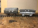
Under the S&DJR Carraige Works and MPD is the throat of GWR fiddle yard. If atrain is in trouble the leds help to see whats up.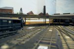
Ages ago on holiday in the South of France we stayed in an ex-level crossing keepers cottage with a shady garden. Mornings involved walking a couple of miles to buy croissants and bread etc, lunch in the bistro followed by an afternoon in the garden, SWMBO would take the sun and read and I settled down to 3 hours modelling before I had to prepare dinner. Three weeks later here is the result: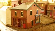
The faultline in the A38 is an artefact of moving house. These scenic baseboards need jiggling a bit to avoid tripping the horses. Did I mentiopn that it is October 1913.
Having settled Highbridge into its new home we finally built the remaining baseboards and laid track for the wharf. Its a bit different from the below track plan as that was intended to enter a little window bay, now not available. The main traffic was cattle out and Baltic and Scandinavian timber in. On the end wall I will build a half relief representation of the large timber mill.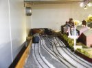
On the right the passenger line to Burnham peels away. All the other tracks are goods only. Lighting has been hugely improved in recent weeks and the wharf is pretty busy now with traffic. In the gloom you can just see a road level crossing, no gates yet. This is the A38 and pre-M5 it was a notorious spot for causing 20 mile tailbacks in both directions on a summer Saturday while the yard and wharf were being shunted!
Here endeth the intro to Highbridge models 43 year history.
The track plan .pdf doesn't show on my screen, I daresay you have to download the .pdf to see it. Moderators explain please.
Future posts will be in my workbench thread "Highbridge and Dartmouth"
The location was in our Victorian basement from inception in 1980 until we moved house in 2015.
In September 2015 the layout was dismantled for the move into storage until its new home was available in Spring 2016#

Here are a couple of waggons, 2 of dozens provided by No1 assistant Tim.

Under the S&DJR Carraige Works and MPD is the throat of GWR fiddle yard. If atrain is in trouble the leds help to see whats up.

Ages ago on holiday in the South of France we stayed in an ex-level crossing keepers cottage with a shady garden. Mornings involved walking a couple of miles to buy croissants and bread etc, lunch in the bistro followed by an afternoon in the garden, SWMBO would take the sun and read and I settled down to 3 hours modelling before I had to prepare dinner. Three weeks later here is the result:

The faultline in the A38 is an artefact of moving house. These scenic baseboards need jiggling a bit to avoid tripping the horses. Did I mentiopn that it is October 1913.
Having settled Highbridge into its new home we finally built the remaining baseboards and laid track for the wharf. Its a bit different from the below track plan as that was intended to enter a little window bay, now not available. The main traffic was cattle out and Baltic and Scandinavian timber in. On the end wall I will build a half relief representation of the large timber mill.

On the right the passenger line to Burnham peels away. All the other tracks are goods only. Lighting has been hugely improved in recent weeks and the wharf is pretty busy now with traffic. In the gloom you can just see a road level crossing, no gates yet. This is the A38 and pre-M5 it was a notorious spot for causing 20 mile tailbacks in both directions on a summer Saturday while the yard and wharf were being shunted!
Here endeth the intro to Highbridge models 43 year history.
The track plan .pdf doesn't show on my screen, I daresay you have to download the .pdf to see it. Moderators explain please.
Future posts will be in my workbench thread "Highbridge and Dartmouth"
Attachments
Last edited:
daifly
Western Thunderer
PaulThe track plan .pdf doesn't show on my screen, I daresay you have to download the .pdf to see it. Moderators explain please.
A .pdf file does exactly what it says on the tin. It is a portable document format file that efficiently carries any kind of content that would be found in a paper document. A .png or .jpg file are the best formats for displaying photos and graphics. I've converted your .pdf to .png to allow it to be displayed on screen.
Dave (not a mod!)
Paul Townsend
Active Member
Thanks Dave.
David Waite
Western Thunderer
Hi Paul
What are the two gauges that you are using? in “mm“
Will you centre the narrow gauge before it reaches the Turntable using “4 rails“ as there seems to be plenty of space between the broad gauge to do so or will you just slip the narrow gauge across on the Turntable?
David.
What are the two gauges that you are using? in “mm“
Will you centre the narrow gauge before it reaches the Turntable using “4 rails“ as there seems to be plenty of space between the broad gauge to do so or will you just slip the narrow gauge across on the Turntable?
David.
Paul Townsend
Active Member
The caption to the turntable picture said " spot the temporary error".Hi Paul
What are the two gauges that you are using? in “mm“
Will you centre the narrow gauge before it reaches the Turntable using “4 rails“ as there seems to be plenty of space between the broad gauge to do so or will you just slip the narrow gauge across on the Turntable?
David.
The track approach in that piccy of 2 years ago is standard Mixed Gauge so can't work for an NG loco.
I have since built the required "stepover" that puts the NG in centre of the BG track. On the far side the two exit roads will be NG only and BG only leading to their respective running sheds.
I have modelled in P4 since 1975-ish so it was natural to follow the BGS recommendation to apply P4 track standards to my MG model rather than the option of EM standards which BGS no longer supports although a few early BG modellers did use that.
Thus my two track gauges are 18.83 mm and 28.0mm.
David Waite
Western Thunderer
Hi Paul
I seen spot the error but couldn’t work out what it was, I seen the track but as it’s a work in progress things get altered so I didn’t count that.
I figured one gauge was P4 but couldn’t work out if it was the smaller of the two or the larger now I know thanks It’s the smaller.
At Peterborough in South Australia the round house Turntable has three gauges 5’3” / 4’81/2” / and 3’6” the narrow Two naturally slip on the Turntable, my wife and I called in there on the way home from the BRMA Convention in SA,
I was last there 37 years ago it’s now a museum not a derelict loco depot like I last seen it it’s well worth visiting if you are ever over there. I look forward to seeing your Turntable construction .
David.
Paul Townsend
Active Member
I now have Richard Lane's permission to identify him as the chum who turned the TT well for me.
Its made of some special MDF type material that is sort of shower proof and warp free. Also comes in thick chunks.
He said it was messy to turn like cast iron for spraying black dust!
Here is the drawing I made from photos and measurements taken at Ladbroke Grove when the early BG TT was unearthed some years ago.
The driving machinery has been proven at "proof of concept stage" but its completion awaits a few roundtuits and completion of higher priority jobs. I will write it up on completion but don't hold your breath. I have a history with TTs and could go on for ever......
Attachments
Martin Shaw
Western Thunderer
The Highbridge part caused an intake of breath, how did I miss this. My maternal grandparents lived in a small village that straddled the A38 about two miles south of Highbridge and in Victorian times there was a generation of 7 siblings all born in the town, one of whom was my mothers great grandparent, can't remember the gender. I haven't been there for 40 years so it's no doubt changed. Some hours were spent on Highbridge's platform in the summer of 65, Western and Warships on the GW and a solitary Ivatt 2 on the S&D. It was a very long time ago.
Martin
Martin

