JimG
Western Thunderer
I have been ploughing on with the track-making over the past two or three weeks - spiking on every tie (sleeper) is certainly not the quickest way to build track. ") I can understand why US layout builders only spiked every fifth tie.
I can understand why US layout builders only spiked every fifth tie.
I've now worked out my way of building the track. Rather than pre-spiking and threading the ties onto the rails, I've reverted to a more normal way of laying.

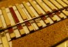
I first lay down key ties at intervals and line them up using the rail fitted in the"slots" on the tieplates and lined up to the Templot plan. These are glued to the track plan with small dabs of white glue. The rail is lightly spiked in three or four places along its length so that it can be moved up to let ties with tieplates fitted slide under it.

Then all the intermediate ties are filled in using the rail pressed into the tieplates' "slots" to align them and small dabs of white glue to hold them to the track plan.

Then all the spikes are inserted to finish the length. That's easy to say, but the above length took an evening to spike. I'm getting better at spiking now but the first lengths of track were taking about two days to do a length of under a yard.
The other important matter to work out was the construction of self-guarding frogs for the turnouts. For those not familiar with these items, they are used in a lot of US rail yards instead of crossings with check rails. Here's a picture of one showing its main features.

The checking is done by the raised edges of the casting bearing on the outside faces of the wheel tyres. It couldn't be used in the UK since our wheels widths vary.

I've finally settled on building the frog using two layers of 1.6mm nickel silver. Here are the two layers with the top on the right and the base in the centre. The two parts will be sweated together to make the unit and the three pegs on the left will be fitted in the end holes to keep them in alignment. I've opted for the pegs since there will be further soldering operations on the frog when rails are fitted and I didn't want any possibility of the layers moving when heat was applied.

The pegs have now been sweated in to the base using my Chinese no-clean solder paste which is still going strong and still usable.

The top is now fitted on the pegs and sweated to the base using the solder paste...

...and the pegs ends are filed flush. I've place a bit of rail to show how the closure rail end of the frog works.

These are the remains of two or more weeks work on these frogs. I started off with the two layers sweated together before machining - at the top - but that didn't work too well and it was a bit wasteful of the nickel silver sheet. I then started cutting the two parts from the sheet, but ran into several problems with tool height which I have now about worked out - I think. One day I went through about forty pounds' worth of small cutters in one hour trying out one method. 

Here are the lengths of completed track laid out in position on the garden station baseboard. The part between the two weights is just the track plan, but the other parts constitute most of the plain track with ties on the layout. The rest of the track is either turnouts, or inset track. And it's not going out there - it's going along one wall of my bedroom.

...and a bit of pipe dreaming. The loco is an S Helper Service SW-1, at the moment DC only but due to get a DCC sound chip in near future. The boxcars are also S Helper Service products.

And back to the tracklaying, with the self-guarding frog placed roughly in position on the turnout timbering. The hole in front of the nose will be used to line it up with the track plan underneath.
Jim.
I can understand why US layout builders only spiked every fifth tie.I've now worked out my way of building the track. Rather than pre-spiking and threading the ties onto the rails, I've reverted to a more normal way of laying.
I first lay down key ties at intervals and line them up using the rail fitted in the"slots" on the tieplates and lined up to the Templot plan. These are glued to the track plan with small dabs of white glue. The rail is lightly spiked in three or four places along its length so that it can be moved up to let ties with tieplates fitted slide under it.
Then all the intermediate ties are filled in using the rail pressed into the tieplates' "slots" to align them and small dabs of white glue to hold them to the track plan.
Then all the spikes are inserted to finish the length. That's easy to say, but the above length took an evening to spike.
I'm getting better at spiking now but the first lengths of track were taking about two days to do a length of under a yard.The other important matter to work out was the construction of self-guarding frogs for the turnouts. For those not familiar with these items, they are used in a lot of US rail yards instead of crossings with check rails. Here's a picture of one showing its main features.
The checking is done by the raised edges of the casting bearing on the outside faces of the wheel tyres. It couldn't be used in the UK since our wheels widths vary.
I've finally settled on building the frog using two layers of 1.6mm nickel silver. Here are the two layers with the top on the right and the base in the centre. The two parts will be sweated together to make the unit and the three pegs on the left will be fitted in the end holes to keep them in alignment. I've opted for the pegs since there will be further soldering operations on the frog when rails are fitted and I didn't want any possibility of the layers moving when heat was applied.
The pegs have now been sweated in to the base using my Chinese no-clean solder paste which is still going strong and still usable.
The top is now fitted on the pegs and sweated to the base using the solder paste...
...and the pegs ends are filed flush. I've place a bit of rail to show how the closure rail end of the frog works.
These are the remains of two or more weeks work on these frogs. I started off with the two layers sweated together before machining - at the top - but that didn't work too well and it was a bit wasteful of the nickel silver sheet. I then started cutting the two parts from the sheet, but ran into several problems with tool height which I have now about worked out - I think.
One day I went through about forty pounds' worth of small cutters in one hour trying out one method. Here are the lengths of completed track laid out in position on the garden station baseboard. The part between the two weights is just the track plan, but the other parts constitute most of the plain track with ties on the layout. The rest of the track is either turnouts, or inset track. And it's not going out there - it's going along one wall of my bedroom.
...and a bit of pipe dreaming.
The loco is an S Helper Service SW-1, at the moment DC only but due to get a DCC sound chip in near future. The boxcars are also S Helper Service products. And back to the tracklaying, with the self-guarding frog placed roughly in position on the turnout timbering. The hole in front of the nose will be used to line it up with the track plan underneath.
Jim.


 .
.)") crossings. The main line retains the standard flangeways but the lighter used line flangeway is raised to the same level as the mainline running rail and is crossed at a speed of 10 mph or less.
crossings. The main line retains the standard flangeways but the lighter used line flangeway is raised to the same level as the mainline running rail and is crossed at a speed of 10 mph or less.


")