Overseer

Western Thunderer
I have done a little more reading (Wikipedia and other online bits and pieces so not definitive) and now think the straight sections of the W1's footplate might be the result of rebuilding following the derailment at Peterborough on 1 September 1955. The earlier photos seem to show a curve to match the A4s while in the the later ones the footplate looks straight ahead of the cylinders. I don't know how much damage the bogie frame did when it fractured or how much was damage resulted from derailing at 20 mph but I imagine there would have been some sheet metal replaced, and without the benefit of a production line to produce the complex shapes near enough would have done. As Mick has pointed out it is only millimetres of difference. But light reflects differently from a flat surface to a curve, even a very shallow curve, so it will look a bit different. Does anyone have photos to prove this hypothesis? I could be completely wrong......
 

Nick Dunhill

Western Thunderer
Mick and I discussed this at length offline the other day. The thing to remember is that as well as a gentle curve along the whole length, the footplate bulges out significantly round the cylinder area (see bottom photo on post 163 above.) The footplate looks straight when viewed from a certain angle as it is the combination of the two curves (longitudinal and lateral) producing this illusion. Interestingly all the shots of the locos where the footplate appears straight are taken from the same angle. It's curved from all others. Mick is right.
 

mickoo

Western Thunderer
Guys, I'll leave it curved, that way of anyone wants to flatten it they can just file it flat, but if I make if flat it's next to impossible to add the 0.2 mm hump if you want it curved ;)

I believe there is no such thing as a straight line, all straight lines are part of a curve at some point, all be it a very 'large' radius, something to do with space, time and gravity :cool:
 
Last edited:

mickoo

Western Thunderer
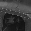
Hard to believe it's not straight between x and y? But at 1:43.5 there's little difference to a flat curve.
View attachment 52619
But full size crop and it's anything but flat ;)


Image1.jpg

What is interesting is that the lower edge of the valance is much flatter so I certainly need to address that and adjust the fillet angles and curves a touch. The flatness/curve perspective also changes whether you have the body on or not or can see the joint between the two, that tends to trick the eye into thinking it's more curved that it really is.

Going back to Overseer's comments regarding post accident, I've some photos with full skirts and in Garter Blue and it looks almost perfectly flat :confused:

Anyway, the metal work will be easily adjustable with a few strokes of a file and easing of the footplate bend to suit everyone's views at the end of the day.

Mick D
 

richard carr

Western Thunderer
Mick

Piercy model products was started by Walter Hodgson, he did the J72, J27 and B1 kits. He started the Q6 kit but he never finished it, I can remember speaking to him several times in the late 90s to find out how he was getting on with it but it was always the same answer of its nearly finished another 6 months and it should be ready.
When he passed away DJH took over the range and fairly quickly brought out the Q6, followed by the others.
I am told, and of course it could be complete rubbish, that the pattern for the A4 body was supplied by Tony Reynolds, much to Martin Finney's annoyance, as allegedly, it is the same one or has the same origins as the one that Martin used.

The B1 kit seems to have disappeared completely from the range and the Footballer is now only available ready to run.

The W1 is looking great.

Richard
 

mickoo

Western Thunderer
The B1 kit seems to have disappeared completely from the range and the Footballer is now only available ready to run.

The W1 is looking great.

Richard

Richard, strangely I have a photo shoot on a B1 planned for Monday ;)

Footballers are nice looking engines too but I keep looking at some of these larger LNER and NER freight engines on and off.

W1, cheers, it's getting there, more issues with the cab roof and angles etc, despite planning and drawing in CAD to great accuracy the curves and angles of the V front are just not quite right, so I'm working through those ready for the Mk II etch :thumbs:

Interesting information on the Piercy range and from recollection the Finney A4 body does have a close semblence to the Hachette shell I have :cool: which I believe is close to and maybe identical to the Piercy one. I'll be able to cross reference the Finney and Hachette after the weekend a bit better.

Mick D
 

mickoo

Western Thunderer
Moving onward, I have graciously been lent a Finney A4 body, suffice to say it is a perfect fit, almost ;).... just a trim here and there to make the fit perfect.

IMG_5635.jpg

The footplate is too wide by 0.4 mm so needs further trimming on the artwork so that the valance blends with the buffer casing neatly.

Image2.jpg

The boiler and smokebox casing is also perfect length wise, the DJH one is a little out at the front, when you line the lubricator opening up with the footplate there is a resultant gap at the front of about 1.2mm, I'll simply extend the foortplate, valance and valance support plate. In fairness the Hachette one is also correct for boiler and smokebox length.

IMG_5638.jpg

Checking the cab V shows an exact match, but then it also matches the DJH and Hachette, so they're all correct in that respect.

Image1.jpg

Mick D
 

mickoo

Western Thunderer
Time for a little update, things have been rolling along in the back ground, lots of little fiddly bits taking a lot of time.

Moving down below I needed to work out how the ash pan folds up to give an accurate rendition with foundation ring etc.

Drawing in Autocad, printing out and sticking to spare scrap allows one to work out if it's actually all going to work, given the angles and bends it took a while, and whilst hand cut will work once translated to the art work, even so I may just throw this onto a small test piece before committing to adding it to a larger sheet. Four trial pieces later we arrive here.

IMG_6370.jpg

and fitted in the frames, there are some gaps but these close up when all held together ready for soldering, it's the fold up shape we're primarily interested in here.

IMG_6371.jpg

The ash pan will be in two parts, an upper and a lower, simply because working out this part was hard enough, without adding the bottom shape and folds too, besides adding the bottom to the current shape isn't possible so a joint would be necessary anyway.

The upper part is attached to the footplate, the lower part will be attached to the chassis, the upper part is slightly narrower that the lower part so will fit inside the lower part, the joint being naturally hidden by the inner frame extensions. The split will allow all the dampers and linkages to be modeled and fixed to the chassis in the correct places without having to work out how to extract it all if the ashpan were one part.

At the rear you can see the cut out for the rear foundation ring support attached to the main frames, the ash pan will continue past the outside of this and close off the small gap to the rear, I simply damaged this bit when I dropped the part, rather than leave it a mess and try to straighten, I cut it off and binned it.

Side profile.

IMG_6372.jpg

I haven't for obvious reasons cut the mud hole door and wash out plug openings, nor the grate rod hole, but they will be present on the etched version.

Placing the cab on shows how low the front end was to fit the DJH shell so Mk II cab will have a new higher cab front to suit the correct Finney shell.

I've also been trial fitting a test piece for the firebox. I wasn't sure of the exact length I needed so made is smaller on purpose, it was the fit at the front end that was important, the length I could resolve later.

IMG_6364.jpg

IMG_6365.jpg

The test piece was worked up to make sure it fitted and the complex shape at the front fitted the cab V with minimal gaps.

IMG_6366.jpg

Back head now in the right position, now it's simply a case of measuring the gap, fabricating a new test piece and folding it up to make sure it all fits, and then translating that shape to the art work. comparing the back head position to the side windows with the GA's shows the position to be perfect.

Mick D
 

mickoo

Western Thunderer
Steph, pretty big at 50 Sq feet, I think only the Garratt U1 at 56.5 was bigger.

The firebox and boiler design was based on the P2/3 with only materials being the major differences.

Mick D
 

Overseer

Western Thunderer
Is the W1 going to be the first new release from Finney7? Would seem to be a sensible use of existing components from the range even though it was a one off. Watching the development of the etched parts has made me want to build one even though I have absolutely no need for one nor even a real interest in the LNER streamliners. It would have to be S7 though.:)
 

mickoo

Western Thunderer
Is the W1 going to be the first new release from Finney7? Would seem to be a sensible use of existing components from the range even though it was a one off. Watching the development of the etched parts has made me want to build one even though I have absolutely no need for one nor even a real interest in the LNER streamliners. It would have to be S7 though.:)
Interesting proposition, there's a lot in common between the W1 and A4 classes.

The original concept was for finescale, all be it with much tighter tolerances, the frames are 28.00 mm over rivets, question is, what's the accepted width over S7 frames, that's the million dollar question, I model 30.00 mm but I've heard others prefer 29.00 mm or possibly narrower.

The problem with the W1 is the complexity of all the stays, last count 36 individual parts, the question has been asked before ;). It's not impossible but a wider duplicate set takes a lot of space on the etch and it wasn't laid out for dual gauge building, the next engine after the W1 will of course, unless 28,00 mm over rivets is acceptable for S7 frames.

The Finney A4 stretchers give a frame width of around 28.50 mm out of the box, later kits push that a little higher.

Mick D
 

Eastsidepilot

Western Thunderer
I model 30.00 mm but I've heard others prefer 29.00 mm or possibly narrower..............

...............unless 28,00 mm over rivets is acceptable for S7 frames.

The Finney A4 stretchers give a frame width of around 28.50 mm out of the box, later kits push that a little higher.

Mick D

Most if not all the S7 loco's I've built have had 29mm o/a frames. This seems to be an acceptable dimension to most, it does give some side play clearance for those running on tighter curves etc. and bogie wheel clearances can be a problem which this helps with , so I reckon 28.5 - 30.oomm for o/a S7 frames is ok.:thumbs:

Col.
 

mickoo

Western Thunderer
Most if not all the S7 loco's I've built have had 29mm o/a frames. This seems to be an acceptable dimension to most, it does give some side play clearance for those running on tighter curves etc. and bogie wheel clearances can be a problem which this helps with , so I reckon 28.5 - 30.oomm for o/a S7 frames is ok.:thumbs:

Col.
Colin, that does seem to confirm what I've heard whispered here and there.

Because the W1 has an etched outer overlay the width over plate work is only 27.50 mm, but over rivets is nearer 28.00 mm and it'll be those raised details that touch the wheel rims first and short it out.

For finescale 28.00 mm is quite wide, the Finney A4 has something like 25.85 mm over frames for finescale (measured spacers off the etch without cusp removal) and 27.95 mm for S7. Both quite narrow in my view.

I did drop in some S7 wheels at the rear end as a comparison.
IMG_6387.jpg

Tolerances have got tighter over the years so you could use the A4 S7 spacers for a finescale model if you wanted close tolerances, clearly the days of 26.00 mm for finescale receeding.

So, the question is, are a set of frames set to 28.00 mm acceptable for both gauges ? For me personally it's not, I much prefer as near to 30.00 mm as possible and yes it does limit the curvature. However given the additional cost (below) it would take to add S7 stretchers, I think I'd live with it.

Going back to the Finney A4, there are only three or four spacers I think, not a lot of art work or space taken up offering both for users, on the W1 the stretchers and stays take up nearly 40% of an A3 sheet of etch, so that brings another question, do you offer both sets in one package, bearing in mind that for every single model, 40% of the chassis etch is waste, and that 40% adds 40% to the material costs.

Should those modeling (assuming for theory purposes that this is a commercial commodity) finescale or S7 have to pay the extra 40% on the chassis for the waste they are never going to use, the parts are totally incompatible?
I'd say not, so, do you run with finescale only and cut off S7, or, offer S7 as well but as an extra...but then why should S7 modelers have to pay more for those parts, surely they are entitled to the same pricing as finescale modelers.

Trust me, the issue of S7 and/or finescale has vexed me for some considerable time, the problem is, the more complex we modelers make the frames...and I strongly believe this is the way forward.....the bigger this issue and resultant cost becomes. In the days of tube spacers and simple L or U spacers the issue was virtually zero, but when your talking nearly 50 individual parts that make up 40% of the metal work and 75% of the construction parts, then it's a different ball game.

Ironically, the rear end where the frames widen is true scale, thus giving me the maximum space for the rear bogie and Cartazzi truck to swing when using finescale wheels, the front end is a different matter and some cunning and limited side play will need to come into force to stop the rear bogie wheel touching the cylinder wrappers.

Either way, the W1 is not designed to be run on four foot curves laid on the carpet ;) there are plenty of models already out there for that. It should cope with 6 foot radius but I think 7 foot is more comfortable, even then, for an engine this big, 7 foot is realistically very tight. If it runs round something like Heyside then it'll achieve what we set out to achieve at the start of the project. The test chassis did run through Love Lane crossover with no problems so it should all work fine.

Mick D
 

Ian@StEnochs

Western Thunderer
Mick,
Could the spacers be supplied to S7 dimensions but with 1/2 etched markings for fine standard 0 modellers to trim back to? Anyone tackling a big loco like this will not be beginners and thus the trimming will be well within their comfort zone. In fact it would just be an extension of the normal fettling required on thicker frames material.

Ian.
 

Eastsidepilot

Western Thunderer
Mick,
Could the spacers be supplied to S7 dimensions but with 1/2 etched markings for fine standard 0 modellers to trim back to? Anyone tackling a big loco like this will not be beginners and thus the trimming will be well within their comfort zone. In fact it would just be an extension of the normal fettling required on thicker frames material.

Ian.
Just what I was going to say Ian:).......as for tight radii Mick do you know what the min. radius was for this loco
The cross overs on Love Lane are B7's if I remember, that's 6 3/4 chains.

Col.
 

mickoo

Western Thunderer
Ian, Colin,

Fair point and worth considering, however if I was present with a model that require 75% of the chassis to be modified to work in fine scale (which is where the majority of modelers actually lie) I'd be a tad miffed ;)

Your effectively making the majority of modelers suffer for the minority interest group. I think you'd be setting yourself up for some severe criticism by forcing fine scale modelers to have to hack things about to make it work.

Many of the stretcher parts have tabs to slot into the frames, so it's not all one single cut to reduce the width, you have to cut in and out to maintain the tabs, other parts are fold up, adding extra fold up lines reduces the strength and leaves unsightly half etch lines in the parts. Some parts have lightening holes which follow the parts outline, reducing the outline would require reducing the holes to match or else it'd look odd with webbing and fillets in odd sizes.

Minimum radius, not sure Colin, I'll see if RCTS lists it, possibly not.

Mick D
 
Top