Marchford Creek

Bullhead

Western Thunderer
By my standards, I’ve made quite a bit of progress with wiring this week. The DCC distribution system is complete. The un-coupler electromagnets have been connected to their control board, which now looks a lot neater. All the point motor wiring has been routed and tidied up with spiral wrap. Next on the agenda is to complete the IR train detection system for the traverser.
upload_2019-2-21_22-39-25.png

upload_2019-2-21_22-40-8.png

upload_2019-2-21_22-40-47.png
 

Bullhead

Western Thunderer
My plan for this weekend was to construct the IR train detection equipment but on gathering the components and reminding myself how it all went together, the realisation struck that I had bought two different types of IR receivers and no transmitters. A quick order placed will remedy that by Monday but a different project was needed.

I turned my attention to the layout lighting. Some time ago, having read up on the subject from various sources, I bought some led strips in warm and cool white to enable a suitable mix to be formulated for my daylight setting. Three long and two short strips seemed a good way to start to suit the layout’s geometry and I opted for three in warm and two in cool for the first trial in colour balance.

This worked well for colour but needed a little adjustment in position to give the best overall effect. Having got everything set up it seemed a good idea to position all the buildings and have a photo session to test the overall appearance, colour balance and shadows. All these pictures were taken on my phone using just the layout led lighting. Hope you like the results.

upload_2019-2-25_17-2-53.png

The arrangement of led strips. For test purposes, these have just been positioned with masking tape. The inside of the “lid” has been given a coat of white paint to help to reflect light.

upload_2019-2-25_17-3-23.png

The layout box with lights on. The yellow glow at the top seems to be a camera effect and is not visible to the (my!) naked eye. The electrical panels have been positioned for effect. Note removal of the traverser winder to facilitate forthcoming painting of the front facia. Having a new deadline, I may even be able to do the planned upgrade to electric motor operation!

upload_2019-2-25_17-3-59.png


upload_2019-2-25_17-4-49.png

upload_2019-2-25_17-4-26.png

upload_2019-2-25_17-5-18.png

upload_2019-2-25_17-5-37.png


upload_2019-2-25_17-6-29.png

upload_2019-2-25_17-6-48.png

upload_2019-2-25_17-6-58.png


upload_2019-2-25_17-7-20.png

Driver’s eye view coming off the traverser.

upload_2019-2-25_17-7-50.png

His day’s work done, Jim sits under his shelter. Looking out through his sad rectangular eyes, he wonders if the Marchford Creek scenic department will ever arrive!
 

Attachments

  • upload_2019-2-25_17-6-16.png
    upload_2019-2-25_17-6-16.png
    370.3 KB · Views: 208

Bullhead

Western Thunderer
Hello All,

It has been far too long since my last post. I’m still here, pressing on with Marchford Creek as fast as spare time allows.

The final control PCB has been completed. This one is the receiver board for the infra-red train detection system and will operate the track occupation indicators for the traverser. Again, this uses surface-mount components on a home-etched pcb. I will post more on this part of the system soon.

upload_2019-5-3_13-22-54.png


The layout lid and front facia have been given a coat of primer and I have sourced a rather restful shade of sage-ish green that will be used to finish them off.
upload_2019-5-3_13-23-12.png

In odd moments here and there, I have been testing the track and doing a few tweaks on some rough spots and a couple of places where the flangeways were a bit tight.

upload_2019-5-3_13-23-36.png


Testing showed that one of the wing rails in the slip needed improvement to get the geometry spot on and to open out the flangeway to the correct clearance. Having completed the replacement, running is much smoother. There are still a few uneven rail joints needing attention and a good number of dislodged cosmetic chairs to be replaced (again!). I remind myself that that some additional time invested now will save loads of trouble in the future!

One thing I have been able to do recently is some reading. Specifically, I have revisited some of the material on the Scalefour Society website (particularly the extremely useful and comprehensive contribution by Will Lichfield) about springing vs compensation for rolling stock. The general opinion expressed seems to be that springing gives far superior running compared with compensation. Further, CSB (continuous springy beam) suspension appears to offer a construction method that is no more difficult to achieve than beam compensation. In addition, it looks like a straightforward option to make wheelsets removable, retained securely by the suspension beam itself. This appeals to me as it means wheelsets can be set to gauge and quarter away from the chassis. I would be interested in any thoughts or feedback on this subject from those with experience of the techniques.

Another topic that I’ve been researching and experimenting with is loco pickups. Whilst looking at suspension, I came across a pickup design in Will Lichfield’s material that jumped out at me. Will uses a hard brass wire support (0.7mm) with a springy pickup wire fabricated from phosphor-bronze or similar mounted on it. I have used 0.25mm beryllium copper for my prototype springs. The big advantage of this method is that the length of unsupported pickup wire is reduced as the coil spring section is reinforced by the 0.7mm brass core. The next challenge is to figure out the best way to configure a sub assembly for attachment to a completed chassis.
upload_2019-5-3_13-24-4.png
 

Bullhead

Western Thunderer
Some recent progress or two steps forward and one back.

The infra-red emitters have been mounted on gantries above the traverser, one to show track occupation and the other to indicate over-run.

upload_2019-5-24_20-52-30.png


The gantries were soldered up from brass strip and are bolted to the parapet walls of the traverser. In order to give the widest possible effect, the track occupation unit is mounted at 45°.

upload_2019-5-24_20-53-1.png


The receivers are mounted in the corresponding positions between the rails. The holes are quite deep which should help to prevent triggering by any stray light. The electronic design for the unit came from here http://www.ho-ptit-train.be/html_en/cablage_04_en.html

upload_2019-5-24_20-53-25.png


upload_2019-5-24_20-54-16.png


upload_2019-5-24_20-54-33.png


My frequent vague allusions to “possible motorisation of the traverser at some future time” have moved closer to reality with the sourcing of this little gem.

upload_2019-5-24_20-54-50.png


It’s a 6v motor with 298:1 gearing obtained for just a fiver from Pimoroni. Slightly inconvenient that it needs a 6v power supply but that is easy enough to rig up. Initially, I had considered letting the motor stall at each end of its travel as the stall current is low. However, the amount of torque it produces is phenomenal for its size so an end-stop microswitch will be used at each end to cut the motor current. A two-pole centre off dpdt switch will reverse the motor supply and a push-button switch defeats the end stop microswitches to start the thing moving.

upload_2019-5-24_20-55-20.png


Here is the motor duly installed in a bracket fashioned from some aluminium u channel. The coupling to the motor is a piece of 4mm id polyurethane tube which is a tight fit and is further restrained using cable ties. The whole assembly works ok but is excessively noisy. A number of modifications are under consideration to cure this.....

upload_2019-5-24_20-55-50.png
 

Attachments

  • upload_2019-5-24_20-50-4.png
    upload_2019-5-24_20-50-4.png
    301.6 KB · Views: 193
  • upload_2019-5-24_20-50-25.png
    upload_2019-5-24_20-50-25.png
    249.9 KB · Views: 185
  • upload_2019-5-24_20-51-27.png
    upload_2019-5-24_20-51-27.png
    229.8 KB · Views: 198

Bullhead

Western Thunderer
Hello All,

Things have been a bit slow at Marchford Creek over the summer months as there have been lots of other things to do. I have made some significant progress though and thought it was time for an update.

The most obvious sign of progress is the painting of the exterior cabinet surfaces. The inside of the lid and the backscene panels are now primed and ready for scenics to be applied.
upload_2019-9-4_13-43-8.png


I attempted to fit a self-adhesive photographic backscene but ended up with more creases than I could shake a stick at! This, I should stress, was entirely down to my own ineptitude and impatience, not the quality of the product. Having reconsidered the possibilities and viewed some how-to videos, I’ve decided to have a go at painting the backscene myself. A few practice sessions have given me some confidence that this could work. More on this to follow.

The daylight lighting led strips have been permanently fixed into position in the lid. An additional blinder was added to prevent direct visibility of the lighting strips from normal viewing angles.
upload_2019-9-4_13-51-34.png

A separate night-time light bar was made up on a 500mm strip of copper-clad circuit board using 2x cool white and 3x blue smd leds. This bar is mounted on the inside of the front facia and gives a nice moonlight effect to the scene. The two different levels of light are selected from a front panel switch.
upload_2019-9-4_13-50-1.png


upload_2019-9-4_13-44-15.png


upload_2019-9-4_13-44-30.png

The rather inadequate traverser motor previously installed has been replaced with something a bit beefier. A motor mount incorporating two layers of rubber sheet was contrived in order to minimise noise transmission. The flexible coupling to the shaft is a piece of tight-fitting polyurethane tubing.
upload_2019-9-4_13-45-5.png

Wiring is officially complete! Everything is connected to something else and it all works as designed after a bit of tweaking and the correction of a few mistakes. The main control panel has switches for the Tortoise point motors. Led position indicators for the points are driven by one of the switches built into the motors while the other looks after frog polarity. Uncoupler magnets are powered from biased switches so that each switch operates one electromagnet in each direction. The spare contacts on each DPDT switch are used for the led indicators on the panel. The position indicators for the traverser are simply connected to microswitches operated by the movement of the table. Switches at each end must close in order for the positive indication to be given. Finally, the infra- red system for indicating track occupation on the traverser works very well and I'll post separately on this in the near future.
upload_2019-9-4_13-46-17.png


upload_2019-9-4_13-46-44.png


The next phase will be a period of intensive testing of track and electrics with the aim of flushing out any gremlins before scenic work (finally!) begins. Should be fun!
 

Attachments

  • upload_2019-9-4_13-43-44.png
    upload_2019-9-4_13-43-44.png
    235.1 KB · Views: 176

Bullhead

Western Thunderer
As promised, some more detail about the traverser monitoring system on Marchford Creek.

The idea of this system is to give the operator at the front of the layout a positive indication that the traverser deck is correctly aligned with the exit track and a reminder of where stock is berthed, without the need to look ‘round the back’.

Traverser deck position as previously mentioned, is simply taken care of by two microswitches at each end of travel. Once both switches close, the relevant panel led lights to confirm position. Simple screw adjusters allow for fine tuning of the position at which the switches operate.

The traverser mechanism operates via a push to make switch and a DPDT centre off switch. At each end of its travel, a microswitch cuts the power to the motor. For the return journey, the direction of travel is selected with the DPDT switch, the pushbutton then overrides the power off microswitch to get things moving. Once the microswitch has closed, the unit continues on its way until the other side is reached and the second microswitch cuts out.
upload_2019-9-12_13-8-15.png

In order to give an indication of track occupation on the traverser, an infra-red (IR) system has been adopted. This uses the principle that an item of rolling stock positioned between an IR emitter and receiver causes a panel led to illuminate. I found a suitable design published online here http://www.ho-ptit-train.be/html_en/cablage_04_en.html
The four independent IR units are mounted on a single pcb as previously described. This and the mounting arrangements for the transmitters and receivers have been described earlier. Each traverser road has two detector units, one angled to give the maximum possible coverage along the length of the track and the other positioned at the end to give an operator warning of an impending collision with the end stop. The IR units proved to be easy to make and are very reliable in operation.

The following pictures illustrate the control panel indications (top left corner) for different distributions of stock. The green light indicates correct track alignment, yellow shows track occupation and red warns of imminent collision with the end stop!

upload_2019-9-12_13-8-52.png
upload_2019-9-12_13-9-12.png


upload_2019-9-12_13-10-46.png

upload_2019-9-12_13-11-3.png


upload_2019-9-12_13-11-19.png

upload_2019-9-12_13-11-46.png
 

Bullhead

Western Thunderer
Hello All,
Once again, modelling time has proved elusive in the last few weeks. I have managed to complete testing on the electrics and sorted out a couple of mistakes in the wiring. Next step was to try to get something moving. After some track cleaning I retrieved my 48DS from the drawer and did a good clean on the wheels and pickups. Here is a short video of the results.


A few tweaks are required here and there but generally, I'm very pleased with the running achieved.
 
Last edited:

Bullhead

Western Thunderer
During the recent cleaning and testing frenzy at Marchford Creek, there were a few issues identified. Two turnouts required a slight tweak to increase clearance of the switch blades and one check rail was dislodged by overzealous cleaning (it was weak due to poor soldering in the original construction). All these have been set to rights and my attention has turned (at last!) to scenic work.
upload_2019-11-12_12-25-53.png


The beginnings of a backscene have been applied to the interior of the layout lid using a tester pot from Wickes of a shade appropriately named “sky”. This has given a good base to work on, the colour being somewhat misty/grey in hue. This, I think is desirable as there is no intention to draw the eye to the backscene, rather, to frame the foreground in an eye-pleasing way without clashing or diverting attention from the main attraction.
upload_2019-11-12_12-26-16.png


Meanwhile, on a nearby sheet of MDF, some techniques for backscene painting have been tried out. It’s very much a work in progress but the early results are encouraging. The whole board was painted in the aforementioned sky colour with a brownish colour (name forgotten), from the same source, added to define the land shape. Clouds and details were then over-painted using artists acrylics.
upload_2019-11-12_12-26-39.png
 

Pushpull33

Western Thunderer
Wow, I've been following you all the way through this build, you are coming out with some neat ideas. An awful lot of thought has gone into this, something that can inspire us all. Keep up the good work and will eagerly await the next post.
Colin
 

Bullhead

Western Thunderer
Hi Colin,
Thanks for your kind comments. There is a bit of momentum building so hopefully more updates soon.
Cheers,
Peter
 

Bullhead

Western Thunderer
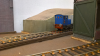
Scenic work is gaining momentum. The backscene has had some definition of horizons added and coloured with artists acrylics to give a vague impression of vegetation receding towards the far horizon. Detail may be added to this as the build progresses, depending how everything looks together.

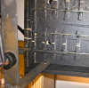
Over the last week or two, scenic treatment has begun in earnest starting at the western end of the site. The first task has been to lay the cobbled yard surface around the ‘new’ shed. This was done using Wills sheets which have a very good surface texture and a believable irregularity. Early experiments with this material gave encouraging results and a painting scheme was developed that looked acceptable.

The first stage was to build up the ground level to match the height of the sleepers. Grey board of suitable thickness was used for this purpose, cut to fit and fixed with PVA.
upload_2019-12-11_16-11-30.png


Next, the rail sides and the gap between check rails and running rails was painted with a mix of matt black and sleeper grime.
upload_2019-12-11_16-11-43.png


The plastic sheets themselves were marked out using marker pen ink applied to the rail tops to transfer onto the underside of the sheets as a cutting guide. This worked well and close-fitting sections were achieved with minimal fettling. The sheets are quite thick, so care, patience and a sturdy blade are required.
upload_2019-12-11_16-11-56.png


Once the sheets had been cut and fettled to a good fit, they were stuck in place. Some work was done where the edges sit against rails to ensure that the rail head is proud of the surface so that rail cleaning will not cause damage to the finish. This meant slightly thinning the edges and removing some material from below to ensure a neat fit.
upload_2019-12-11_16-12-22.png


A quick check with the building in place to make sure everything fits correctly.
upload_2019-12-11_16-12-40.png


Due to the size of the sheets, joins were unavoidable. A little filler was used to disguise any small gaps.
This filler has become my favourite. Apparently, it’s good for decorating too!
upload_2019-12-11_16-13-0.png
 

Bullhead

Western Thunderer
Two months since my last entry and I have to acknowledge that not as much progress as I would like has been made on the layout in that time, while I have been enjoying other pursuits.

Since last time, the cobbled area at the western end of the system has been painted. This was a long-winded task involving a series of processes based on experiments previously conducted on my test panel. First, the whole area was painted in matt black. Then successively lighter shades of grey were dry brushed over the surface to accentuate the relief and give variation in the colour of the stones. Once satisfied with the appearance of this, a final dry brushing with a mix of light grey and Humbrol MetalCote gunmetal was judiciously applied and burnished lightly to give a sheen. Finally, a dirty wash of sleeper grime was applied to bring it all together.

Next job was to form the ground levels between the tracks. This was achieved using a base layer of laminated foamboard, carved at the edges to the required profile. Once the rough profiles were in place, the surface finish was built up using thin layers of fine surface filler. Repeated filling and rubbing down with wet and dry paper resulted in a pleasing smooth finish. Once complete, the whole area was painted with two coats of sleeper grime diluted 50:50 in white spirit to maximise penetration into the filler.

Some work has been done on forming the concrete pad area using foam sheets from Hobbycraft. I’m not 100% happy with this yet so more to do here.

The next task is to replace all the cosmetic chairs that have become dislodged and then paint the track.

upload_2020-2-13_20-3-22.png
upload_2020-2-13_20-3-41.png

A before and after to show the painting of the cobbles

upload_2020-2-13_20-4-5.png


Early stages of adding the ground fill between the tracks.

upload_2020-2-13_20-4-27.png


Ground fill complete and ready for paint

upload_2020-2-13_20-5-6.png

upload_2020-2-13_20-5-29.png


After painting

upload_2020-2-13_20-5-55.png


Forming the infill for the concrete apron
 

Bullhead

Western Thunderer
Hello All,

Despite my initial fears about tackling scenic work, I’ve started to enjoy myself and the results are looking pretty much as I’d hoped.

Following on from last time, all the missing cosmetic chairs have been replaced and the track given a first coat of thinned sleeper grime to get things started.

After a great deal of time and internal debate, the “concrete” surface in the yard has been laid…

upload_2020-3-19_13-31-47.png


…and painted with successive washes of grey and concrete shades….

upload_2020-3-19_13-31-59.png


….followed by a brown wash and some weathering powders to vary the tone and emphasise the area between the rails where oil, ash and soot deposits from locos have stained the surface.

upload_2020-3-19_13-32-11.png


I’ve also started on a crane platform for the centre section of the yard. This is a completely freelance structure combining brick and timber sections. The fiction suggests that the brick end was modified at the time the concrete extension to the yard area was added. It is constructed from embossed plastic brick sheet, ply sleeper strips and mounting card.

upload_2020-3-19_13-32-34.png
upload_2020-3-19_13-32-41.png


A detail I have long been pondering is control of the turnout connecting the “main line” with the yard. In the past the line was operated as a goods only branch so my thoughts were to install a ground frame that would control the junction, unlocked by a train staff or other device carried by the train crew. In most circumstances, this arrangement would incorporate a facing point lock. As the line is goods only, is a FPL appropriate? Given that many of the materials carried into and out of the yard are highly flammable and/or explosive perhaps such a safety device would be justified! Any comments or guidance on this subject would be greatly appreciated. The components pictured are from the excellent Wills Ground frame and point rodding kit.

upload_2020-3-19_13-32-52.png


Next steps are to finish painting the track, provide texture and colour to the other yard areas and complete the crane platform.
 

AJC

Western Thunderer
A detail I have long been pondering is control of the turnout connecting the “main line” with the yard. In the past the line was operated as a goods only branch so my thoughts were to install a ground frame that would control the junction, unlocked by a train staff or other device carried by the train crew. In most circumstances, this arrangement would incorporate a facing point lock. As the line is goods only, is a FPL appropriate? Given that many of the materials carried into and out of the yard are highly flammable and/or explosive perhaps such a safety device would be justified! Any comments or guidance on this subject would be greatly appreciated. The components pictured are from the excellent Wills Ground frame and point rodding kit.

View attachment 119677

I like that a lot - though the Will's rodding is roughly 7mm scale - the colouring and overall effect is superb thus far. Can't wait to see more!

Adam
 

Bullhead

Western Thunderer
I like that a lot - though the Will's rodding is roughly 7mm scale - the colouring and overall effect is superb thus far. Can't wait to see more!

Adam
Thanks Adam.
You are right about the rodding, it is a bit chunky. Fortunately it's not a massive issue as there is only going to be a very short run.
Cheers
Peter
 

Bullhead

Western Thunderer
Hello All,

Track painting is the current priority. It is a bit of a boring task and I’m having to tackle it in small doses when time is available in order to keep up a reasonable standard of work.

The first question is one of colour; a tricky subject as it is so subjective and there is a great deal of variation in the prototype. To cut a long story short, I looked at loads of pictures and then set to work with paints to experiment. After much debate, my chosen scheme is

1. A diluted wash with sleeper grime all over (as seen in the previous post).

2. Rust colour applied to rail sides and dry brushed onto chairs.

3. A diluted coat of brake dust applied as 2.

4. Another sleeper grime wash to tone it down and bring everything together.

All the paints selected are enamels. I find them easier to use than acrylics and the matt finish they give has a nice dusty look even when well thinned. The rust shade selected was this one from Humbrol. It has been in my collection for many years but has kept really well.

upload_2020-4-14_21-32-21.png
upload_2020-4-14_21-32-29.png


On its own it looks a bit garish but when the other colours are added it all blends together nicely. I’m sure I could have found a one coat mix to do a similar job and save some time, but the staged approach does provide some subtle variation in tone across the whole piece. Brake dust and sleeper grime are from Railmatch.

upload_2020-4-14_21-33-13.png


This shows stage 3 in the foreground with stage 2 behind.

upload_2020-4-14_21-33-29.png


To break up the monotony of track painting, I have been working on a Rumney models sprung wagon underframe. It is massively enjoyable to work on this well designed and beautifully etched kit – a real test of eyesight, manipulation and soldering of some extremely small components. By carefully sticking to the instructions it is going together very well so far.

upload_2020-4-14_21-34-4.png


upload_2020-4-14_21-34-20.png
 
Top