Nice idea Jim,

a winch very clever

Well, I used the winch again and got a couple of the boards down to start work on the layout again - at last.
All the other tasks and deadlines I was mixed up in have passed and I can now looking at doing my own S scale modelling again.
Following on from my last message I've decided to work on the boards singly or in pairs, and downstairs in the kitchen where I can work reasonably well and the floor cleans up quickly.
I decided to start on the board with the double junction on it - that's the double junction that's in full view - the other being in the hidden sidings. A quick look at the trackwork reminded me that I still had a lot to do on it. The radii through the diamond are very tight for S scale - around 42" radius - with maximum gauge widening through them, so getting the crossing to work has been a real fiddle and the present diamond is the second attempt. I remember deciding that the best way to proceed was to be able to test the diamond by running locos and stock through it under their own power and that was the reason for originally setting the boards up in situ and trying to get all the track down and get something running. I will still do the testing with locos and stock, but with one or two boards hooked together and shuffling them back and forth.
Here's the picture of the board in question in the kitchen

The interlaced sleepering through the diamond was copied from a Caledonian drawing and the wide pitch of some of the sleepers is as in that drawing.
The first thing to do was wire up the board so that I can run a loco. The layout will be DCC controlled but will have a fall-back provision for DC working in case there are any problems. I intend to split the layout into four power districts - the inner and outer main lines, the goods yard and the hidden sidings. The fall back DC working will be using the power districts as sections to give a very basic cab control with four sections.
I started putting droppers in from all the running rails, using 1.5mm cable stripped from the coil of twin and earth on the board. The dropper is soldered to the underside of the rail and will be almost invisible when everything is ballasted.
Underneath I'm using 2.5mm cable as the power busses - again stripped from 2.5mm twin and earth. My wiring is a bit experimental since I'm aware of warnings of possible interference between feeds in DCC circuitry so I'm trying to keep things as widely spaced as I can.

There are the two bus pairs here for the inner and the outer circuits. The ends in the bottom right corner will go to a tag board from which will go links to the socket for the interconnecting cables. The joints between droppers and bus wires are pretty basic but strong - one wrap round of the 1.5mm wire and soldered. However they can be unsoldered and split quite easily if necessary.
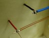
The bus wires are cable tied to the baseboard framework to cut down movement.
The next job will be to wire up the crossings and the obtuse crossings of the diamond so that I can jury rig power feeds to allow a loco to work the crossing.
The intention is to use MERG CANBUS units to control the pointwork and signals on the layout, with the pointwork and signals being worked by small servos. One MERG unit will control the two turnouts and one signal on this board as well as the relays to switch the feeds to the crossings.
Jim.


 Do you have an assistant or can you manage it on your own?