You are using an out of date browser. It may not display this or other websites correctly.
You should upgrade or use an alternative browser.
You should upgrade or use an alternative browser.
A speeder - finescale of a sort!
- Thread starter Peter Insole
- Start date
Tom Insole
Western Thunderer
Gosh and golly! They are big boys. I assume as they have grease nipples pressing the races out isn't going to work. Steel bodies like that would take a lot of fettling to make smaller blocks too.
By 'eck. What a conundrum.
Tom.
By 'eck. What a conundrum.
Tom.
cmax
Western Thunderer
Unfortunately, the items were supposed to be dispatched at "Large letter" rate - and as no one has owned up to the missing consignment, despite the vendor being a so-called "premium" seller, (they refused to reply to any of our queries) I do rather suspect that it was more likely that the items were not even posted in the first place. (?) Whatever had gone wrong, the "famous trading site" took it upon themselves to refund me today, so a new set of bearings were ordered, this time from another source - and where the goods can also be tracked!
Meanwhile, I have been quietly suffocating in our little corner of the Suffolk sauna, while desperately trying to stay awake and at the same time keep some semblance of momentum in the project! The only good thing I would say about the heatwave is that at least primer and filler dries nice and quickly!
I did go out and about on one occasion seeking a suitable, right angled steel bracket that might be adapted to form a mount for the speeder's motor, but apart from enjoying a couple of bus trips around town with Rich as driver, the effort was otherwise unrewarded. I resigned myself to the prospect of some serious metal wrangling as the only reliable option!
Yesterday, a brief storm at last brought some relief from the stifling heat, and I was able to slowly start coming back to life: I even managed to have an idea, (!) and couldn't wait to go shopping at the first opportunity today!
View attachment 195538
The really great bit was that the required items, of just the right size, were not only available off the shelf, but even better; were a measly 99 pence (not including the 20p VAT) each!
If there was a fly in the ointment; it was simply that the U-bolts were not particularly round - and just a fraction undersized. Tightening these clamps firmly enough to grip risked damaging the motor casing.
The solution was straightforward enough, if a tad time consuming, by filing back the inside of the bolt with a rat tail to remove all the pinch points:
View attachment 195545
View attachment 195548
Carefully removing a bit at a time, tweaking in the vice jaws and offering up until a snug fit was achieved.
The saddle pressings were slightly misaligned and ill-fitting too, (probably, perfectly acceptable for the intended exhaust pipe?) but for our peculiar purposes, a bit more filing finally did the trick...
View attachment 195549View attachment 195550
I must admit that there is not an awful lot of lead left for attaching to any form of support plate, nor much room for additional fixings either, but knowing that the motor will have extremely sturdy, four point anchorage should make the rest of the challenge a bit more enjoyable now!
Pete
Peter, glad to hear, about your local postie, The delivery staff are doing a fantastic job under very difficult circumstances, they are also the ones, bering the face of Royal Mail that get all the flack, when 99% of the time, its not their doing.Ironically, the "bearing issue" doesn't actually belong on this particular thread, but as I was talking about it here I might as well close the matter here!
The new order was placed yesterday morning at around ten o'clock...
View attachment 195607
Our keen, local postie was a tap, tapping on our door at eight thirty, on the dot, this morning with the parcel!
Very impressed I am, but it was a shock in two ways:
View attachment 195608
These bearings are magnificent beasties... but... They are much, much larger overall than I had expected!
Without being able to find any diagrams or other references on the web, I had rather foolishly assumed that the minimum, 12mm bore bearings might be set in smaller housings, (as per regular pillow block varieties) but no!
The huge great lumps of iron would be absolutely perfect for the "Tram" project - except for the small bore, so I'm now wondering what the best course of action will be. (?) Do I carefully re-pack and return them, along with a re-order of the full eight, larger bore versions required? That would be an unexpectedly big hit to my account - but then again; having got them in my mitts and "felt the quality", I am now certain that I really do want such things in the very near future anyway.
I suppose "a fool and his money are easily parted" applies?
"What money dear boy?" I hear the echoing cry.
Well, quite!
Pete.
Peter Insole
Western Thunderer
Absolutely Simon, as it turns out, overkill indeed for either the "Speeder", or the Horwich loco - but perfect for a (three adult capacity) bogie tramcar, with bogies built to 7 1/4" proportions - but with the wheels set for our own peculiar (somewhere in between) gauge!
This is the inspiration:
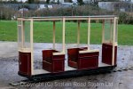
(I hope the folks at SRSL don't mind me showing their copyrighted image here for illustrative purposes only?)
This one really is only 5" gauge - and once overhauled, it seems to have worked for it's new owner pretty well too!
I just cannot resist the temptation - hence an earlier clearance experiment, mounted on Rich's superb running "gun trolley" bogies!
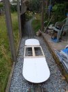
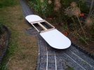
Good suspension will be absolutely critical for stability in this case - but at least I can be confident, thanks to those who have already done it, that it is quite feasible!
I will save any further details of the Tram for another thread - as and when serious work starts to get under way!
Pete.
This is the inspiration:

(I hope the folks at SRSL don't mind me showing their copyrighted image here for illustrative purposes only?)
This one really is only 5" gauge - and once overhauled, it seems to have worked for it's new owner pretty well too!
I just cannot resist the temptation - hence an earlier clearance experiment, mounted on Rich's superb running "gun trolley" bogies!


Good suspension will be absolutely critical for stability in this case - but at least I can be confident, thanks to those who have already done it, that it is quite feasible!
I will save any further details of the Tram for another thread - as and when serious work starts to get under way!
Pete.
Last edited:
Peter Insole
Western Thunderer
I couldn't agree more Cmax, that is why I suspect that the vendor is the more likely culprit!
Yes Tom, I will have to think again about the suspension arrangements on the Horwich loco!
Bringing the subject back to this thread: Both straps are now on, and I'm just about to make a start cutting and drilling some angle fittings - at least while my "noise" window is still open!
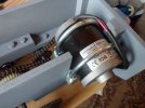
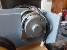
It is a bit tight in there, and there is not an awful lot of room to allow for sufficient chain tensioning, so it's all going to be a bit fun in the next couple of hours (?)!
Pete.
Yes Tom, I will have to think again about the suspension arrangements on the Horwich loco!
Bringing the subject back to this thread: Both straps are now on, and I'm just about to make a start cutting and drilling some angle fittings - at least while my "noise" window is still open!


It is a bit tight in there, and there is not an awful lot of room to allow for sufficient chain tensioning, so it's all going to be a bit fun in the next couple of hours (?)!
Pete.
Osgood
Western Thunderer
The outer race has a spherical face, as does the housing, in order to provide a swivelling movement for shaft alignment.Gosh and golly! They are big boys. I assume as they have grease nipples pressing the races out isn't going to work. Steel bodies like that would take a lot of fettling to make smaller blocks too.
By 'eck. What a conundrum.
Tom.
The bearing assembly comes out by turning the bearing at 90 deg to housing and rotating until the spot on the housing is reached where it will pop out.
The grease nipple feeds into an annular groove in outer race and via a hole into bearing, so does not need to be removed.
And the housings are cast iron.
So not easy to repurpose the bearing without using the housing in some way.
Peter Insole
Western Thunderer
I haven't posted progress for the last few days as any pictures would all look pretty much the same!
The main issue has been to get the three sets of shafts and bearings aligned in a relatively small space, so that there is appropriate tension on both chains. I have lost count of the number of times I had to sit and stare at it, and then strip it all back down again to make another adjustment!
Having added an additional block, the first part of the fun was trying to work out how on earth to drill the motor mounting holes into the frames dead square: There is not an awful lot of room to manoeuvre on my diddy workbench either... solid, bolted down or otherwise fixed things tend to keep getting in the way.
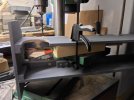
I also had to be careful to avoid existing screws in the frames - that had been driven in at points that seemed sensible at the time, but inevitably turn out to be in precisely the wrong place!
A pair of sturdy, steel angles eventually went in to form a platform to mount the motor. The original intention was to provide the motor with a degree of tensioning adjustment by slotting two holes in the mounts, but again found that space was a bit more limited than expected. Eventually, (!) I managed to work out that by adding shims, in this case strips of ply, under each of the reduction gear shaft bearings had the desired effect.
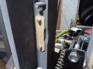
They will, I have no doubt, squeeze down and become less effective over time - but they should be cheap and easy enough to replace when the need arises?
Having satisfied myself that the drive was at last running true, I remembered to do a final, "belt and braces" job - that I had foolishly put off from earlier!
The main axle sprocket is an interference fit over the original nylon, final drive spur gear, (requiring the use of the bench vice to press it home) with a pair of grub screws to lock the hub onto the shaft. While the spur hub (in compression) cannot move on the hexagonal axle, the same could not be guaranteed for the sprocket. I am just not prepared to trust the grub screws not tearing the plastic.
I am reasonably confident that the nylon should be tough enough to be secure, and feel that there is enough meat on the spur web to hold some studs - after all, there are many 5" gauge locos routinely fitted with such final drive gears anyway?!
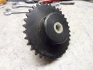
There is more than enough available steel in the sprocket hub behind!
(The above image shows how jammy the fit between the two parts turned out to be - almost as if it were designed that way?!)
I would have preferred four studs to better distribute the load , but yet again, there are existing bores in the sprocket hub, dictating a minimum of three!
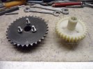
I could not find any washers of the size and depth to pack behind the dished section of the spur, so filed down three nuts instead. Whilst the task was fussy, a distinct benefit is that they had a locking effect on the studs. I have found that cutting threads by hand, with cheap (and not so cheerful) taps usually ends with a slightly sloppy fit!
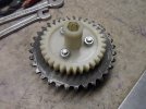
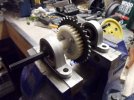
All in situ, and ready for the wheels to be pressed back on...
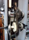
I put the battery box back on to counter the weight of the motor - which at the moment can too easily tip the loco up on it's rear end!
I rather think that some ballast will have to be added forward, although the battery itself should contribute some balance when installed.
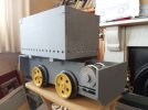
This was the state of play this morning, shortly before Rich came round...
He brought with him some electrical wiring, and a determination to see the little beast running by the time he had to pick the boys and girls up from school!
Between us, we succeeded too...
but more of that later...!
Pete.
The main issue has been to get the three sets of shafts and bearings aligned in a relatively small space, so that there is appropriate tension on both chains. I have lost count of the number of times I had to sit and stare at it, and then strip it all back down again to make another adjustment!
Having added an additional block, the first part of the fun was trying to work out how on earth to drill the motor mounting holes into the frames dead square: There is not an awful lot of room to manoeuvre on my diddy workbench either... solid, bolted down or otherwise fixed things tend to keep getting in the way.

I also had to be careful to avoid existing screws in the frames - that had been driven in at points that seemed sensible at the time, but inevitably turn out to be in precisely the wrong place!
A pair of sturdy, steel angles eventually went in to form a platform to mount the motor. The original intention was to provide the motor with a degree of tensioning adjustment by slotting two holes in the mounts, but again found that space was a bit more limited than expected. Eventually, (!) I managed to work out that by adding shims, in this case strips of ply, under each of the reduction gear shaft bearings had the desired effect.

They will, I have no doubt, squeeze down and become less effective over time - but they should be cheap and easy enough to replace when the need arises?
Having satisfied myself that the drive was at last running true, I remembered to do a final, "belt and braces" job - that I had foolishly put off from earlier!
The main axle sprocket is an interference fit over the original nylon, final drive spur gear, (requiring the use of the bench vice to press it home) with a pair of grub screws to lock the hub onto the shaft. While the spur hub (in compression) cannot move on the hexagonal axle, the same could not be guaranteed for the sprocket. I am just not prepared to trust the grub screws not tearing the plastic.
I am reasonably confident that the nylon should be tough enough to be secure, and feel that there is enough meat on the spur web to hold some studs - after all, there are many 5" gauge locos routinely fitted with such final drive gears anyway?!

There is more than enough available steel in the sprocket hub behind!
(The above image shows how jammy the fit between the two parts turned out to be - almost as if it were designed that way?!)
I would have preferred four studs to better distribute the load , but yet again, there are existing bores in the sprocket hub, dictating a minimum of three!

I could not find any washers of the size and depth to pack behind the dished section of the spur, so filed down three nuts instead. Whilst the task was fussy, a distinct benefit is that they had a locking effect on the studs. I have found that cutting threads by hand, with cheap (and not so cheerful) taps usually ends with a slightly sloppy fit!


All in situ, and ready for the wheels to be pressed back on...

I put the battery box back on to counter the weight of the motor - which at the moment can too easily tip the loco up on it's rear end!
I rather think that some ballast will have to be added forward, although the battery itself should contribute some balance when installed.

This was the state of play this morning, shortly before Rich came round...
He brought with him some electrical wiring, and a determination to see the little beast running by the time he had to pick the boys and girls up from school!
Between us, we succeeded too...
but more of that later...!
Pete.
Giles
Western Thunderer
Peter, I don't know if you're planning any wagons or anything, but I've got a few of these kicking round which I got for instant railway wheels (indeed I have a dinghy that lives on a sort of strange bogie wagon beside the house on 8 of these things 10 1/4"!).
They're only 50mm diameter across the tread, and mounted on M12 stud. The lube is somewhat stiff, but warming or some diesel in there will free them. The treads are flat of course. No coning....
Might some be any use?
They're only 50mm diameter across the tread, and mounted on M12 stud. The lube is somewhat stiff, but warming or some diesel in there will free them. The treads are flat of course. No coning....
Might some be any use?
Peter Insole
Western Thunderer
Oh wow Giles, yes please!
I understand that some folks refer to 7 1/4" as "Twelve inches to the foot, minimum gauge railways - rather than any specific scale? One of the things that I discovered about our line is that it has a practical use shifting heavy stuff in the garden, quite apart from being something purely for amusement, so maybe even our peculiar 5 3/4" qualifies? Having said that, I do have a plan for a couple of naughty, "novelty" wagons - that will hopefully be amusing for the children, (as well as grownups?) and to that end I have already set aside some more of the lightweight, moulded polypropylene wheels that would be ideal for that purpose.
However, a couple of "no frills" heavy duty, four wheeled wagons, that could be run singly, or connected flexibly to form a bogie bolster, would also unquestionably be a most welcome addition to the rolling stock fleet!
One of my sons; Mr.O., is the gardener amongst us, and he has a particular liking for plants and shrubs in pots that he can move around. So far, he has restricted himself to those which he can carry, but it is a long journey to lug anything all the way down to his potting shed, so I am fairly certain he would really appreciate some convenient form of conveyance too?!
Your wheels look absolutely ideal, and I cannot thank you enough for your kind offer!
Pete.
Peter Insole
Western Thunderer
Having promised to continue with yesterday's account, here is a bit more:
The proceedings were so exciting, that I completely forgot to grab my camera! Rich did record the tests however on his mobile, but the best I can show is a couple of low resolution screen-grabs - if R doesn't mind the cheek?!
Although the order is wrong, this next image shows how the temporary test rig was set up (minus the 12V battery):
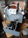
Rich and me were so keen to try out the loco under load, that despite an unrelenting drizzle coming down, we decided to cover the vulnerably exposed electrics with a clean, fresh rubble sack and take a chance!
I had after all previously declared that when completed, this loco should have an "all (but the worst) weather capability!"
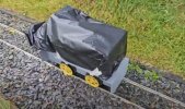
The contraption did look rather odd - and perhaps a bit like some form of anti-commercial/industrial espionage measures had been applied?! It did succeed in keeping all the important stuff dry though!
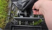
There was some amusement to be had on two counts:
First, blindly searching for the dangling controls, let alone twiddling a miniature potentiometer under the covers - especially difficult for Rich, one handed when trying to hold his mobile with the other!
(No, stop smirking you naughty peoples)!
Secondly: Without couplings, the outward journey relied on pushing the tender, but for reasons that I will describe in a moment, the return trip required holding on with one extended finger!
(Right, that does it)!
Seriously though, I am damned glad we did it in such wet conditions, as it revealed some very interesting points for consideration!
The main concern had been whether our 100W motor would be up to the task. Surprisingly, there is not an awful lot of information published out there on the web, where it would seem few are prepared to discuss such matters. On the rare occasion that they do, most seem to strongly advise using nothing less than 150W, or sometimes more - and then only when paired!
Well - the little beastie turns out to be a flyer - in more than one sense! There is definitely no issue with stalling from a start or climbing our gradients! There seem to be bags of reserve power under there - quite enough for us anyway! It is a bit of a growling animal - that is fearsomely fleet of foot too! Every witness unanimously agreed that some kind of limiter or governor would have to be installed to prevent small persons from potentially becoming airborne!
Despite having attempted to reduce the axle speed with an extra gear shaft and sprockets, I will clearly need to reconsider the ratios! Otherwise, there can be no doubt that if the minors do manage to stay on board, especially at the top curve, they could traverse the entire circuit in a matter of seconds! Surely great for the them young'ns, but for us boring old fa... I mean grownups, we fear the likely consequences!
I know I have mentioned several times before that Mr. O., is our keen gardener, but it has to be said that he is a fair weather one - so not quite that keen! He will never be caught in a Sou'wester, wax coat or wellies! As a result of that, and the fact that he has been engaged in other vital spare time duties, the railway has taken on a slightly overgrown - if delightfully bucolic aire! It may be a charming re creation of a narrow gauge byway, but the combination of copious moisture and squished foliage is absolute murder on the motion!
At the moment, it is not so much the horsepower, but traction that is the big problem. While I am aware of hoping too much that a single powered axle (with traction tyre) might have been sufficient - the hopelessly spinning wheels on the slightest deviation from dead level (despite the prevailing conditions) clearly prove me to have been overly optimistic! Matters were marginally aided by leaning forward on the driving truck and placing downward pressure on the loco battery box with my free arm and hand, but it is abundantly clear that the engine, even when completed, will still be far too light. The crazy thing is that we have just had (by an extraordinarily generous gift) our old, original but desperately draughty sash windows replaced, and the contractors quickly removed the remains - including what could have been handy in the form of the cast iron counterweights! Eternally grateful in my dotage for the comforts of double glazing, I may be, but damn and blast it, I shall have to search for something else similarly compact and dense for suitable ballast now!
The addition of more sprockets and using the remainder of our obtained chain to couple both axles should have been part of the plan in the first place! A priority now is to order a larger gear for the drive train to lower the top speed a bit further, while another to match the original reducer, and fitted to the leading axle, plus some extra links, should do the job nicely - and perchance, to tame the wild thing just a tad?!
Pete.
The proceedings were so exciting, that I completely forgot to grab my camera! Rich did record the tests however on his mobile, but the best I can show is a couple of low resolution screen-grabs - if R doesn't mind the cheek?!
Although the order is wrong, this next image shows how the temporary test rig was set up (minus the 12V battery):

Rich and me were so keen to try out the loco under load, that despite an unrelenting drizzle coming down, we decided to cover the vulnerably exposed electrics with a clean, fresh rubble sack and take a chance!
I had after all previously declared that when completed, this loco should have an "all (but the worst) weather capability!"

The contraption did look rather odd - and perhaps a bit like some form of anti-commercial/industrial espionage measures had been applied?! It did succeed in keeping all the important stuff dry though!

There was some amusement to be had on two counts:
First, blindly searching for the dangling controls, let alone twiddling a miniature potentiometer under the covers - especially difficult for Rich, one handed when trying to hold his mobile with the other!
(No, stop smirking you naughty peoples)!
Secondly: Without couplings, the outward journey relied on pushing the tender, but for reasons that I will describe in a moment, the return trip required holding on with one extended finger!
(Right, that does it)!
Seriously though, I am damned glad we did it in such wet conditions, as it revealed some very interesting points for consideration!
The main concern had been whether our 100W motor would be up to the task. Surprisingly, there is not an awful lot of information published out there on the web, where it would seem few are prepared to discuss such matters. On the rare occasion that they do, most seem to strongly advise using nothing less than 150W, or sometimes more - and then only when paired!
Well - the little beastie turns out to be a flyer - in more than one sense! There is definitely no issue with stalling from a start or climbing our gradients! There seem to be bags of reserve power under there - quite enough for us anyway! It is a bit of a growling animal - that is fearsomely fleet of foot too! Every witness unanimously agreed that some kind of limiter or governor would have to be installed to prevent small persons from potentially becoming airborne!
Despite having attempted to reduce the axle speed with an extra gear shaft and sprockets, I will clearly need to reconsider the ratios! Otherwise, there can be no doubt that if the minors do manage to stay on board, especially at the top curve, they could traverse the entire circuit in a matter of seconds! Surely great for the them young'ns, but for us boring old fa... I mean grownups, we fear the likely consequences!
I know I have mentioned several times before that Mr. O., is our keen gardener, but it has to be said that he is a fair weather one - so not quite that keen! He will never be caught in a Sou'wester, wax coat or wellies! As a result of that, and the fact that he has been engaged in other vital spare time duties, the railway has taken on a slightly overgrown - if delightfully bucolic aire! It may be a charming re creation of a narrow gauge byway, but the combination of copious moisture and squished foliage is absolute murder on the motion!
At the moment, it is not so much the horsepower, but traction that is the big problem. While I am aware of hoping too much that a single powered axle (with traction tyre) might have been sufficient - the hopelessly spinning wheels on the slightest deviation from dead level (despite the prevailing conditions) clearly prove me to have been overly optimistic! Matters were marginally aided by leaning forward on the driving truck and placing downward pressure on the loco battery box with my free arm and hand, but it is abundantly clear that the engine, even when completed, will still be far too light. The crazy thing is that we have just had (by an extraordinarily generous gift) our old, original but desperately draughty sash windows replaced, and the contractors quickly removed the remains - including what could have been handy in the form of the cast iron counterweights! Eternally grateful in my dotage for the comforts of double glazing, I may be, but damn and blast it, I shall have to search for something else similarly compact and dense for suitable ballast now!
The addition of more sprockets and using the remainder of our obtained chain to couple both axles should have been part of the plan in the first place! A priority now is to order a larger gear for the drive train to lower the top speed a bit further, while another to match the original reducer, and fitted to the leading axle, plus some extra links, should do the job nicely - and perchance, to tame the wild thing just a tad?!
Pete.
Last edited:
Peter Insole
Western Thunderer
After all the fun we had with our rather soggy, slithering test session, I felt that sorting out the drawgear was a fairly high priority!
The original "BEV" locomotives were supplied from the factory with a wide, curved, fabricated steel buffer, mounted on a backing plate with a bracket for a bar, or chain link and pin coupler. Individual customers appear to have adjusted the drawbar height by either drilling new holes in the headstocks, or simply turning the whole assembly upside down! While it would be nice to make working replicas of those original fittings, I don't really want to spend much more time on this one - so am quite happy to follow the lead set by at least one owner of a prototype! At some time or other, the original couplers had been replaced with two angles, set one above the other, and I felt a version of that would provide an ideal alternative for our own purposes!
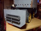
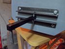
Admittedly, a rather inelegant solution, but nonetheless entirely practical.
The width of the angles does seem to be a bit excessive, but it turns out that the design of the parts on the prototype are quite convenient: The genuine article is constructed from unequal angle, with the larger sections facing outward. The central coupling pin hole is near the root, and there are two holes near the extremities on either side - drilled nearer the outer edges. That peculiar arrangement only made sense after I installed a temporary drawbar, (borrowed from the Horwich engine) and it then became obvious that the long slot created by the angles acts as a safe containment for the coupling bar when out of use. The additional holes were for another pin to be dropped in to prevent the bar from swinging about and possibly causing, or getting damaged! A very neat idea - although as you can see, I haven't bothered with the latter part - my excuse being that only equal angle was readily available!
I have emulated the width though, primarily because on the rear headstock, the motor mountings got in the way of the fixing bolts and nuts behind! Besides, the extra metal required for bolting outside the frames very much adds to the overall strength of the structure - something quite essential, bearing in mind a potential for the odd collision, (or two) as an almost inevitable result of being operated by excitable juveniles... and in an environment where the rolling stock fleet is soon, hopefully to be notably enhanced!
Pete.
The original "BEV" locomotives were supplied from the factory with a wide, curved, fabricated steel buffer, mounted on a backing plate with a bracket for a bar, or chain link and pin coupler. Individual customers appear to have adjusted the drawbar height by either drilling new holes in the headstocks, or simply turning the whole assembly upside down! While it would be nice to make working replicas of those original fittings, I don't really want to spend much more time on this one - so am quite happy to follow the lead set by at least one owner of a prototype! At some time or other, the original couplers had been replaced with two angles, set one above the other, and I felt a version of that would provide an ideal alternative for our own purposes!


Admittedly, a rather inelegant solution, but nonetheless entirely practical.
The width of the angles does seem to be a bit excessive, but it turns out that the design of the parts on the prototype are quite convenient: The genuine article is constructed from unequal angle, with the larger sections facing outward. The central coupling pin hole is near the root, and there are two holes near the extremities on either side - drilled nearer the outer edges. That peculiar arrangement only made sense after I installed a temporary drawbar, (borrowed from the Horwich engine) and it then became obvious that the long slot created by the angles acts as a safe containment for the coupling bar when out of use. The additional holes were for another pin to be dropped in to prevent the bar from swinging about and possibly causing, or getting damaged! A very neat idea - although as you can see, I haven't bothered with the latter part - my excuse being that only equal angle was readily available!
I have emulated the width though, primarily because on the rear headstock, the motor mountings got in the way of the fixing bolts and nuts behind! Besides, the extra metal required for bolting outside the frames very much adds to the overall strength of the structure - something quite essential, bearing in mind a potential for the odd collision, (or two) as an almost inevitable result of being operated by excitable juveniles... and in an environment where the rolling stock fleet is soon, hopefully to be notably enhanced!
Pete.
Peter Insole
Western Thunderer
Apparently, this is an extremely rare, indeed almost extinct species these days - and I actually managed to come across a fresh, and fully grown example!
All I have to do is complete the remaining structural details (!) to begin the big paint job! I have already made a start - and at the same time executed a slight change of plan - by getting some new primer on the battery box and lid:
Perhaps I should warn you all, dear readers and viewers, that the following images might appear unexpectedly garish?
The method in my madness is (I like to think) twofold, in that while a bright yellow finish should really be applied over a white primer/undercoat, I don't particularly want to feel the need to wear sunglasses whenever gazing in the direction of the completed product! I am also under the impression that BEV pre treated their products with red oxide, so what with birds, stones, and all that; the result should hopefully present a marginally less gaudy visual impact, plus any subsequently acquired dings and scratches might show a rusty shade underneath?
We shall see.
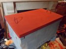
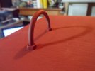
Anyway, an embellishment of the otherwise rather plain lid of the box was required before I could apply any paint - although it has left me in the horns a slight dilemma:
I am perfectly aware that by placing, albeit prototypical, and rather handy handles atop the machine would be awfully tempting for small persons to interfere with - and in so doing, potentially come into shocking contact with 12 volts, at a maximum pressure of 20 amps! However, I also don't want to encourage anyone to try sitting on top of the loco when in transit either! Once the four, large lifting lugs, plus a nice and noisy (not quite sure why I am volunteering for that!) bulb horn is fitted thereon to deal with the latter issue, I suppose some form of lock or latching device will have to be considered before letting the "throngs" loose with it?
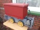
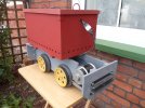
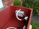
I will be looking for some kind of appropriate, flexible, water and tamper proof cover for the exposed section of cable extending from the box to the intended, but not yet constructed control stand!
Meanwhile, where on earth did I put that lovely, luxuriously new paint brush to go with the joyously procured tin...?!
Pete.

All I have to do is complete the remaining structural details (!) to begin the big paint job! I have already made a start - and at the same time executed a slight change of plan - by getting some new primer on the battery box and lid:
Perhaps I should warn you all, dear readers and viewers, that the following images might appear unexpectedly garish?
The method in my madness is (I like to think) twofold, in that while a bright yellow finish should really be applied over a white primer/undercoat, I don't particularly want to feel the need to wear sunglasses whenever gazing in the direction of the completed product! I am also under the impression that BEV pre treated their products with red oxide, so what with birds, stones, and all that; the result should hopefully present a marginally less gaudy visual impact, plus any subsequently acquired dings and scratches might show a rusty shade underneath?
We shall see.


Anyway, an embellishment of the otherwise rather plain lid of the box was required before I could apply any paint - although it has left me in the horns a slight dilemma:
I am perfectly aware that by placing, albeit prototypical, and rather handy handles atop the machine would be awfully tempting for small persons to interfere with - and in so doing, potentially come into shocking contact with 12 volts, at a maximum pressure of 20 amps! However, I also don't want to encourage anyone to try sitting on top of the loco when in transit either! Once the four, large lifting lugs, plus a nice and noisy (not quite sure why I am volunteering for that!) bulb horn is fitted thereon to deal with the latter issue, I suppose some form of lock or latching device will have to be considered before letting the "throngs" loose with it?


I will be looking for some kind of appropriate, flexible, water and tamper proof cover for the exposed section of cable extending from the box to the intended, but not yet constructed control stand!
Meanwhile, where on earth did I put that lovely, luxuriously new paint brush to go with the joyously procured tin...?!
Pete.
Dog Star
Western Thunderer
And with future content relating to this model being posted in the "Over Eastsidepilot's garden" topic?I reckon you'll need to fit one of these to the lid if that thing behaves like you suggest
Peter Insole
Western Thunderer
Peter Insole
Western Thunderer
I found the brush, so opened the tin and dipped it in!
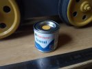
Oh wow! Sunglasses needed? Perhaps welder's eye protection might be more appropriate?! The tin might carry the old stock number, but this stuff is the latest Hornby formulation - and I can only assume that they are (maybe in desperation?) trying to appeal to new markets and more modern tastes?
While the quality of Humbrol paints has, to put it mildly, been somewhat variable over the years, at least the original gloss shades - when available - seemed to have remained fairly constant?! The yellow (69) may have been a version of - or something in the order of "Chrome Yellow", but it had always struck me as being a tad greyish! This is perhaps not quite so surprising, as some of the most popular colours of the 1960's and early 70's were actually like that!
Not this new mixture though! It is borderline fluorescent - and that is without a white primer/undercoat!
Who remembers the childhood summertime game of holding a buttercup under a friend's chin, and asking them if they liked butter? Well, this stuff is so bright it reflects off the ceiling - and quite a lot else in the room - even on a dull day!
I should point out that neither my camera or monitor seem to be able to cope with, or even get remotely close to the astonishing brilliance!
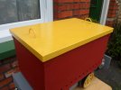
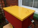
You can just make out the original, earlier shade for comparison on the front and rear wheels in the two images above!
The battery box lid now turns out to be a very close match for these delightful things ("Jerusalem Artichoke") that every season bring so much cheer to our little, pocket handkerchief front patch:

A myriad of sunny flower heads amongst the dull green foliage is one thing, but a large(ish) and solid lump of locomotive, fully clad in such a shade, might prove to be a bit of an overwhelming sight in any environment?!
Now that I have reduced the content of the tin a bit, there will be room to mix in another colour - I am considering using a light brown - to curb some of the glare! During construction, and right up to the point of applying the first coat, I had occasionally wondered whether to attempt a full-on weathering job, with lots of rust patches blowing through the paint surfaces and streaks of oxide running down the sides, but the sheer scale of the task kept putting me off!
Now the lid has a couple of coats all over, it might be too late to create anything remotely convincing anyway, (?) so hopefully just a subtly "knocked down" finish will suffice?!
However it ends up, there will certainly be no excuse if anyone steps into the path of this particular "speeder" anyway!!
Pete.
Oh wow! Sunglasses needed? Perhaps welder's eye protection might be more appropriate?! The tin might carry the old stock number, but this stuff is the latest Hornby formulation - and I can only assume that they are (maybe in desperation?) trying to appeal to new markets and more modern tastes?
While the quality of Humbrol paints has, to put it mildly, been somewhat variable over the years, at least the original gloss shades - when available - seemed to have remained fairly constant?! The yellow (69) may have been a version of - or something in the order of "Chrome Yellow", but it had always struck me as being a tad greyish! This is perhaps not quite so surprising, as some of the most popular colours of the 1960's and early 70's were actually like that!
Not this new mixture though! It is borderline fluorescent - and that is without a white primer/undercoat!
Who remembers the childhood summertime game of holding a buttercup under a friend's chin, and asking them if they liked butter? Well, this stuff is so bright it reflects off the ceiling - and quite a lot else in the room - even on a dull day!
I should point out that neither my camera or monitor seem to be able to cope with, or even get remotely close to the astonishing brilliance!


You can just make out the original, earlier shade for comparison on the front and rear wheels in the two images above!
The battery box lid now turns out to be a very close match for these delightful things ("Jerusalem Artichoke") that every season bring so much cheer to our little, pocket handkerchief front patch:

A myriad of sunny flower heads amongst the dull green foliage is one thing, but a large(ish) and solid lump of locomotive, fully clad in such a shade, might prove to be a bit of an overwhelming sight in any environment?!
Now that I have reduced the content of the tin a bit, there will be room to mix in another colour - I am considering using a light brown - to curb some of the glare! During construction, and right up to the point of applying the first coat, I had occasionally wondered whether to attempt a full-on weathering job, with lots of rust patches blowing through the paint surfaces and streaks of oxide running down the sides, but the sheer scale of the task kept putting me off!
Now the lid has a couple of coats all over, it might be too late to create anything remotely convincing anyway, (?) so hopefully just a subtly "knocked down" finish will suffice?!
However it ends up, there will certainly be no excuse if anyone steps into the path of this particular "speeder" anyway!!
Pete.
Last edited:
Tom Insole
Western Thunderer
Dog Star
Western Thunderer
Is that image from one of the Foyle's War programmes?I guess that's one way to battle the winter blues and early sunset... Make your own sun!


