7mm Finney7 West Country - 34023 Blackmore Vale

Ash Pan and Injectors
  • 7mmMick

    Western Thunderer
    Right, to progress.....

    Whilst the heavy duty crankpins are away being turned down I can't do anything with the brake rigging etc so I set to work on the rear injectors. About this time @Rob Pulham posted a thread on some excellent pictures of Winston Churchill at Shildon, I duly had a good look around them and noticed the ash pan is the original Southern one. This gave me that enormous sinking feeling. A quick look at Blackmore Vale confirmed that she was fitted the same, in fact still in as of now. WHY OH WHY did I build the bloody BR ash pan??:headbang: Probably some misconceived idea that all Light Pacifics were so fitted later in life. In my defence I built the BR ash pan on holiday in France in a frenzy over a couple of days. Here's the link to Rob's pictures to show what it should look like;

    Photo - Winston Churchill Battle of Britain Class

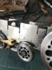
    And here's where we are now, NO BR ash pan in sight;
    DSCF4395.jpg DSCF4398.jpg

    I've set the dampers as per Winston Churchill, which to me look like they're just cracked open, which works for forward running if I remember? Forward running, front cracked open, rear fully open?? Having now studied the pictures for some time this area of the kit really captures the prototype perfectly, down to pressing the rivet out to represent the round bolt head on the lower damp door stop. Like the BR ash pan this takes some time but to be honest I found it the easier of the two.

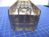
    Next onto the injectors and steam generator;
    DSCF4396.jpg

    What you see here are ten individual cast parts and four etched parts to build this assembly. @oldravendale leant me the 'Book of West Country and Battke of Britain Pacifics' as being a North Eastern man I have no research material on the class. The rear of the book has a number of detail pictures (presumed from an accident report) of 253 Squadron on her side. These pictures are great for modelling this area. The pipe runs are yet to be fitted as the casing needs to be in place to get these accurate. When the time comes I'll refer to these again. My next job on the frames was to start making up the axle box springs but more on this another day.
     
    8' 6" V Cab
  • 7mmMick

    Western Thunderer
    To break up the monotony of laminating the axle box springs I decided to make a start on probably the most difficult area (purely my perception) of the build. I wanted to get it out of the way as it's the one part I was loosing sleep over. And this is why I know where @Pencarrow is coming from:D.

    The instructions advised to have a test run on the other spare cab, so out came the 9' cab and away I went with the rivet press and rolling bars. Bugger me I trashed the thing, intentionally I might add. There are rows of very close double rivets and rivets at the edge of the side sheets, these were very difficult to work. I tried a number of rivet press combinations and found one that worked. So I was now happy with my rivet pressing. With some card added to protect the rivet definition I whizzed it through the bars and was happy. With that exercise complete I moved onto my chosen cab.

    If this is your first time at this kit PLEASE ruin a spare cab first as you'll probably bugger up your chosen one if you go straight at it.

    The cab for Blackmore Vale is the 8' 6" V Cab. Being one of the early conversions my chosen cab is the @mickoo Finney7 addition to the kit. So off I went pressing rivets and rolling away. I had good reason to loose sleep. This is a difficult area and not for the faint hearted. That said if you take your time and have the odd break it goes really well. The kit is designed with helpful fold lines on the tight curves to assist forming, these work really well but can catch you out. One tip, don't roll onto then when you roll the top of the cab roof. You end up with a nice straight fold line, which can be removed but is a total pain! Also when you form the tighter curves be really careful and tease it round a bit at a time, otherwise you can end up with a hexagon type bend. I also wouldn't risk annealing any of the cab at all, I'm not a fan in any case but it's a really bad idea with this cab.

    Those lessons out of the way the cab was a joy to build. The shape around the V windscreen is complex to bend and I thought this would be a problem area. Not so. When it came to fitting the windscreen front they dropped straight into place. Everything fitted perfectly, which is impressive kit design. I grabbed a quick photo on my phone to show you;

    IMG_1164.jpg
    The kit provides a centre strengthening plate for these front screens and the rear. This is a neat idea which makes life much easier. So the main cab frame together, it doesn't look much but there's a few hours work here;
    DSCF4390.jpg
    The other side with the windscreen cleaned up. I decided on this side to fold out the sight screen to add strength to the window bar. I would recommend against this until the last minute as all you end up doing it bending it more when you lay the cab on it's side;
    DSCF4388.jpg
    It's difficult to photograph the cab in brass as the light catching it makes it look worse than it is. The windscreen curves are smooth I promise:thumbs: The customer has also chosen to fit the cab roof framing, supplied as an extra. Having read @mickoo thread I maybe should have fitted this in the flat. I opted not too as I thought it would over complicate the rolling process. I chose instead to fit it at this stage before I go any further. I first rolled it to shape, using thick card to support the framework, whilst still on the fret;
    IMG_1165.jpg
    I then tried to get it into the cab. The fitting of the rear floor makes this impossible, but you have to fit the floor to finish the main cab structure. The answer, like Mick's build was to split it into three. I carefully nipped the lower sides off, fitted the roof section first, centralising with the cab roof vent and then the two sides. This took a good couple of hours and a further hour to clean up. I personally think it's really worth the effort for the extra detail;
    DSCF4392.jpg
    DSCF4393.jpg
    Ok so the clean up's not perfect but it is really difficult getting in with the scratch brush :p

    I couldn't resist sitting the cab on the rear to grab a shot of the Light Pacific profile;
    DSCF4399.jpg
    Next back to the axle box springs in between cab detailing,

    Mick
     
    Bulleid 4500G Tender
  • 7mmMick

    Western Thunderer
    Back to it in the New Year. I must try and find more time to post progress. We left the build here on the cab construction. I did push further with that and with the wheels in the frames, the cab and casing sat together Blackmore began to take shape. From my bench my in progress models sit at eye level, which helps both motivate and allows me to glance again and again to make sure all lines up properly. I kept looking at the lone loco and thought things didn't look right, so I decided to crack on with the tender........

    4500G Tender in Original condition ( minus the TIA system as this was long gone by 61' )

    I'm using the Finney7 inner tender frame to carry the Slater's insulated horn blocks. It's a straight forward fold up job and takes only a few minutes to get together. Here's the basic frame;
    DSCF4418.jpg

    The two cross members are tacked on, located by a slot and tab for accuracy. Because i'm using the 5/32 axle tender wheels I needed to make the brake gear removable. I used some 1.2mm brass tube to make a spacer for each brake hanger and the brake gear just simply pings in and out. It looks a simple set up but there's quite a bit of work here getting all the alignment just so and building up the components from many laminations !
    DSCF4419.jpg
    Next, horn blocks and wheels. I've fitted the Finney7 etched overlays, which ( In my unbiased opinion;) ) are excellent and really enhance the look of the wheels. Once fitted the brakes are popped over;
    DSCF4421.jpg
    I haven't got around to fitting the 12Ba bolts and springs to the inner frame but this is not a big job. Just that to do and split the axles, add pick up wires and it's all done. Next I moved onto the main frames. I've strayed away from a blow by blow account as it's almost a straight kit build. The one thing I did do was take @mickoo up on his advice and make the rear buffer beam removable, so that the captive buffers can be added post painting;
    DSCF4430.jpg
    Remembering to drill out the tank base before going much further so that there's no fit issues later;
    IMG_1375-2.jpg
    The completed frames. Again there's lots of small etched parts here, especially the rear, where it's all going on. Lots of fabrication needed but well worth the burnt finger ends and fibre stick shards in the end:D;DSCF4426.jpg
    DSCF4423.jpg
    DSCF4427.jpg
    And finally the inner and outer frames together;
    DSCF4435.jpg
    Next job was the tender tank........
     
    Bulleid 4500G High Rave Tender Tank
  • 7mmMick

    Western Thunderer
    The tank was a straight kit build. The build process advises building up the rear, centre and forward bulkheads and hopper first. This needs to be absolutely bang on so everything else fits just so later when the sides go on. It's well worth taking your time here and double and triple checking. The forward bulkhead has lots of small etched parts and pipe runs. The kit allows you to build this in the flat, which is much easier. I left off a couple of pipe runs and fitted them later, I WISH I hadn't:headbang:I still have the remainder of the tender coal space slacking pipe to fit and can't wait :D;
    DSCF4437.jpg
    A bit more cleaning up needed around the coal chute.
    DSCF4438.jpg
    @Dikitriki gave me some great advice for adding the tank sides. The kit advises fitting the vertical strengthening ribs after the sides are on. DO NOT do that, fit them before hand as it makes life a million times easier as you're working on the flat and it's straight forward. I wouldn't fancy fitting the ones between the coal space and the tank side once the sides are fully fitted!
    The tender back. Fun and games indeed with the .45mm conduit for the electric lighting. I broke more than one drill bit drilling out the lamps and the junction boxes. How the carpet monster didn't gobble up the junction boxes is beyond me as they're tiny and if they ping from the pliers they're gone forever:)). There's a neat little jig for the ladders, which at first glance looks a pain but in reality is straight forward, with the help of some blue tack ( other brands available :D )

    IMG_1381.jpg
    IMG_1382.jpg
    IMG_1383.jpg
    DSCF4441.jpg
    A bit more cleaning to do here yet. So put all the lot together and you have an almost complete tender for Blackmore Vale. I just need to add the cab doors, Window frames (post paint), slicing pipe and sanding pipes;
    DSCF4453.jpg DSCF4452.jpg DSCF4445.jpg DSCF4444.jpg DSCF4456.jpg
    Oh and polish those steel buffers!!

    Now back to the loco as it now has something resembling a tender to pull!

    Mick
     

    Attachments

    • DSCF4441.jpg
      DSCF4441.jpg
      86.3 KB · Views: 8
    Front end detail
  • 7mmMick

    Western Thunderer
    Thanks for the photo's chaps, still pondering whether to fit the drain pipe or not?

    As promised back to the loco. The frames are well on the way and I got to the stage where I needed the basic body structure together to make sure everything fits and especially to get a good join where the casing meets the cylinder covers. To get to that stage the front end needs to be on and the cab. So firstly the later style front end is fabricated and detailed as a separate assembly. Also fitted is the AWS gubbins which comes as a separate kit for the later BR locos. I especially enjoyed forming the top cover and then fitting it. It's made from 5 thou brass and requires a sharp bend to lip over the front, lots of burnt fingers and tiny bits of filling required here and there:rant:.

    DSCF4461.jpg
    The lighting conduit is thankfully still through the frame holes and not across he footplate as some had. I spent time forming the coupling hook on the front buffer beam and straightening every time it got bent. Only to remove it as the AWS plate replaces it! The bottom part of the deflectors are not yet fully fitted as I think they'll still need minor adjustment once the assembly is permanently fitted to the casing.
    DSCF4458.jpg
    You can see the two holes where self tappers hold the footplate to the casing.

    In the background I have been pushing on with cab detail and have fitted the roof vents and exterior detail. The roof vent is cracked open as the enclosed Bulleid cab needs some fresh air on those warm Cornwall afternoons. The cab light castings are now Lost Wax and not White Metal as they were previously.;
    DSCF4478.jpg
    The footplate strengthening webs are also complete, along with window gutters and i've made a start on the cab door fixings;
    DSCF4479.jpg
    It's a bit grotty under there, but just tarnishing I promise:thumbs: A couple of shots of the body taking shape. I couldn't resist cleaning up the smoke box door and putting it in place for now.
    DSCF4469.jpg
    DSCF4473.jpg
    This is as far as the body needs to go for now. Next onto finishing off the frames as that's where the majority of the remaining work is needed. Once that's complete body detailing can commence,

    Mick
     
    Cab
  • 7mmMick

    Western Thunderer
    Whilst work continues with the chassis i've taken a break and had a couple of days working on the body. I think the resin moulding lulled me into a false sense of security as I thought there wasn't much work here! So firstly I finished off the cab area. There are a number of sub assemblies to make up on the bench before they are installed, the reverser;
    DSCF4769.jpg
    And then the injector taps. I've not yet fitted the slacking pipe as this will be one of the final details and will probably rest in a metal bucket. This is how I remember 92 Squadron being on the NYMR when I volunteered there. I also remember how important the slack pipe was!! Every ex BR man liked a clean footplate and the slacking pipe seemed to be in constant use!
    DSCF4768.jpg
    Fitted to the cab;DSCF4772.jpg
    DSCF4774.jpg
    I found this site a real help when fitting the cab out, although the image can make you feel a little sick if you let in run too long , it can be paused:D:thumbs:
    Blackmoor Vale 21C123
    All roof details and internals are now complete;
    DSCF4770.jpg
    DSCF4771.jpg
    As you have probably noticed I've opted for the @mickoo method for securing the backhead. I'll let the pictures do the talking but needless to say this makes life so much easier and will allow me to continually check the fit of the pipe work as there's a lot to squeeze in!
    DSCF4776.jpg
    DSCF4778.jpg
    I used some spare brass angle and 8BA nuts and bolts to knock up the fitting.
     
    Casing
  • 7mmMick

    Western Thunderer
    I then moved onto the casing and fitted the overlays and side ladders. The ladders are very fiddly indeed and are really flimsy without the pins. Once the pins (0,6mm brass wire) are fitted they are very sturdy. I took a couple of bench shots with the phone to illustrate;
    IMG_1666.jpg
    IMG_1667.jpg
    @mickoo advised to grind a small recess in the casing at the pin location. This allows a 'blob' of solder to remain on the rear of the pin without effecting the fit of the ladder. If you don't do this then the tiny amount of solder holding the pin just isn't enough. You also need to fit the inspection covers pre final fitting of the ladder. I've tried to solder as much as possible away from the resin before fitting as that way you know it's well fixed. Overlays in place, just two more small ones at the front to fit;
    DSCF4785.jpg
    DSCF4781.jpg
    The overlay around the chimney is not straight forward and takes some time and fettling to fit properly, I made this up as a sub assembly on the bench and made sure the joints were all well soldered. And finally I've added the smokebox door details. Working from my picture of 34023 I've adjusted the smokebox door handles, it's no good having it the same as all the other Finney BLP's out there :D
    DSCF4782.jpg
    All that's left ( I say all, it will be a couple of days work!!) on the body are the smoke deflectors and the pipe runs for lubricators and lights at the front end. Chassis update soon and it's looking almost there !

    Mick
     
    Pipework
  • 7mmMick

    Western Thunderer
    So enough on the body work for now, i've also been working on the frames. I've opted for the removable brake gear as per the kit instructions, my only slight deviation is that I've soldered a 12Ba nut on the inside of the frame as I wasn't confident that the taped frame would last regular stripping of brake gear, it may not be needed but i'd rather have it than the headache of a stripped thread once painted!
    DSCF4789.jpg
    Like @dibateg I've opted to replace some of the punched rivet detail with brass rod as it really does alter the look of the brake gear. @Rob Pulham has some excellent photos of Winston Churchill on Filckr and they've been invaluable for the bottom end build detail. he has kindly allowed me to use them here. The front stretched has etched ends and replacing them with rod makes it look a lot better and much more like this;30458636768_b294e8ecf3_o.jpg
    Once the brake gear was sorted I went onto fit the motor and gearbox which is a Maxon and ABC combined unit. I then found that there was no room for the width of the gearbox between the hornblocks and compensation arms. Cutting down the gear box is not an option so I followed the advice of @Dikitriki and cut down the hornblocks and guides to allow room for the gear box and side play. I soldered on some .64mm square brass bar to ensure the compensation arms would not slip off;
    DSCF4790.jpg
    A large void to accept the gearbox and everything still works as planned. You can also see the 12Ba nuts for the brake gear. Once inside the frames I found that if I set up the gearbox at 90 degrees the motor can was a tight fit in the frames, stopping side play! So I modified the spare motion bracket and with some brass wire mounted the motor at an angle that would fit inside the body well and allow side play;
    DSCF4817.jpg
    DSCF4805.jpg
    So the frames are at the stage where they only need a few jobs to finish, Sand pipes, speedo and those iconic pipe runs! Again i've used Rob's photos to start running in the pipe work. I'm going for the untidy BR used effect:D
    44277463962_27b28e2bd0_o.jpg
    44325392331_d3ab6b83c8_o.jpg
    DSCF4809.jpg
    I need to separate the smaller pipes a little more but you get the idea. Crosshead lubrication is finished, as are the cylinder covers. The kit suggests scribing in the inspection panel in the cylinder casing so I thought i'd have a go as looking at 34051 it is an obvious detail;
    30458634278_4c42972fc6_z.jpg
    DSCF4808.jpg
    Cylinder taps are all drilled to accept the copper pipe and once they're fitted that completes the scene here. Smoke deflector fitted with blue tack for effect only at the minute, it WON'T be wonky when finished :))

    A couple of final shots to show progress, the finish line is close:thumbs:
    DSCF4810.jpg
    DSCF4812.jpg
    DSCF4814.jpg

    Can't keep the brass shinny BTW, sorry:D

    Mick
     
    Finished...........almost
  • 7mmMick

    Western Thunderer
    Right, since my last post i've been spending all my spare time getting Blackmore Vale to the finishing post and dare I say I think i'm almost there. @Paul Moore will be treating her to her green overcoat and he asked that I paint the frames first as it makes things much easier. I completely understood where he was coming from as the chassis is a minefield of BA screws and bits that come on and off. So to get to this stage I needed to finish all the pipe runs and finalise those little jobs to ensure that the 6ft radius curve wouldn't cause an issue. I decided to remove some material behind the bogie to save any issues with the aft wheel touching the frame;
    IMG_1634.jpeg
    Marked out roughly what I needed to remove. It well hidden behind the bogie splasher now!
    IMG_1635.jpeg
    And finally on the fettling stage I decided for the low budget approach to maintaining downforce in the curves on the delta truck. One piece of 0.5mm phosphor bronze wire each side, seems to do the trick?
    IMG_1691.jpeg
    The tender frames were painted and the buffer beam left in primer for Mr Moore to turn red;
    DSCF4847.jpg
    Cab doors and final pipe runs added too;
    DSCF4846.jpg
    Pick ups are through the tender only with @Steph Dale split axles;
    DSCF4848.jpg
    And now the loco chassis in paint and motor/gearbox fitted, I used maskol where I could to keep the pipe runs and lubricators clean of paint;
    DSCF4843.jpg
    DSCF4845.jpg
    DSCF4832.jpg
    DSCF4833.jpg
    And finally some gratuitous shots;
    DSCF4835.jpg
    DSCF4841.jpg
    DSCF4830.jpg
    And finally I couldn't resist one with the headboard;
    DSCF4837.jpg
    It's not quite straight but I've left the brackets a little room for a snug fit when painted. Last job, the back head......
     

    Attachments

    • IMG_1632.jpeg
      IMG_1632.jpeg
      91.7 KB · Views: 12
    Backhead
  • 7mmMick

    Western Thunderer
    I wanted to post a couple of quick picks on what has been two long days competing the beachhead. The pipe runs are as per the instructions with the addition of the AWS fittings. The light for photography has been rubbish so these are inside which isn't ideal but it will soon be painted and I wanted a couple of pics prior to;
    DSCF4850.jpg
    DSCF4853.jpg
    I've absolutely loved this part of the build and can honestly say it's the most complicated beachhead i've done. The large oil pots were a challenge but I've a good stock of 0.3mm drills, good job really:)):thumbs:

    Ok, last jobs are done and she's in the box and going to test run tomorrow.........

    Oh one final thing I haven't done is the AWS battery box. Can anyone help with it's location inside the cab please? I can't for the life of me find any photographs or information. Something niggling me says under the driver's seat? I've managed to fit the other fittings for the system but this is the last thing............ help ?????
     
    Top