Greetings from sunny Lincolnshire

A few engines
  • Ken589

    Member
    Sorry not to have been back for a few days but I have been very busy building a patio outside, with no energy for big time construction.

    I have however continued work on a few other ongoing projects. I currently have rather more than the usual number of engines under construction, most involving a large amount of scratch building. Currently in production, a 9F, 2x 4MT 2-6-0, a Bulleid light pacific, a 2P 4-4-0, 3 x 4F 0-6-0 , and 2 others awaiting starting.

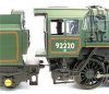
    The 9F I am scratch building, after acquiring a Bachmann model and looking at its short comings.

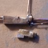
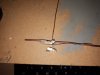
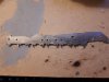
    Their attempt at the “plumber’s nightmare” shows how they failed to interpret the drawings they were using. Topside, they got the dimensions of the boiler feed pipes to the clack valves spot on, but beneath the cab these pipes are little more than handrail size wires. This is really odd when the two pipes should connect together. I’ve been building the bits to replace all of this and so far on the third (or 4th?) attempt at the exhaust steam injector. I have managed to break three whilst filing the solid brass at the thinness point. Soldering it back together would be a nightmare as I was getting down to low temp solder as I worked along; this would be very weak. The Mk4 shows promise, after a redesign. A few pictures attached. A friend who actually fired these for BR has given me an A3 size drawing to work from.

    2_ES6_1.jpg
    The Bachmann interpretation. It sort of has 2 live steam injectors

    the real thing

    Evening Star Auxilliary Steam Pipes The large size of this is impressive.

    http://www.fraserker.com/winson/britannia_pix/Britannia - Injector Right.jpg

    A much better view is on Britannia 7000

    http://www.fraserker.com/winson/britannia_pix/Britannia - Injector Right.jpg

    This site will show you all the details of almost every BR Standard fitting.

    Pictures of
    20200517_205309.jpg

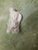
    The first one third on its way. Reject at bottom. The finished main body is only 9.5 x 3 mm so this is large.
     

    Attachments

    • 2_ES6_1.jpg
      2_ES6_1.jpg
      77.3 KB · Views: 6
    • 20200517_205309.jpg
      20200517_205309.jpg
      118.7 KB · Views: 6
    • 2_ES6_1.jpg
      2_ES6_1.jpg
      77.3 KB · Views: 6
    • 20200517_205318.jpg
      20200517_205318.jpg
      174 KB · Views: 7
    • 20200517_205209.jpg
      20200517_205209.jpg
      125 KB · Views: 6
    9F
  • Ken589

    Member
    I am really at producing components stage for this build, but here are a few holiday snaps

    20200517_205234.jpg

    1 pair nickel silver frames, and boiler with Pinochio smokebox.
    The nasty look on the edges is not my filing, but double sided tape. Awaiting arrival of steel flux so I can make a start on connecting rods, then on to horn block cut outs. The other side has the marks for the axle centres. Yes the bottom of the frames does need a tidy up to the spring hangers and horn block supports. and frames need the strengthening piece adding below firebox at narrowest point. Am planning to build the full longitudinal stretcher and cross stretchers too, if feeling mad enough. Drive will be via tender motor with universal joints.

    A true warts and all expose.

    The boiler and fire box. I’ve had great difficulty in blending the firebox to boiler at the angled joint. I fear my wooden former I used to bend the copper round was a fraction large. Think the boiler may just creep in diameter at this point. All corners are sharp as my radiusing became rather variable, hence the filler. Will make a suitable guide. The boiler and firebox are just three bits of metal, all ex-central heating pipework off-cuts. I learned the art of boiler filling here. (More pictures to come featuring the 4Fs)
    20200517_204552a.jpg
    Just to prove a splice can be made to fit and soldered in. The cracks along the splice are due to my dropping it, this explains the new smokebox too. Must remember next time to do it on carpet not concrete. Ow. The holes near firebox are shadow, really!
    Still new to this posting bit but will show Spam Can and 4Fs soon
    Stay safe - glad to say nothing yet here for me in our villages.
    Mark
     
    More news from Midford.
  • Ken589

    Member
    Many thanks for all your greetings.

    As I explained in my intro, this is my first really large layout and it’s a big learning curve.

    Like most people I started off by just building open top boards with a track base, assuming my plans would work at 12” to the foot scale. It didn’t work out too well. Things just didn’t look quite right.

    I took some time just letting the view of the track bed “sink in” along the full length of the room. I eventually saw that flattening the curve through the station to maximise the radius of the curves at the end of the room had resulted in the loss of the flow of tracks along the cliff edge by the platform. I’m afraid I didn’t take a photo to show this but below are the beginnings of the mk 1 track bed.

    Some very early pictures.
    20190709_095724.jpg
    Removing 12 feet or so track bed to realign it was a painful task. I really shouldn’t have screwed and glued every joint. Plus the new alignment meant recalculating the height for every riser. (A rise of 1mm per foot from datum means this post needs to be xyz. But because each baseboard end is resting on the previous one and stepped, I must subtract abc to get the correct answer. Stop check framework is really level. Forget answer. Try again.


    20190709_095811.jpg
    At least by the time I’d got to the fourth board (above) I was learning to make a basic frame and then add in the additional framework to support track and scenery, not just put a cross bearer in every foot or so. These always ended up in the wrong place or at the wrong angle. Sherwood Forest is probably quite heavy too.
    Just a little background to this week’s disturbances.

    My son’s Limpley Stoke to Camerton Branch is the most advanced track base so far (I’d promised he could run his trains soon) but as I laid the track under the viaduct it became clear I could not live with the curve I’d laid out. Demolition ensued, including a completed embankment, and a new track bed cut and installed, well sort of. The limit of deviation on the plans allowed for the changes, and the engineer was happy, but not so the landscaper faced with a 2ins thick plywood wall at the baseboard joint. Short of removing each baseboard in turn from the window end this joint is going to be a challenge for the demolition team. Yes, I did allow space to dismantle the boards but the gap is by the window 15ft away.

    20200526_152351.jpg
    I
    A tour starting with the branch line viaduct.


    20200526_152953.jpg
    Limpley Stoke branch viaduct at Midford. Awaiting brick work. Now crossing a duck pond and canal drainage dyke/sluice. The original was built to re
    cross Midford Brook further across the valley. To achieve this was far too difficult in my compressed space scenario, but viaducts are expensive so why was it built.


    20200526_153023.jpg
    The other side of the viaduct.

    Somerset Coal Canal centre, ice cream tub is Hope and Anchor pub. Marge is Toll Collector’s house.

    Note path of the sluice and line of pond. There is no lock between here and the Kennet and Avon Canal Junction and they must be able to drain it somewhere for maintenance, why not at Midford? Rising path is the tow path which crosses over the canal at the main road. A roving bridge. Walls to protect tow line still to be made. S&DJR viaduct in the background.

    See The Canal, Midford c.1904

    To diverge for a second, in spite of an almost total absence of pictures of the canal bridge, it is possible to get one today. see below.

    canal bridge 2009.png

    canl rd briddge2.png

    I am fairly certain this is the canal bridge today with the path sloping down to the canal at the post before the pub sign. It conforms in shape to other bridges on the canal. Google street views
    View of Midford looking north, c.1922
    shows how this scene should look and how it is now compressed. In reality the Limpley Stoke line went up the east side of the valley and the S&D up the west. There is however in Mike Arlett’s book, The Somerset and Dorset at Midford a map (p41) showing a proposal of 1902 by the North Somerset light railway to build a line following very nearly the path as built here. A really crazy scheme but it was proposed.


    Back to the viaducts.
     
    More from Midford 2
  • Ken589

    Member
    Back to the viaducts.


    20200526_152933.jpg
    Top is S&D Midford Viaduct. Centre is Limpley Stoke branch line and below that Midford Brook following its correct course. As can be seen it would look very wrong doubling back between the two railway lines. For this route the natural course would be under the next arch towards the station which lines up with the bridge under the road.

    When I first starting planning this area it all seemed a tortuous mess but on building it began to make sense. On the S&D viaduct the line changes from a 1:330 descent from the north to 1:60 ascent to the south. This happens precisely at the junction point in the middle of the viaduct.
    20200526_152933.jpg
    The big hole in the viaduct is to accommodate a point where the single line becomes double. The darker area on the branch line track bed shows where additional material has been added to meet the engineer’s new specification and the spike to the left is the old alignment.
    20200507_134336.jpg

    Point in situ and a couple of close-ups.

    20200507_134351.jpg
    20200507_134358.jpg

    Plywood base, templot plan, lace pins in predrilled holes in coffee stirrer sleepers. Very slight sanding needed to size the sleepers. It still wants a dust and a point locking mechanism. Large holes to screw it down. First time effort after previous pcb construction. Ancient but very good ECM point motor underneath, motor and screw thread drive, totally reliable DPDT switch. 6th layout usage? Construction enabled bench build and testing. Having done this a novel way I can’t understand why the P4 original builders used rivets. I know how my remaining three visible points will be built. Oops forgot there’s two catch points as well.

    I've diverged but a bit more on points and signals before back to the layout proper.
    20200527_162752.jpg
    Point and signal control. The prototype lever for Midford signal box frame. The control of points and signals is going to be electrical but will all be fully interlocked both mechanically and electrically using a 16 lever frame. Midford box takes a whole chapter in Mike Arlett’s book to explain its working. Suffice it to say there were detectors on nearly all the signals and some track sections that locked parts of the box electrically as well as the normal frame locking. I will try to sort all this out into a practical working solution, but at the moment only the slide bars and nibs are worked out for the mechanical locks and there matters have rested.
    Has anyone built a small Whitaker tablet machine? I want something to dispense tablets!
    Amazing how file marks show on polished steel. This little chappie needs an extension to his bottom (legs?) but was made from a two inch panel pin, a gas ring on the BBQ and a large hammer. Brass bit for lever which does work. All 16 levers made, only one latch so far. Ever wished for a few more hours?

    20200526_153152.jpg

    A view from Midford signal box down the S&D Viaduct and the Twinhoe road. The viaduct (still about 2/3 of it to build this side) shows the gradient change quite nicely. In the distance is the branch line and just visible its tunnel mouth.
    There is a very nasty bump in the road just after the canal bridge, and beyond it is where the river bridge will be. The spike in the field is to remind me to dig a trench for the brook. The road can then be seen ascending towards the door in the far distance where it turns un-prototypically left. The real road bears right. The transition of the embankment to a deep cutting is not quite correct yet on the “viewing side” but I need to build across the doorway to clarify this. The depth of the cutting is indicated by the road in mid air.
    20200526_152326.jpg

    The embankment south of the viaduct and some scenery framework appearing.
    Twinhoe road is hanging in space by the blue container, and hints at deepish cutting. This has a large retaining wall and yet more brickwork stonework.

    To the right can be seen an angled ply piece for the foundations of one of the two 3 storey houses alongside the road. Access to the 2nd is being worked out with various options shown in sloping wood. The branch line now goes between them. Hopefully the extra 2" or so gained by moving the track my help me get my head around this. Would a farmers's "accommodation crossing" (level) have been allowed?
    My instinct says no but maybe someone can advise.

    The cutting on the "viewing side" should begin where a join can be seen in the underlying polystyrene tiles nearest the door. However this may be adjusted so it gives the best appearance of the trains vanishing briefly. I need to build the next bit first, but this will be built last.
    The doorway "bridge" will be interesting and I plan to have a section that pivots on substantial door hinges. The “free side” will have a wheel under it to bear some of the weight. This opening will have to carry 8 tracks across it, all at different levels and all with gradients. A lifting flap is just not going to work! My theory is a door always fits exactly into its frame and door lock and latch alignment works perfectly, usually for years without need for any adjustment. An extreme example, but one I used every Sunday, is the Church safe. It always shuts and locks and is even airtight. Providing the woodwork is completely rigid on all sides.... Here the legs are 2" x 2" and braced by thick plywood corner triangles.
     
    More developments on the Camerton branch line.
  • Ken589

    Member
    23:30 was late enough: the next episode follows.
    Rock castings, part 2:
    Peeling off the foil from the first castings I found I was left with some large pieces of foil and quite a few smaller ones.
    Thinking there is nothing to lose, I packed various small bits, jigsaw wise into the bed of saw dust.
    i was very pleasantly surprised with the results.
    The sawdust marks are the divisions where the mould leaked at the joins and the small bits of foil show where the the method trapped foil a the joints. A small amount of scraping soon cleared this up. 20210125_164404.jpg
    I did find that it was not worth trying to get a third casting out of the foil. Pieces were now getting very thin as well as badly torn.
    My first castings I cleaned up all the overflow around the edges with a razor saw and sand paper. This produced nice clean sides that very few rocks actually have.
    Now that I had got used to making small scraping marks with a knife to clean the joins I set out to see what could be done with some of the bulges, such as that centre right above.
    I found that making small stabs with a knife at about a 70deg angle to the surface removed very small chips and that by repeating a stucco surface would result. By using the cast portion as a reference, the bulges were attacked to slowly produce high and low points and continue the shape of the casting. The learning was interesting as it is very easy to exaggerate the different levels; it all looks fine when only seeing the 2- 3 cm of the work area but when seen as a whole it was not at all what I was seeking.

    20210129_203551a.jpg
    Sorry this is out of focus and cropped off a big picture, but it is the first of my casting failures I attempted to re-carve in situ.
    I think this is the second attempt.
    Careful examination shows the rocks are sticking out over 12 - 18" (scale) from each other and the carved lines, representing the fault lines and layers in the rock are all in the wrong planes.
    A vigorous scraping down and another variant emerged.
    20210130_230803b.jpg
    This gave me enough courage to start to fill in some of the blank areas that I had not got castings for.
    20210129_203728.jpg
    An area plastered up ready for carving.
    20210130_230417.jpg
    The result some time later. It is not as good as the casting to the right but the eye apparently looks for detail at the ends of a run of similar scenes rather than the middle. Place your most detailed wagons/coaches at the ends of rakes/trains and tri-ang in between. Run the train and see if your friends spot what you have done on a video.

    A final touch on rock castings. Do you throw anything away whilst you are working?
    I try to keep the debris field down by putting plaster lumps in a box and chippings in another.
    On Friday I picked up almost the last lump on my workbench and saw I'd had a visitor.
    20210129_204309.jpg
    A cowled figure or is it?
    20210130_212009.jpg
    I think the sharp lines are knife marks but what it fell off I haven't a clue, or why I was attacking it.
     

    Attachments

    • 20210131_221910.jpg
      20210131_221910.jpg
      76.7 KB · Views: 0
    More developments on the Camerton branch line 2
  • Ken589

    Member
    Couldn't up load my final picture.
    20210131_221910.jpg
    An angel with one wing missing?
    There is even a fracture mark to show where the wing fell off..
    (Remember I'm a vicar..)
    Anyway Midford Goods Yard now has a guardian angel . 20210130_230358.jpg
     
    Top