You are using an out of date browser. It may not display this or other websites correctly.
You should upgrade or use an alternative browser.
You should upgrade or use an alternative browser.
7mm Heyside: 7mm L&Y, late 50s/early 60s
- Thread starter Dikitriki
- Start date
Jordan or Plymouth Mad
Mid-Western Thunderer
Heyside: 7mm L&Y, late 50s/early 60s
Is there a "Complete CV's Guide" anywhere, that's also written in plain english?? I hear lots of references to "CV Tables" but it's all just numbers in the air to me, and often it seems a lot of guesswork is needed, especially when trying to get motors to run at their best... even the NCE manual seems to have phrases such as "try a value of 4 for XYZ #CV".
How on earth you get locos to match performance with each other (even of the same make, if they don't quite run together in DC !!) is currently beyond me - it certainly doesn't seem as simple as some make it sound, and these things always seem to involve having to buy extra kit (such as Decoder Pro/Sprog etc)...
Having used DCC on other people's layouts I can certainly see the advantages of it; mainly the independant train control (sound is okay but can get on the nerves, and loco lights show up the lack of lights elsewhere on the layout!!), but even at one operating session I was at, I saw a loco somehow just inexplicably reset itself right back to "factory defaults" with an Address of '3' whilst being run. :
:") :vista:
:vista:
I'm with dikitriki on this... I'm finding DCC far more complex and frustrating than the 'plug'n'play' heaven it is often portrayed as, and I'm only testing HO locos on a short piece of track yet...Dog Star said:Quagmire comes to mind...
...my impression is that Mr. ABC understands what needs to be done to the CV tables to get the best out of his motor/bearbox combinations.
Is there a "Complete CV's Guide" anywhere, that's also written in plain english?? I hear lots of references to "CV Tables" but it's all just numbers in the air to me, and often it seems a lot of guesswork is needed, especially when trying to get motors to run at their best... even the NCE manual seems to have phrases such as "try a value of 4 for XYZ #CV".
How on earth you get locos to match performance with each other (even of the same make, if they don't quite run together in DC !!) is currently beyond me - it certainly doesn't seem as simple as some make it sound, and these things always seem to involve having to buy extra kit (such as Decoder Pro/Sprog etc)...
Having used DCC on other people's layouts I can certainly see the advantages of it; mainly the independant train control (sound is okay but can get on the nerves, and loco lights show up the lack of lights elsewhere on the layout!!), but even at one operating session I was at, I saw a loco somehow just inexplicably reset itself right back to "factory defaults" with an Address of '3' whilst being run.
: :vista:Steph Dale
Western Thunderer
Heyside: 7mm L&Y, late 50s/early 60s
Blimey, what tails of woe...
Richard, I must admit I'm perplexed by your fun with 10001, but my money is still on a mucky signal and that for the price of a few pence the snubber(s) would be worth a try.
Specific points have been raised through the last few hours of postings. So let's try a few quick pointers:
Richard, Brian at ABC may not be able to help you with the 2P. He certainly knows a lot of stuff about setting up his gearboxes with DCC or otherwise, but I know he's not terribly familiar with Lenz stuff. He does know ESU quite well though and so may be able to offer some help with your model of 10001. On 10001 check CV29 before you go much further, the value for ESU or Lenz decoders should be 2 if you're using short addresses, 34 if you're using long; this will set them to digital only operation. And no - I don't think it's a faulty chip. Silicon tends to suffer gross degradation or not at all. Might be worth a reset to check all's well before setting CV29 and re-allocating the address: enter 8 into CV8 and then power cycle the decoder to reset. Just wondering - have you had any problems programming this decoder?
Jordan, I use a SPROG and JMRI DecoderPro for programming because my (Lenz) system doesn't come as standard with a PC interface. The software is free and can be used with systems other than the SPROG; although it's a darned handy combination. Before I had the SPROG all my locos were programmed the hard way, using a programming track. In order to get the consistency you desire it became a case of storing CVs in spreadsheets. Still manual programming though. You could use DecoderPro to do this for you I think, if you fancied that idea. It would give you the option of storing the data either descriptively or as CV values. I know that some CVs are standardised by the NMRA standard, but some are not and all seem to be open to some interpretation. So the only way to tell what CVs do and/or how they behave is to use the decoder manual. The setting of the drive CVs is by it's very nature experimental, most of the decoders I use include a little routine for optimisation which takes a little going through but the results are worthwhile IMHO.
I have to say that while I've been an enthusiastic user of DCC for many years, it's not for everyone. I would never advocate DCC for all. You've got to be comfortable working from manuals (and many in our hobby take some perverse delight in saying they never use kit instructions!), be comfortable with digital technologies and prepared to spend a little time. The results for me have been fantastic, but I recognise some of the features and the effort it took to get here. Just for some examples; better decoders can drive motors below their stall speed, so the scared cat running of a couple of locos has been tamed without needing comprehensive rebuilding (yep - even Lima 00/HO ringfields!). The use of on-board energy stores such as Lenz Power1 has given me 100% reliable running of even very small 0-4-0 locos. I can carry a complete control panel in one hand. With carefull setting up of the drive CVs each of my locos has a custom controller on board which is tailored to that specific motor and model, etc, etc. I should also add that despite some very strange wiring and large layouts I've not personally come across many of the problems described in this thread either!
More on my findings here, for those that are still interested: http://euram-online.co.uk/dcc/dcc.htm much of it is now out of date, but the theory still seems to hold.
I think that's it for now although much more could and has been said.
I hope we get the layout sorted Richard, and soon. I know how frustrating it can be; even if the last time I had a similar melt down it was with an analogue layout... :scratch:
Steph
Jordan or Plymouth Mad
Mid-Western Thunderer
Heyside: 7mm L&Y, late 50s/early 60s
:-[
I was given a load of HO stuff, a couple of the locos have DCC chips fitted; sometimes the NCE Powercab can read them, other times it seems it can't; but hey-ho.. if it can, it flags up a number which apparently tells you what make the chip is; I ought to do more Interweb research and find out what they are!! The Bachmann DCC-fitted loco came cheap off flea-bay, the only instructions being a note in the box saying it was default address three... This one has responded to re-programming - I can here the chip 'click' (like laptops do) when values are changed; trouble is I still really don't know what I'm doing properly. The 'mystery' chips don't seem to be responding at all, as yet.
I haven't really had time to have a really in-depth go at getting the hang of this stuff, that's part of the trouble.
Sorry if my posts are hi-jacking this thread a bit.... :-[
Ah, now there's a problem, as I don't have any decoder manuals :Steph Dale said:...the only way to tell what CVs do and/or how they behave is to use the decoder manual. ...
:-[I was given a load of HO stuff, a couple of the locos have DCC chips fitted; sometimes the NCE Powercab can read them, other times it seems it can't; but hey-ho.. if it can, it flags up a number which apparently tells you what make the chip is; I ought to do more Interweb research and find out what they are!! The Bachmann DCC-fitted loco came cheap off flea-bay, the only instructions being a note in the box saying it was default address three... This one has responded to re-programming - I can here the chip 'click' (like laptops do) when values are changed; trouble is I still really don't know what I'm doing properly. The 'mystery' chips don't seem to be responding at all, as yet.
I haven't really had time to have a really in-depth go at getting the hang of this stuff, that's part of the trouble.
Sorry if my posts are hi-jacking this thread a bit.... :-[
Dikitriki
Flying Squad
Heyside: 7mm L&Y, late 50s/early 60s
Looks like we're in this together Jordan!
Steph: about the snubbers.
Do you need one per circuit/power district?
Do they go at the end of the circuit where the bus terminates?
Can you point me to exactly what I want and a supplier please. I don't have confidence I would end up with the right thing!
Thanks
For those who want some proper modelling action, I have found a good use for P4 sleepers - decking for 7mm scale signal gantries ;D Absolutely perfect. I have cut 81 lengths of copperclad and soldered them to the brass cross members. Yes, I counted them. How sad is that.
I shall attach the truss rods and smoke deflectors then the dolls can go in.
Cheers
Richard
Steph Dale
Western Thunderer
Heyside: 7mm L&Y, late 50s/early 60s
Richard,
The answer to your first question is a conditional 'yes'. I thought you only had one booster? In which case only one 'power district'. Are they switched? What switches have you used if so. 'Cos they could be the cause of all your problems...
Question 2, Yep, that's where I'd start with them and see what happens.
Question 3, Maplin http://www.maplin.co.uk/ components will be fine: Resistor 100 Ohm, 0.6w would be item M100R at 24p each. Capacitor 0.1uF, 50v would be item BX03D at 31p each. These are pretty expensive prices, but you'll only need a few of each, not thousands.
That should get you started...")
Steph
Dikitriki said:Steph: about the snubbers.
Do you need one per circuit/power district?
Do they go at the end of the circuit where the bus terminates?
Can you point me to exactly what I want and a supplier please. I don't have confidence I would end up with the right thing!
Thanks
Richard
Richard,
The answer to your first question is a conditional 'yes'. I thought you only had one booster? In which case only one 'power district'. Are they switched? What switches have you used if so. 'Cos they could be the cause of all your problems...
Question 2, Yep, that's where I'd start with them and see what happens.
Question 3, Maplin http://www.maplin.co.uk/ components will be fine: Resistor 100 Ohm, 0.6w would be item M100R at 24p each. Capacitor 0.1uF, 50v would be item BX03D at 31p each. These are pretty expensive prices, but you'll only need a few of each, not thousands.
That should get you started...
Steph
Dikitriki
Flying Squad
Heyside: 7mm L&Y, late 50s/early 60s
Hi Steph
Thank you for that.
Perhaps I am using the terms incorrectly - it wouldn't be surprising.
The layout is divided into 4 separate wiring circuits, up main, down main, branch and yard. the reasoning being that if we had any problems with one circuit, the other 3 could remain running, rather than losing the whole layout. I called these the power districts. All of these 4 circuits go through individual short circuit protectors and thence to the controller. The booster, as I understand it, was to take the NCE system from a 5 amp system to a 10 amp system, and there is just one from which 2 wires go to the short circuit boards. They are not switched.
Perhaps I am using the term booster incorrectly. I an using a Power Pro CS02 and a Power Pro PB110, nothing else.
Just looked at the manual, I am right, PB110 is described as a booster.
Richard
Steph Dale said:The answer to your first question is a conditional 'yes'. I thought you only had one booster? In which case only one 'power district'. Are they switched? What switches have you used if so. 'Cos they could be the cause of all your problems...
Hi Steph
Thank you for that.
Perhaps I am using the terms incorrectly - it wouldn't be surprising.
The layout is divided into 4 separate wiring circuits, up main, down main, branch and yard. the reasoning being that if we had any problems with one circuit, the other 3 could remain running, rather than losing the whole layout. I called these the power districts. All of these 4 circuits go through individual short circuit protectors and thence to the controller. The booster, as I understand it, was to take the NCE system from a 5 amp system to a 10 amp system, and there is just one from which 2 wires go to the short circuit boards. They are not switched.
Perhaps I am using the term booster incorrectly. I an using a Power Pro CS02 and a Power Pro PB110, nothing else.
Just looked at the manual, I am right, PB110 is described as a booster.
Richard
Steph Dale
Western Thunderer
Heyside: 7mm L&Y, late 50s/early 60s
Richard, that's all starting to make some sense. Apart from the bit about the 'Short Circuit Protector' Is this an NCE item too? Can you provide a reference, please - I'd like to know what they're doing. The systems I'm familiar with all have short circuit protection on the booster or command station.
My concern is because an intermittent or low-rated (i.e. damaged) connection can cause disruption of the signal on the bus. I think that's the problem so it's going to help me to know what else is connected to the circuit. The truth is that potentially all connectors, cables, (dry)solder joints fall into this category one way or another. Which reminds me - what connectors are you using on the layout?
Steph.
Dikitriki said:Hi Steph
Thank you for that.
Perhaps I am using the terms incorrectly - it wouldn't be surprising.
The layout is divided into 4 separate wiring circuits, up main, down main, branch and yard. the reasoning being that if we had any problems with one circuit, the other 3 could remain running, rather than losing the whole layout. I called these the power districts. All of these 4 circuits go through individual short circuit protectors and thence to the controller. The booster, as I understand it, was to take the NCE system from a 5 amp system to a 10 amp system, and there is just one from which 2 wires go to the short circuit boards. They are not switched.
Perhaps I am using the term booster incorrectly. I an using a Power Pro CS02 and a Power Pro PB110, nothing else.
Just looked at the manual, I am right, PB110 is described as a booster.
Richard
Richard, that's all starting to make some sense. Apart from the bit about the 'Short Circuit Protector' Is this an NCE item too? Can you provide a reference, please - I'd like to know what they're doing. The systems I'm familiar with all have short circuit protection on the booster or command station.
My concern is because an intermittent or low-rated (i.e. damaged) connection can cause disruption of the signal on the bus. I think that's the problem so it's going to help me to know what else is connected to the circuit. The truth is that potentially all connectors, cables, (dry)solder joints fall into this category one way or another. Which reminds me - what connectors are you using on the layout?
Steph.
Dikitriki
Flying Squad
Heyside: 7mm L&Y, late 50s/early 60s
Steph
The short circuit protector is this.
http://www.digitrains.co.uk/ecommerce/d ... psx-4.aspx
The inter-baseboard connectors I will have to photograph tomorrow, they came from DCC supplies as heavy duty connectors, each pin being 9 amp rated I think.
Richard
Steph
The short circuit protector is this.
http://www.digitrains.co.uk/ecommerce/d ... psx-4.aspx
The inter-baseboard connectors I will have to photograph tomorrow, they came from DCC supplies as heavy duty connectors, each pin being 9 amp rated I think.
Richard
Dikitriki
Flying Squad
Heyside: 7mm L&Y, late 50s/early 60s
Hi
I came away from Kettering very enthused as always. I had a good chat with Steph on DCC matters, and once I fit the snubbers I shall report back. I'll also clean the track and wheels come to think of it.
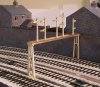
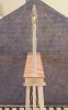
But back to real modelling, I have fitted the dolls to the gantry and tried it for size. Not the scale of mikemeg's Scarborough efforts, but the first time I have attempted any signalling, and I shall unashamedly pinch some of his ideas later.
I have tried very hard to keep everything upright and in line, and here is the current state of play...
Hi
I came away from Kettering very enthused as always. I had a good chat with Steph on DCC matters, and once I fit the snubbers I shall report back. I'll also clean the track and wheels come to think of it.
But back to real modelling, I have fitted the dolls to the gantry and tried it for size. Not the scale of mikemeg's Scarborough efforts, but the first time I have attempted any signalling, and I shall unashamedly pinch some of his ideas later.
I have tried very hard to keep everything upright and in line, and here is the current state of play...
Attachments


Phill Dyson
Western Thunderer
Heyside: 7mm L&Y, late 50s/early 60s
Signal gantry looks great.......as does the ballasting
Phill :wave:
Signal gantry looks great.......as does the ballasting
Phill :wave:
Rob Pulham
Western Thunderer
Heyside: 7mm L&Y, late 50s/early 60s
That look superb Richard, what did you use for the posts under the deck?
That look superb Richard, what did you use for the posts under the deck?
Dikitriki
Flying Squad
Heyside: 7mm L&Y, late 50s/early 60s
Thanks for the comments guys. The design is based on L&Y gantries around Manchester and Blackpool, the assumption being that the gantries remained while the hardware was upgraded to LMS.
Rob, Scale Signal Supplies supply tapered wooden posts for square signals. I sorted through his stock to pick the longest, had 6, with the top part becoming the dolls and the lower part becoming the long legs of the frame. I still had to piece 3 of the 4 legs as you can see in the photos. The rest of the wood came from my stock of quality close-grained wood that I had retained from my earlier musical instrument making days. This takes more working, but can be filed more readily and is much less prone to splitting and other damage. It was drilled and pinned (with a cocktail stick) on a template I drew up, with the rest of the components just superglued in place. At the bottom of the legs, there is a brass plate, and this is soldered to brass rods let into the bottom of the legs. All-in-all, a very strong structure, despite the mixed media approach.
The most difficult part was working out how to join the 4 transverse girders to the Wooden 'A' frame legs. In the end I soldered pins to the girders, and superglued them into holes in the supports. This was still very flimsy, until the decking was put on, and I finally inserted small wooden blocks to mate the sides of the girders with the top of the supports. When the spandrels are glued on (they are being cast for me by Scale Signal Supplies) I think it will be very solid.
Richard
Rob Pulham said:That look superb Richard, what did you use for the posts under the deck?
Thanks for the comments guys. The design is based on L&Y gantries around Manchester and Blackpool, the assumption being that the gantries remained while the hardware was upgraded to LMS.
Rob, Scale Signal Supplies supply tapered wooden posts for square signals. I sorted through his stock to pick the longest, had 6, with the top part becoming the dolls and the lower part becoming the long legs of the frame. I still had to piece 3 of the 4 legs as you can see in the photos. The rest of the wood came from my stock of quality close-grained wood that I had retained from my earlier musical instrument making days. This takes more working, but can be filed more readily and is much less prone to splitting and other damage. It was drilled and pinned (with a cocktail stick) on a template I drew up, with the rest of the components just superglued in place. At the bottom of the legs, there is a brass plate, and this is soldered to brass rods let into the bottom of the legs. All-in-all, a very strong structure, despite the mixed media approach.
The most difficult part was working out how to join the 4 transverse girders to the Wooden 'A' frame legs. In the end I soldered pins to the girders, and superglued them into holes in the supports. This was still very flimsy, until the decking was put on, and I finally inserted small wooden blocks to mate the sides of the girders with the top of the supports. When the spandrels are glued on (they are being cast for me by Scale Signal Supplies) I think it will be very solid.
Richard
Jordan or Plymouth Mad
Mid-Western Thunderer
Heyside: 7mm L&Y, late 50s/early 60s
I must admit that's something I would never have thought of... but boy I bet it'd stick out if the signals weren't all vertical!! Well done!!Dikitriki said:I have tried very hard to keep everything upright and in line, and here is the current state of play...
)")
Dikitriki
Flying Squad
Heyside: 7mm L&Y, late 50s/early 60s
Hi
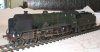
The Heyside group are all working frantically to ensure that we have the right motive power and rolling stock to hit the ground running for the Manchester exhibition, and while most steam locos will be black, just a couple will be green. Here's one such, just finished, and rostered for one of the semi-fasts. It is an Oldham Loop loco, built by Roger.
[attachimg=1]
I shall get some layout photos later, but worth showing now I think.
Richard
Hi
The Heyside group are all working frantically to ensure that we have the right motive power and rolling stock to hit the ground running for the Manchester exhibition, and while most steam locos will be black, just a couple will be green. Here's one such, just finished, and rostered for one of the semi-fasts. It is an Oldham Loop loco, built by Roger.
[attachimg=1]
I shall get some layout photos later, but worth showing now I think.
Richard