Horwich 18 inch gauge engines

michael mott

Western Thunderer
I want to keep the Drawing thread and the loco builds separate, so my interest in the little shunting engines began many moons ago (2005) when I converted a Bachmann Percy into a rough representation of one of the Horwich shunting locos I called it Mercury.

I used the nominal scale of 1/24 for the build and of course the track gauge was 16.5mm.

Taking Percy apart.

DCP09026x1024.jpg

Blocking up the loco with some Rigid PVC, and a turned brass dome, and chimney, this was the final version of plastic bits.

DCP09064x1024.jpg

Placing styrene wrapper with embossed rivet detail.

DCP09451x1024.jpg

A lick of paint over the plastic and the wheels have had styrene discs glued on .

DCP09742x1024.jpg

Fancy brass bits added to the loco to spiff it up a bit, the nameplates are embossed annealed .003" brass made by using a 9H pencil suitably sharpened so as not to puncture the soft sheet. the sheet was placed on some archival quality matt board and I practiced before hand writing in reverse by printing it up and tracing over it enough times to get a decent enough result before working on the actual brass one.

IMG_0600x1024.jpg

Bertrand had asked for some coal for the firebox, so I had to oblige him.

IMG_0620x1024.jpg

Bertrand was rather fussy always polishing and dusting as the work progressed.

IMG_0829x1024.jpg

Beginnings of the brake set up.

IMG_0906x1024.jpg

Drivers View.

IMG_0911x1024.jpg

It is a charming little loco and one that makes me smile when i think about the fun I had building it.

Next I purchased the drawings from the NRM and started to build a live steam version that would run on 45mm gauge track, so in order for the 45mm to represent 18 inches I decided to begin the model in 30mm to the foot scale, The dreaded conflation of different measuring systems. I mostly used Corel Draw 11 so that I could trace the digital copies I had purchased from NRM for the model and set it up to the 30mm scale. My Autocad Lt 2000 cannot import the drawings without crashing.

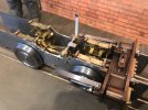
The chassis to this point was a few months with of work, with a number of part made and remade.

IMG_7375x1024.jpg

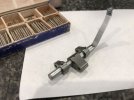
The plan was to use a large copper T for the boiler.

IMG_7377x1024.jpg

IMG_7378x1024.jpg

I was relying on the designs of Harvey Watkins for the boiler design and wanted to fire the loco with coal.

IMG_7381x1024.jpg

The wheel bearings are split as per the full size practice.

Capture7417.JPG

Capture7420.JPG

Capturex7419.JPG

That's it for now, This is leading up to the new build which will be 1/16 scale or 3/4 inch to the foot . which will give a gauge of 1 1/8th inches.

Michael
 

michael mott

Western Thunderer
back to the big Horwich.
I made the cylinder block as a solid block at first but was not happy with the direction it was going.
IMG_7723x1024.jpg

IMG_7725x1024.jpg

IMG_7737x800.jpg
So took a different path and soldered one up using a high temp soft solder.

IMG_7934x800.jpg

IMG_7971.JPG

IMG_8012x1024.jpg

The lapping of the ports within the central steam chest was the hard part.

IMG_8055x1024.jpg

IMG_8070x1024.jpg
Fitted into the frames thinking about the flanges to bolt to the frames.
IMG_7877zx1024.jpg

Finally all the parts of the cylinder assembly soldered up and cleaned the copper colour came from the pickle solution.

IMG_8024x1024.jpg

The hornblocks were made from the NRM drawings out of some bronze fiddly devils to machine. springs were made and added.


IMG_8118x1024.jpg

The studs and cover plate for the steam chest fitted.

IMG_8185x1024.jpg

Enough pictures for today, off to file up the frames on the 3/4 inch scale loco.

Michael
 

michael mott

Western Thunderer
The next Items to get tackled were the eccentrics and they proved to be as fiddly as anything else.

I used a scrap of bronze threaded valve stem to form the blanks. after parting off some discs these were split with the jewelers saw and sweated back together for shaping and drilling.
IMG_8224x1024.jpg

IMG_8227x1024.jpg

IMG_8260x1024.jpg

After all the preliminary shaping they were un-soldered for further clean up.

IMG_8293x1024.jpg

A lot of work went into the arms and these ended up being made twice.

IMG_8480x1024.jpg
The new set on the left.
IMG_8485x1024.jpg

The discs for the Axles were machined out of some free machining steel.

IMG_8261x1024.jpg


IMG_8274x1024.jpg


IMG_8277x1024.jpg

The Allen valve gear lifting arm followed the arms were pinned with watchmaking taper pins. The brackets to hold the arm are different from each other one being a solid bracket and the end of the shaft slots into the hole, and the end that is bent is split to enable it to be extracted.

IMG_8420x1024.jpg


IMG_8398x1024.jpg

This is basically how far along this model is so far. a lot to still sort out, when i get back to it.

On the 3/4 inch scale model which will be electrically powered , I am thinking that the best place to fit the motor will be in the area that is occupied by the central steam chest., and I will add some plunger type pick ups at the end closest to the cylinders and position them low on the frames to hide them from view. I am hoping this will keep all the connections short and tidy.

Which brings me up to date on the new loco. This build will obviously be concurrent with the Cad Drawings and will be of a more simple construction and a lot of the areas that cannot be seen will be simplified.

The frames at 3/4 inch scale needed to be .047" thick I was able to get some .040" 1/2 hard brass sheet so that is what the frames are cut from I printed the frames drawing on large label sheet and stuck it onto a couple of strips of brass that were glued together with some CA glue. the used the jewelers saw to cut out the basic shape. I did initially think about drilling all the holes then realized that it was not needed for this model.

IMG_5131x1024.jpg

I thought I was being clever by resizing a set of steel wheels I had made for a small Harvey Watkins designed loco but have decided not to pursue it in favour of these locos. and then botched them by machining away the central boss area. Oh well I am sure they can find a use somewhere else. The frames have not yet been cleaned up in this picture.

IMG_5125x1024.jpg
Here is a shot of the new wheels the holes for the coupling rod pins still need to be drilled also one side set will need to be insulated.

IMG_0811x1024.jpg

Michael
 

Attachments

  • IMG_8420x1024.jpg
    IMG_8420x1024.jpg
    87.7 KB · Views: 2
  • IMG_8398x1024.jpg
    IMG_8398x1024.jpg
    126.8 KB · Views: 4

Peter Insole

Western Thunderer
Lovely stuff Michael, and good to see progress on the new model!

Sorry to be a PITA, but do check those "centre bosses" in the replacement wheelsets - they look a bit small to my eyes! Don't forget that the crankpins need to fit comfortably on them, and not end up too close to the outer edges?

horwichwren 7 SLS visit 15th August 1931.jpg

It is a crabby image, but it does just about show the proportions of a wheel with (nearly) fresh tyres, giving the full external diameter of a new wheel.

You might be able to measure and obtain a reasonable scale from the computer screen along a single horizontal line from the centre?

Regards,

Pete.
 

michael mott

Western Thunderer
Pete, thanks I shall double check the wheels. After all what’s another set of wheels going to cost other than time and material

Michael
 

Peter Insole

Western Thunderer
Oh dear, please accept my apologies to you again Michael! I am perhaps a little too close to the subject to be able to see objectively?!

I have been willing to accept various compromises on my own loco after all is said and done!!

Pete.
 

michael mott

Western Thunderer
Oh dear, please accept my apologies to you again Michael! I am perhaps a little too close to the subject to be able to see objectively?!

I have been willing to accept various compromises on my own loco after all is said and done!!

Pete.
No worries Pete these things happen, going through the same thing myself with the V2 van brake gear. I have revisited the model and the drawings here is my version of the wheels and Horn-blocks from the NRM drawings.
wheel detail x 1024.jpg

Excellent work, how do you keep everything sparkling clean?

Mike
Thanks Mike. I cannot keep things clean its an illusion, I go through bouts of "I have just got to clean this mess up" usually takes half a day.

The loco frames are now filed up and given a rub down with some 320 wet and dry. I am currently doing some drawings of various motor mechanisms that I have collected over the years from 00 and H0 locos I want to set the motor as close as I can within the cylinder area so that I can still add most of the motion because it is easily seen. The circular brass bearing were on the axles, and they are not part of the loco, I will make the proper ones to fit within the horn-blocks once they are fitted.

IMG_0819x1024.jpg

A comparison with some Peco O gauge track, I am going to use some code 215 and spike it down to wood sleepers. Also I am going to try to make some cast track that was used at Crewe and Horwich, but that is later.

IMG_0813x1024.jpg
I turned us a couple of quick gauges and flied a flat to stamp in the gauge.

capture 0822.jpg

Michael
 

michael mott

Western Thunderer
Nothing like a Sunday morning rethink
I was having a mind block trying to sort out the big round motor in the boiler and access concerns not to mention that I kept spilling the gears all over the bench trying to put it all together. It was not a good idea I realized, the big hand in the sky was trying to tell me something.

Went back to version 2 with a small Bachmann motor from a Percy loco that had been modified by removing all the eyeball moving mechanism parts.
Screenshot 2022-10-09 111433.jpg

Screenshot 2022-10-09 111138.jpg

The key was realizing I could thin down the width of the Printer gear that fits snug on the axle teeth to engage with the pinion in the Bachmann motor. Set up a test in the third hand

IMG_5138x1024.jpg

A crude mesh to test principle

capture 5135.jpg

Power on ..... whirr... pleased it will work.
capture 5137.jpg

Its a 5 pole motor and since this loco was not designed to pull a rake of 7 coaches anyway I think the power will be adequate for puttering around the works.

Michael
 

michael mott

Western Thunderer
Need to get the wheels in so have done some preliminary work on the horn-blocks. I am keeping them more simple than on the larger loco.
I plonked a boiler barrel onto the larger loco and checked how much could be seen, precious little, as confirmed by Pete earlier.

I also have drilled out the holes on the end plates.
first a clean up of the 1x1 slabs cut off a bit of bar stock.

IMG_5149x1024.jpg

some shaping to get the bearing surface set to slide into the frames. the depth is .015"
IMG_5155x1024.jpg

a snug fit

IMG_5157x1024.jpg

cutting the opening for the bearings, afte the two horizontal cuts the waste was cross cut with the jewelers saw.


IMG_5160x1024.jpg

Holes are tapped for some 0x80 screws to hold the keeper plates on.

IMG_5164x1024.jpg

next up the bearings, I think i will do them as split similar to the bigger ones.

Michael
 

michael mott

Western Thunderer
I have decide to keep things simple and will press the wheels onto the axles after the insulation bushes and the crank pins have been installed.
The axles revolve freely in the bearings and the bearings slide freely in the soldered up hornblocks.

IMG_5166x1024.jpg

IMG_5168x1024.jpg

IMG_5173x1024.jpg

I ran the motor on 8 AA batteries for an hour this afternoon the batteries were not fully charged and the voltage dropped from 5.76v to 5.60v over the hour, these were 2300ah batteries tomorrow I will see how AAA batteries hold up.

Michael
 

Simon

Flying Squad
Inspiring work, for me its especially your cutting out of the connecting rods from steel with your piercing saw, as I have a rather nice T9 with rather crude rods and a piercing saw....

So nice to see things being made and problems being pondered and solved.

Simon
 
Top