4mm Lynton & Lynmouth - 4mm scale, 8mm gauge.

Making a splash.
  • Tim Watson

    Western Thunderer

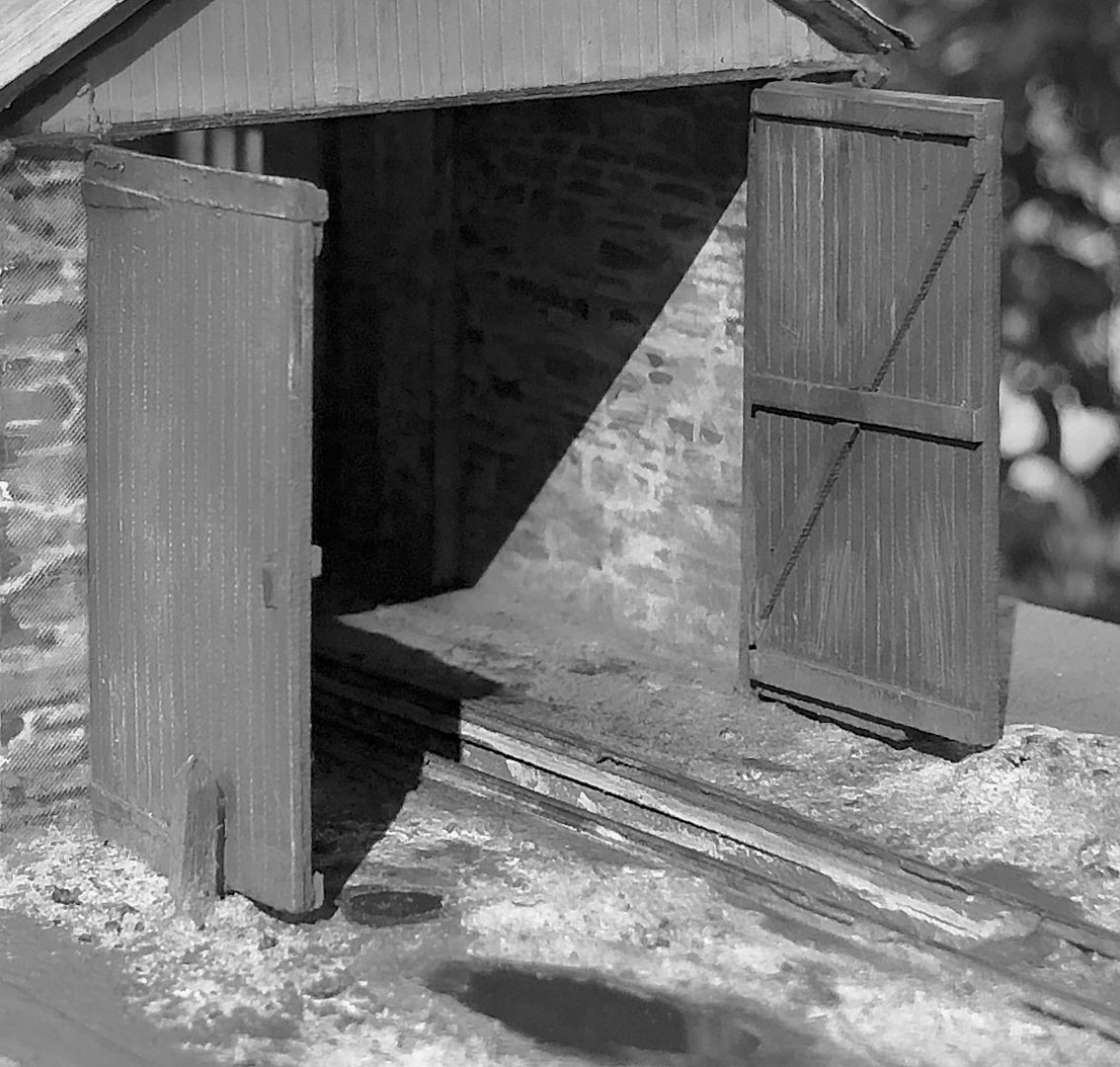
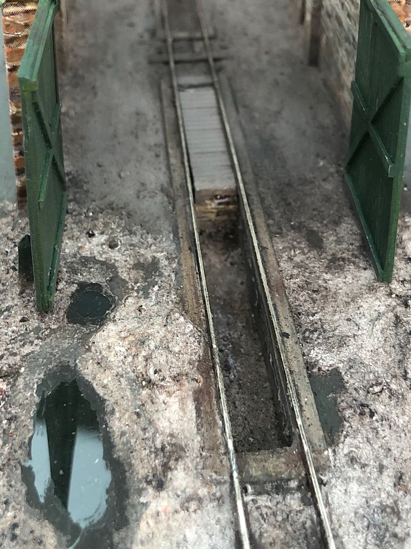
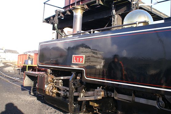
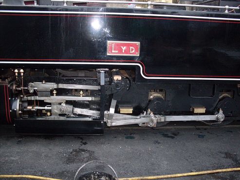
    I have cropped and enlarged this interesting picture of the Barnstable-end doors at Lynton. The ash had been shovelled out of the ash pit, but a leaking hose pipe has evidently made a couple of puddles - something well worth simulating...

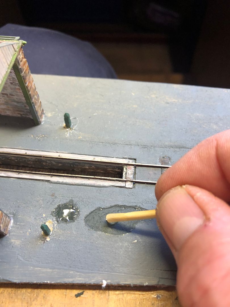
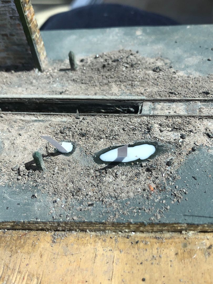
    I don’t think I have ever seen model puddles that were totally convincing, perhaps due to a varnish meniscus, non shiny surface to the water or maybe they’re just in the wrong place. So I put my thinking cap on: in fact this little project is helping me to practice some quite useful techniques. To represent the puddle I first of all gouged out a depression from the card surface and painted it dark gray.


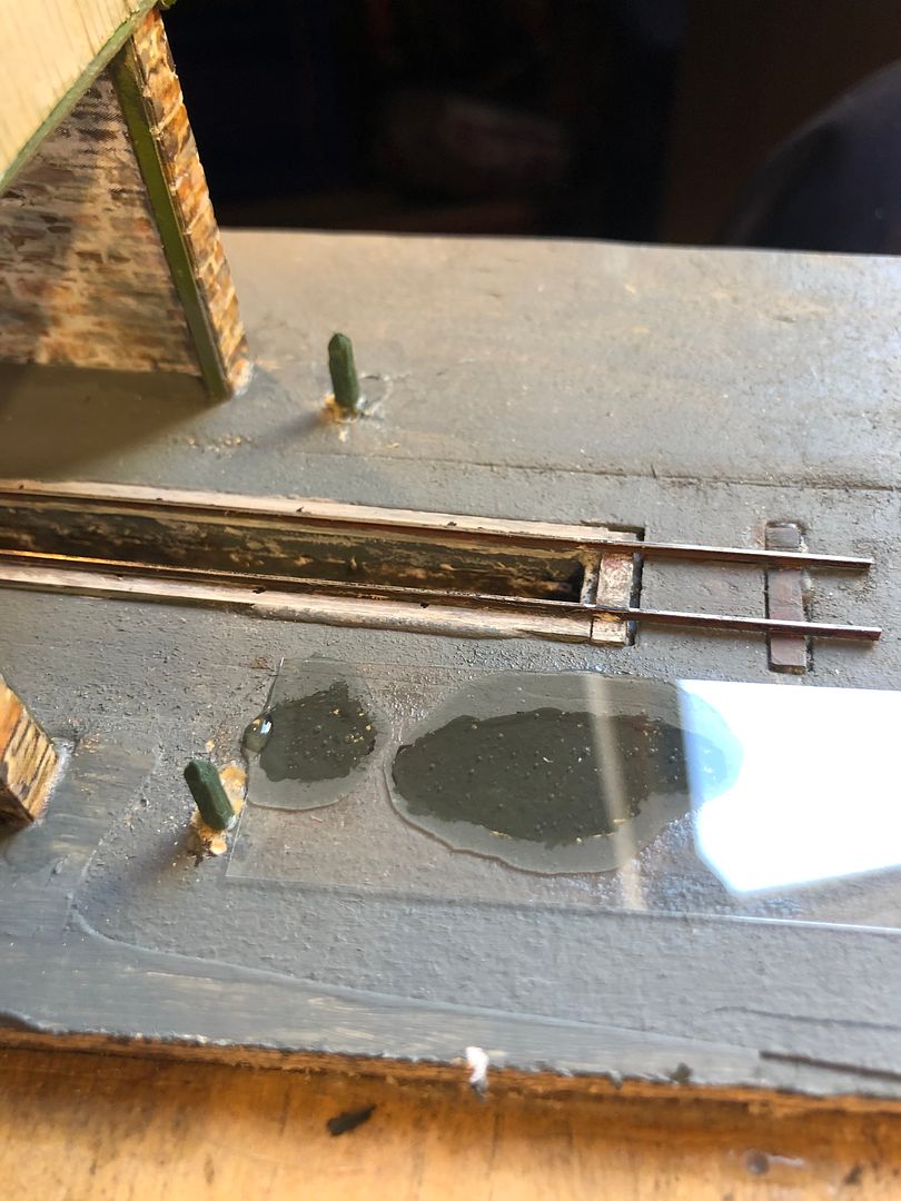
    This was then filled with epoxy resin (Araldite Precision) to an excess, taking care to mix the resin without air bubbles and to let it stand under a lamp for a short while to become nice and runny.


    The top of the water was then represented by a microscope slide cover slip which is 170um thick, gently laid down on the resin, with just a little pressure to squeeze out any excess.


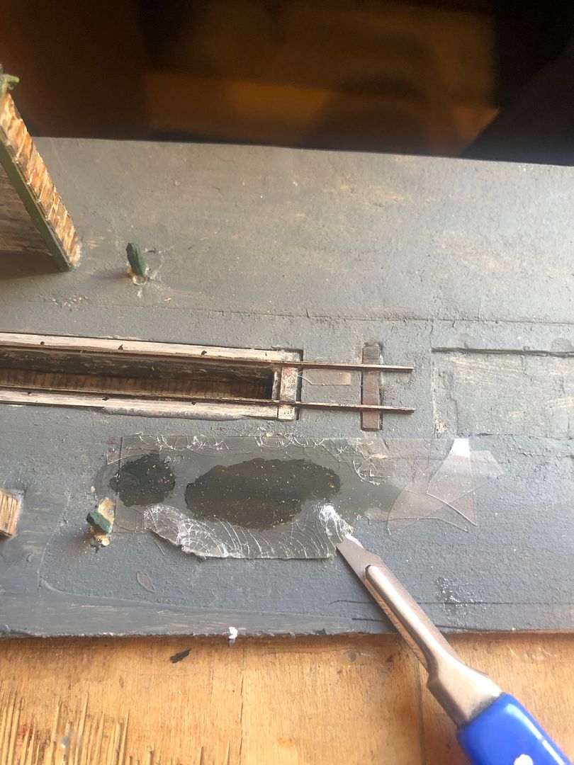
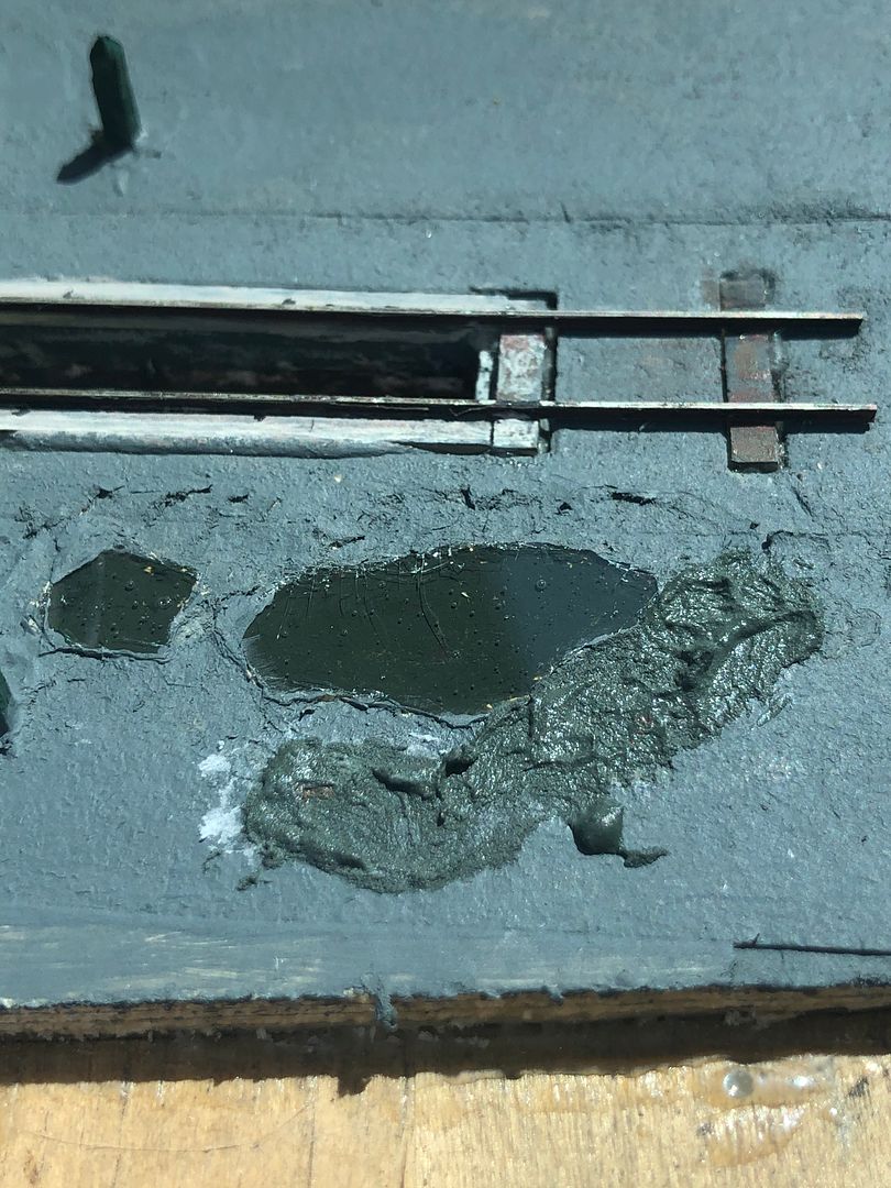
    Once the resin had cured, the coverslip was broken away with the edge of a scalpel. Somewhat annoyingly, this actually took some of the surrounding earth away as well, whilst the cover glass remained stuck to the main puddle.


    The ground was therefore made good with a coloured plaster slurry to just above the top of the coverslip.


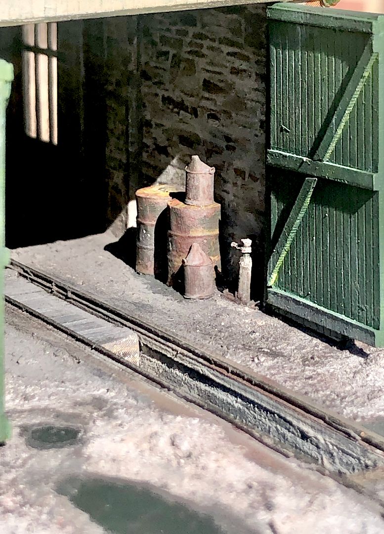
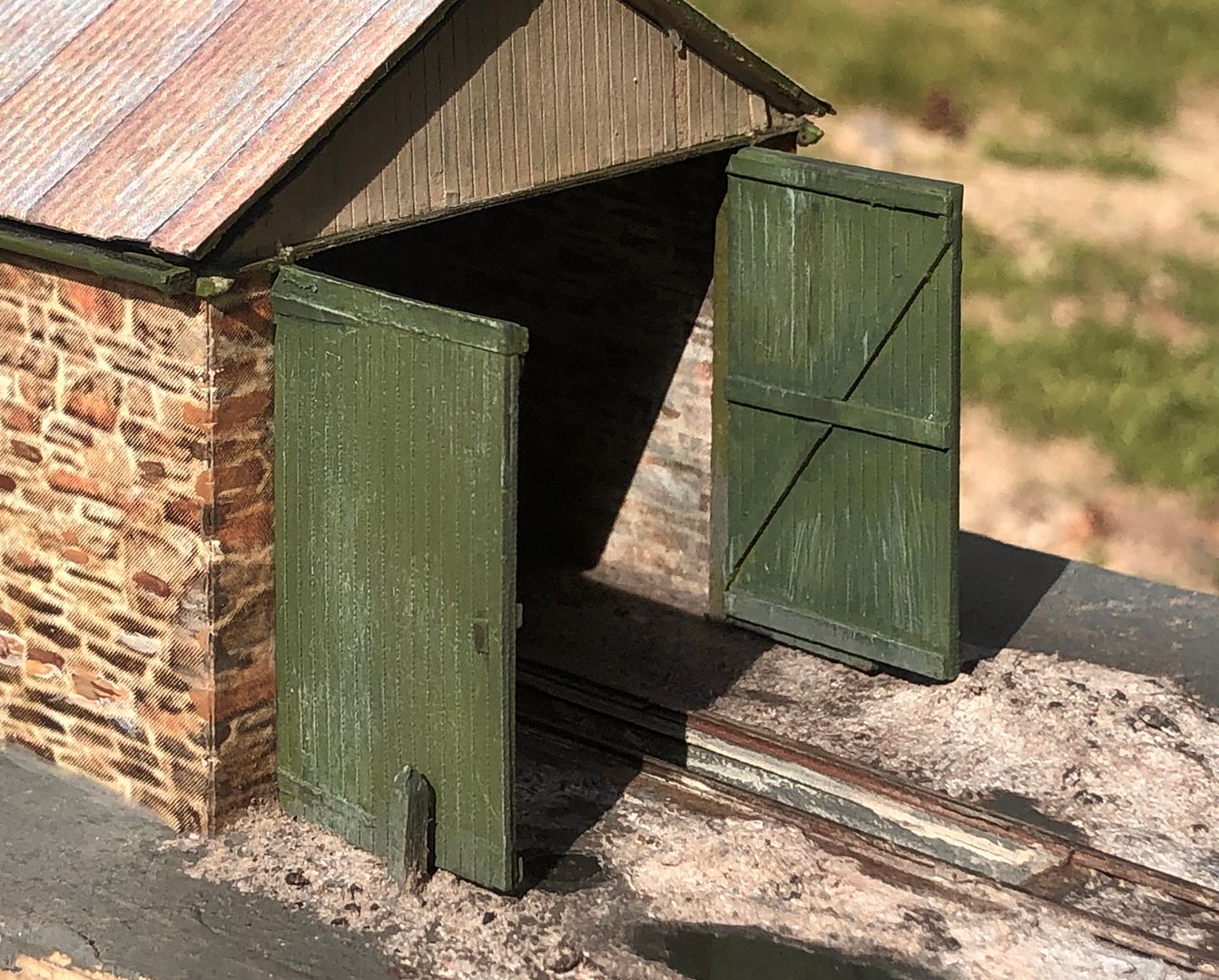
    Now obviously a loco shed area would be covered in ash and this was represented by ground up ash from my miniature traction engine.
    Whilst ash powder can be held in place by a layer of PVA glue to some extent, a more natural effect can be produced by using sprayed matt varnish to help lock the loose ash together. This would also represent the surface where the puddle has started to dry out. However, I didn’t want matt water over the whole puddle, so this was covered with PVA glue, incorporating a strip of paper to remove it more easily after the spraying.


    The end result gives a glass-like reflection from the water - funny that - and avoids problems of menisci and an irregular surface. The building itself needs further work around the roof (just resting in place in these images) and more details.


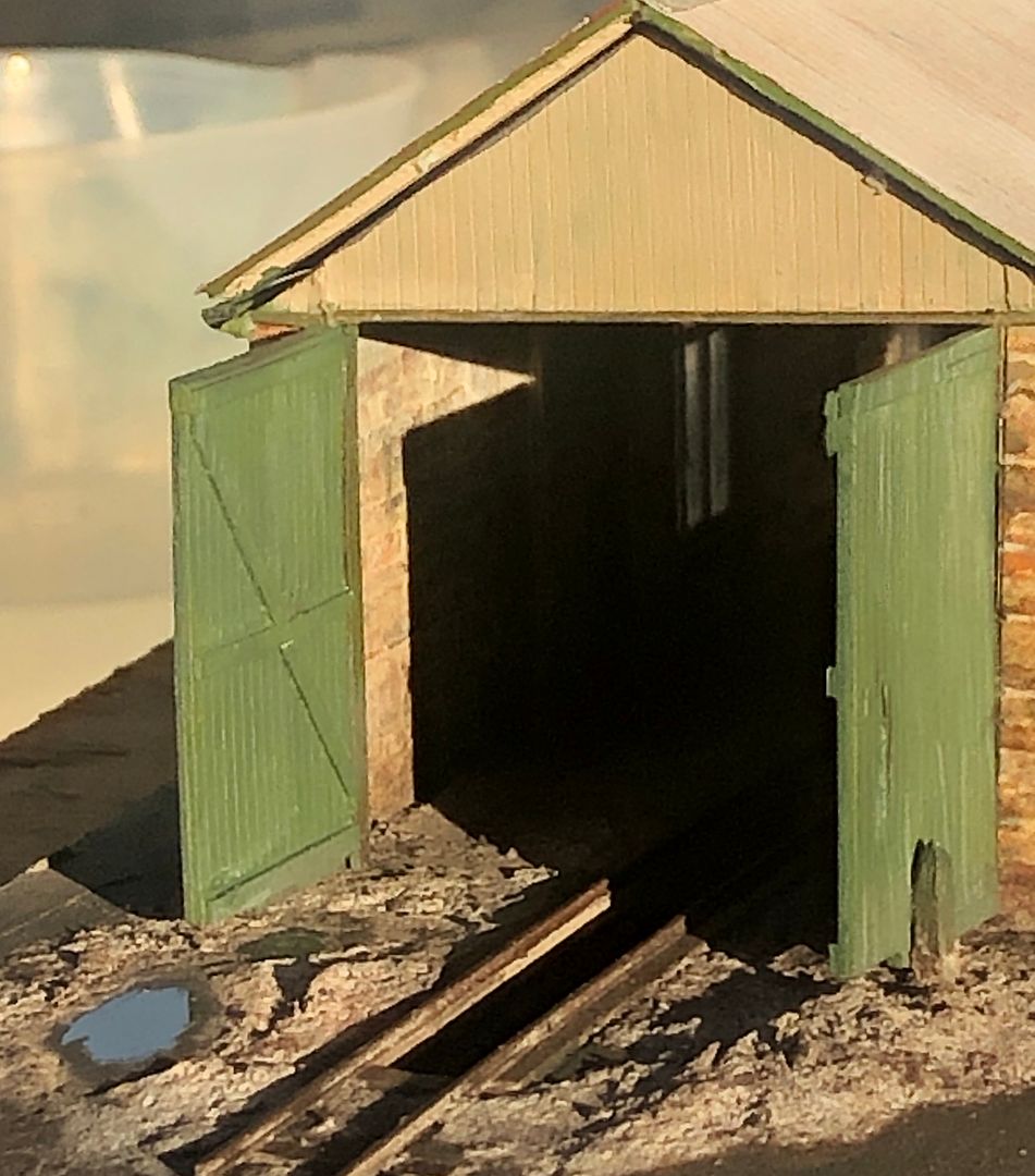
    Quite a lot of work for two little puddles, do you think it was worth it?


    Tim
     
    Sign of the times
  • Tim Watson

    Western Thunderer
    I have made good progress today on the enamel signs on the engine shed. I have trawled the internet for near equivalent images of prototype enamel signs to those shown in the L&B bible, Measured & Drawn, as well as any photos of the station that I have on file. These images were then captured as a photo with a screen shot and then cropped to the border, with other image distortions corrected using the iPad photo manipulation software: it is remarkably powerful, with clever adjustments for distortions inherent with a phone camera lens. This image shows one of the rather poorer specimens.


    In fact quite a lot of the prototype signs showed major damage and rusting and so they were cleaned up and touched up after importing the photos into NotePad Pro, a drawing package, again on the iPad: looks pretty crude at this magnification!


    These rectified images were again re-saved into ‘Photos’ to then be imported into a slide in PowerPoint on my laptop. Photos can easily be manipulated for exact size in PowerPoint and borders of the correct colour re-instated, where these were cropped. The slide was made up of all the enamel signs I could find for Lynton and one extra for self promotion: this was finally saved as a PDF that can be printed off on an A4 sheet at correct size for 4mm scale.


    The signs were run off at high resolution on matt photo quality paper on my inkjet printer. I am not convinced that signs should be glossy in this scale: the photographic effect of the enamel is sufficient. The sheet was given a light spray with Tamiya light grey undercoat to seal it on the back and the edges touched in with a felt tip pen once the signs were cut out.


    The signs in use at Lynton varied over time and they certainly give a lovely splash of colour to an otherwise quite lacklustre building. The image manipulation is pretty basic stuff, but you have the advantage that all the errors reduce as the items get printed to scale size.

    Tim
     
    Engineering
  • Tim Watson

    Western Thunderer
    I have made a start on the axles and wheel sets for Yeo, the first engine for Lynton. The standards are based on those of the 2mm Scale Association, but minus 1.42mm.

    The Heljan wheels are actually very fine as made, but to work in the narrower FS flange-ways require a thinner flange. The wheels were thinned mainly on the rear and a little bit off the front face, being held in a step collet. There is no need to modify the tread diameter, so maintaining concentricity.


    The new 2mm axles were turned from watchmakers pivot steel: it is very hard and has a highly polished surface. A 1.5mm diameter by 1mm deep shoulder was turned on the end using a TC tool.


    The fly crank webs will be made next using 1mm thick steel, fitted up against the shouldered axle. What will become apparent, when the valve gear is complete, is that the engine won’t look as if its got it’s elbows sticking out, compared to the commercial model.

    Tim
     
    Last edited:
    The Joys of valve gear
  • Tim Watson

    Western Thunderer
    Making this work will be a challenge.


    Photos by Owen Chapman

    It would be useful to have some dimensions for the valve gear, as these are going to be very critical. I spent most of today working out chassis dimensions and roughing out the frames.

    Tim
     
    Last edited:
    The mating game...
  • Tim Watson

    Western Thunderer
    I started to mate the new chassis to the body substructure of the Heljan loco this evening. The design of this engine is really quite complex and it took a lot of head scratching to work out how to reverse engineer a new chassis into it.

    AACD889C-FD1C-4517-9335-98497AC01BE4.jpeg.efe12fa37ebe054cf7095eb3c1b73724.jpeg


    The back end of the plastic frames were cut off and the cast fixing narrowed so that it fitted between the brass frames, with the plastic rearward extension on the outside.
    1BD10FF1-42C0-4142-B3B4-B3D89A3109E4.jpeg.1da76a9c73e1f9bb706429281047b0e2.jpeg


    The cast internal engine weights have been on the milling machine having space made internally.
    AA72AC47-B921-4A59-88A3-F87EA3A49E5D.jpeg.f7fe39023d7267c64bad3ac4af4fedfa.jpeg


    This little gadget is very useful for measuring casting thicknesses DENTAL WAX TYPE IWANSON CROWN CALIPER TENTH DIAMOND GAUGE ORTHODONTIC MEASURING 7437328019040 | eBay
    BF58F5C3-1D6A-4AC7-989F-76AC47401FAE.jpeg.d2de04435d95d2ba27eead23bc9c8f72.jpeg


    The roughly put-together castings gives a clue as to why there is need for a bit more internal space.


    Tim
     
    Back to the future
  • Tim Watson

    Western Thunderer
    With the outside cranks and the somewhat complicated valve gear I thought it would be advisable to be able to drop the wheel sets. To that end, the frames were dismantled and slots milled downwards. The small vertical holes in the frames had been drilled already to take 16BA fixing bolts.


    The bottom half of the bearing and keeper was milled from two pieces of 1.5mm thick brass sweated together, with corresponding holes drilled for the fixing bolts. As ever, working on both together saves a lot of time and is easier to file true.


    After adjustments the keepers can be seen trial fitted, but before the bearings were properly adjusted.


    The Heljan model has no representation of the brake gear and so the keeper was always intended to represent these. However, in reality the rods are set back behind the frames. To achieve this effect, a rebate was milled down the outer and lower edges of each side of the keep.


    The bulk of the keep was then filed away close to the frames, but keeping representations of the brake hangers and, of course the bottom halves of the bearings. It’s just roughly placed in this photo and will require further refinement and fitting for the axles.


    Quite a heavy evening’s work - the last time I made a chassis like this was for the Baldwin 2-6-0, started back in 1982! Soon be time to get the chassis and wheels all assembled.

    Tim
     
    Last edited:
    Top